engine mount ISUZU KB P190 2007 Workshop Manual PDF
[x] Cancel search | Manufacturer: ISUZU, Model Year: 2007, Model line: KB P190, Model: ISUZU KB P190 2007Pages: 6020, PDF Size: 70.23 MB
Page 1340 of 6020
EXHAUST SYSTEM 6F – 7
GENERAL DESCRIPTION
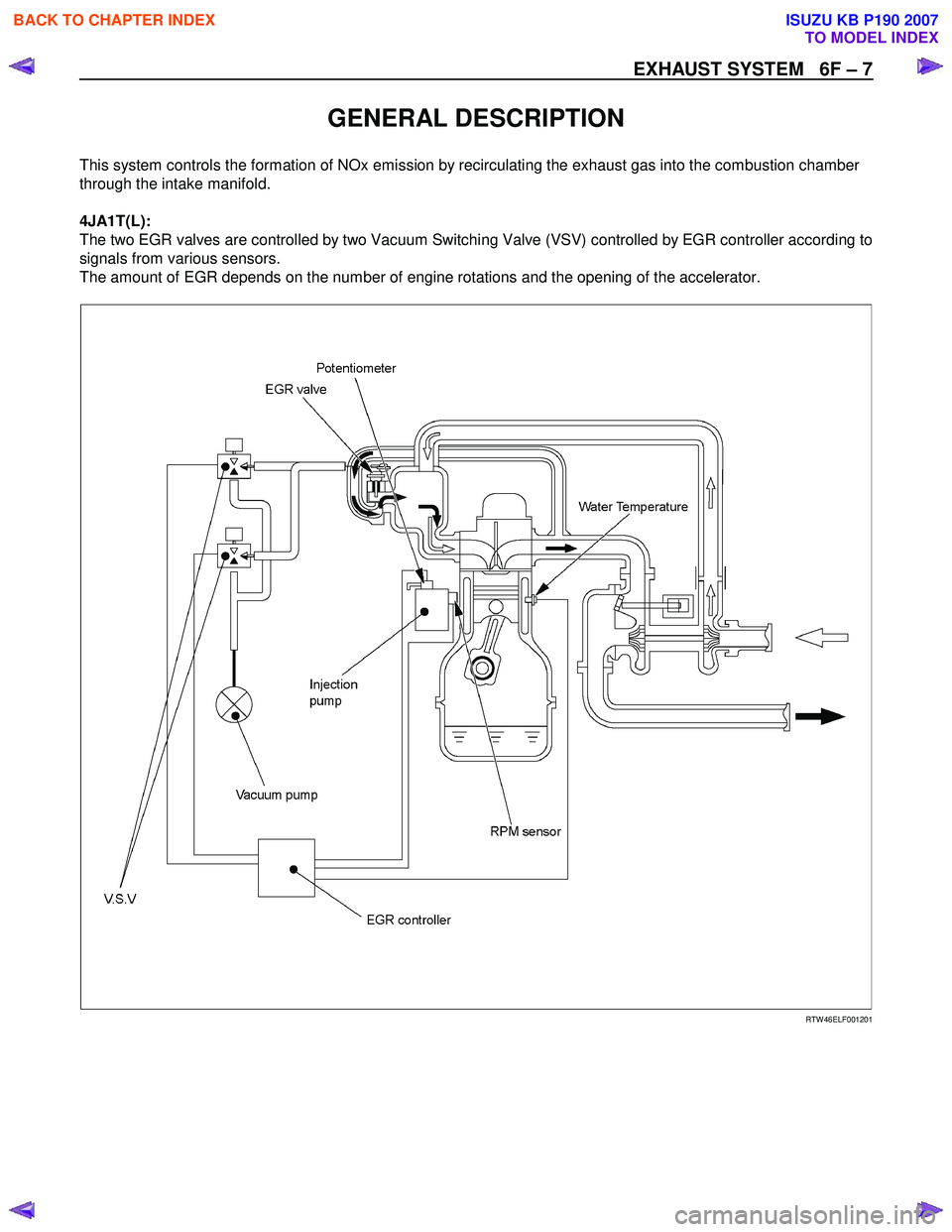
This system controls the formation of NOx emission by recirculating the exhaust gas into the combustion chamber
through the intake manifold.
4JA1T(L):
The two EGR valves are controlled by two Vacuum Switching Valve (VSV) controlled by EGR controller according to
signals from various sensors.
The amount of EGR depends on the number of engine rotations and the opening of the accelerator.
RTW 46ELF001201
BACK TO CHAPTER INDEX
TO MODEL INDEX
ISUZU KB P190 2007
Page 1361 of 6020
ENGINE MECHANICAL (4JK1/4JJ1) 6A-1
SECTION 6A
ENGINE MECHANICAL (4JK1/4JJ1)
TABLE OF CONTENTS
ISUZU DIESEL ENGINE (4JK1/4JJ1) ................ 6A-3
Service Precautions ........................................ 6A-3
Trouble Shooting ............................................. 6A-8
Main Data and Specifications .......................... 6A-13
Special Tools ................................................... 6A-14
Engine Assembly................................................ 6A-15 Removal .......................................................... 6A-15
Installation ....................................................... 6A-17
Special Tools ................................................... 6A-19
Engine Mount ..................................................... 6A-20 Components .................................................... 6A-20
Removal .......................................................... 6A-21
Installation ....................................................... 6A-21
Torque Specifications...................................... 6A-22
Special Tools ................................................... 6A-22
Cylinder Head Cover .......................................... 6A-23 Components .................................................... 6A-23
Removal .......................................................... 6A-24
Installation ....................................................... 6A-25
Intake Manifold ................................................... 6A-27 Components (Standard Output) ...................... 6A-27
Components (High Output) ............................. 6A-28
Removal .......................................................... 6A-29
Installation ....................................................... 6A-31
Torque Specifications...................................... 6A-32
Turbocharger and Exhaust Manifold (Standard Output) ........................................... 6A-33
Components .................................................... 6A-33
Removal .......................................................... 6A-34
Inspection ........................................................ 6A-36
Installation ....................................................... 6A-37
Torque Specifications...................................... 6A-40
Turbocharger (High Output) ............................... 6A-41 Components .................................................... 6A-41
Removal .......................................................... 6A-42
Inspection ........................................................ 6A-43
Installation ....................................................... 6A-44
Torque Specifications...................................... 6A-45
Exhaust Manifold (High Output) ......................... 6A-46 Components .................................................... 6A-46
Removal .......................................................... 6A-47
Inspection ........................................................ 6A-47
Installation ....................................................... 6A-47
Torque Specifications...................................... 6A-49
Timing Gear Train .............................................. 6A-50 Components .................................................... 6A-50
Removal .......................................................... 6A-51
Disassembly .................................................... 6A-53
Reassembly .................................................... 6A-53
Inspection ........................................................ 6A-54
Installation ....................................................... 6A-55
Torque Specifications...................................... 6A-58
Camshaft Assembly ........................................... 6A-59 Components .................................................... 6A-59
Removal .......................................................... 6A-60
Disassembly .................................................... 6A-61
Reassembly .................................................... 6A-63
Installation ....................................................... 6A-64
Torque Specifications...................................... 6A-66
Special Tools................................................... 6A-66
Valve Stem Seal and Valve Spring .................... 6A-67 Components .................................................... 6A-67
Removal .......................................................... 6A-68
Inspection ........................................................ 6A-69
Installation ....................................................... 6A-70
Special Tools................................................... 6A-71
Cylinder Head..................................................... 6A-72 Components .................................................... 6A-72
Removal .......................................................... 6A-72
Disassembly .................................................... 6A-81
Inspection ........................................................ 6A-83
Reassembly .................................................... 6A-87
Installation ....................................................... 6A-89
Torque Specifications...................................... 6A-100
Special Tools................................................... 6A-100
Piston and Connecting Rod................................ 6A-101 Components .................................................... 6A-101
Removal .......................................................... 6A-101
Disassembly .................................................... 6A-102
Reassembly .................................................... 6A-107
Installation ....................................................... 6A-108
Torque Specifications...................................... 6A-110
BACK TO CHAPTER INDEX
TO MODEL INDEX
ISUZU KB P190 2007
Page 1377 of 6020
ENGINE MECHANICAL (4JK1/4JJ1) 6A-17
RTW 56ASH004401
Legend
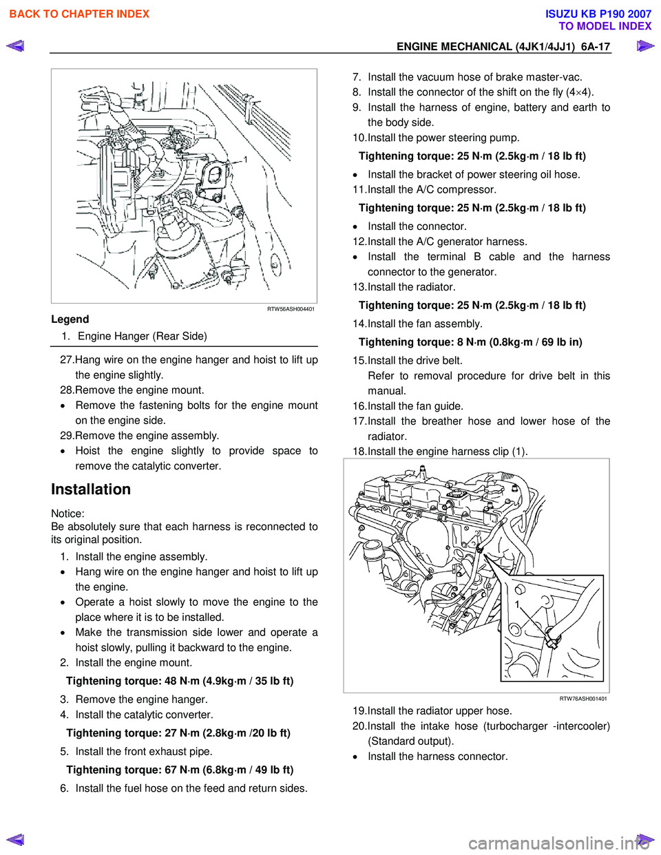
1. Engine Hanger (Rear Side)
27.Hang wire on the engine hanger and hoist to lift up
the engine slightly.
28.Remove the engine mount.
• Remove the fastening bolts for the engine mount
on the engine side.
29.Remove the engine assembly.
• Hoist the engine slightly to provide space to
remove the catalytic converter.
Installation
Notice:
Be absolutely sure that each harness is reconnected to
its original position.
1. Install the engine assembly.
• Hang wire on the engine hanger and hoist to lift up
the engine.
• Operate a hoist slowly to move the engine to the
place where it is to be installed.
• Make the transmission side lower and operate a
hoist slowly, pulling it backward to the engine.
2. Install the engine mount.
Tightening torque: 48 N ⋅
⋅⋅
⋅
m (4.9kg ⋅
⋅⋅
⋅
m / 35 lb ft)
3. Remove the engine hanger.
4. Install the catalytic converter.
Tightening torque: 27 N ⋅
⋅⋅
⋅
m (2.8kg ⋅
⋅⋅
⋅
m /20 lb ft)
5. Install the front exhaust pipe. Tightening torque: 67 N ⋅
⋅⋅
⋅
m (6.8kg ⋅
⋅⋅
⋅
m / 49 lb ft)
6. Install the fuel hose on the feed and return sides.
7. Install the vacuum hose of brake master-vac.
8. Install the connector of the shift on the fly (4 ×4).
9. Install the harness of engine, battery and earth to the body side.
10.Install the power steering pump.
Tightening torque: 25 N ⋅
⋅⋅
⋅
m (2.5kg ⋅
⋅⋅
⋅
m / 18 lb ft)
• Install the bracket of power steering oil hose.
11.Install the A/C compressor.
Tightening torque: 25 N ⋅
⋅⋅
⋅
m (2.5kg ⋅
⋅⋅
⋅
m / 18 lb ft)
• Install the connector.
12.Install the A/C generator harness.
• Install the terminal B cable and the harness
connector to the generator.
13.Install the radiator.
Tightening torque: 25 N ⋅
⋅⋅
⋅
m (2.5kg ⋅
⋅⋅
⋅
m / 18 lb ft)
14.Install the fan assembly. Tightening torque: 8 N ⋅
⋅⋅
⋅
m (0.8kg ⋅
⋅⋅
⋅
m / 69 lb in)
15.Install the drive belt.
Refer to removal procedure for drive belt in this manual.
16.Install the fan guide.
17.Install the breather hose and lower hose of the radiator.
18.Install the engine harness clip (1).
RTW 76ASH001401
19.Install the radiator upper hose.
20.Install the intake hose (turbocharger -intercooler) (Standard output).
• Install the harness connector.
BACK TO CHAPTER INDEX
TO MODEL INDEX
ISUZU KB P190 2007
Page 1380 of 6020
6A-20 ENGINE MECHANICAL (4JK1/4JJ1)
Engine Mount
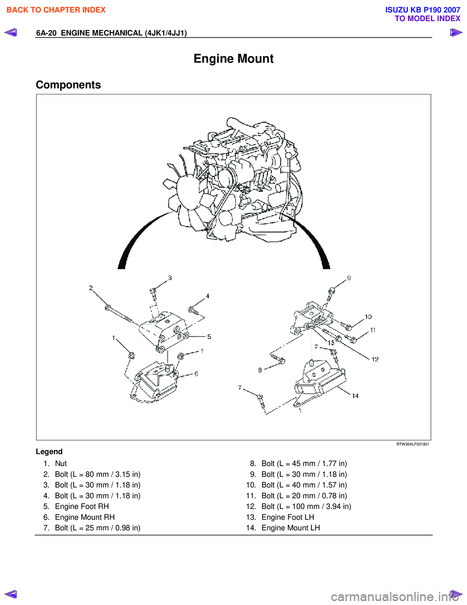
Components
RTW 56ALF001801
Legend 1. Nut
2. Bolt (L = 80 mm / 3.15 in)
3. Bolt (L = 30 mm / 1.18 in)
4. Bolt (L = 30 mm / 1.18 in)
5. Engine Foot RH
6. Engine Mount RH
7. Bolt (L = 25 mm / 0.98 in) 8. Bolt (L = 45 mm / 1.77 in)
9. Bolt (L = 30 mm / 1.18 in)
10. Bolt (L = 40 mm / 1.57 in)
11. Bolt (L = 20 mm / 0.78 in)
12. Bolt (L = 100 mm / 3.94 in)
13. Engine Foot LH
14. Engine Mount LH
BACK TO CHAPTER INDEX
TO MODEL INDEX
ISUZU KB P190 2007
Page 1381 of 6020

ENGINE MECHANICAL (4JK1/4JJ1) 6A-21
Removal
1. Remove the engine hood.
2. Remove the engine cover.
3. Set the hoist and the engine hanger of the special tool (special tool 5-8840-2823-0).
4. Remove the engine mount.
• Before removing the engine mount, hang the engine with a hoist.
• Remove the bolts of the engine mount.
• Hoist the engine assembly slightly to remove the engine mount.
RTW 56ASH004501
Installation
1. Install the engine mount and tighten up with the
specified torque.
Tightening torque: 52 N ⋅
⋅⋅
⋅
m (5.3 kg ⋅
⋅⋅
⋅
m / 38 lb ft)
2. Install the engine cover.
3. Install the engine hood. • Check if nothing is wrong with the engine
mount by starting the engine.
BACK TO CHAPTER INDEX
TO MODEL INDEX
ISUZU KB P190 2007
Page 1383 of 6020
ENGINE MECHANICAL (4JK1/4JJ1) 6A-23
Cylinder Head Cover
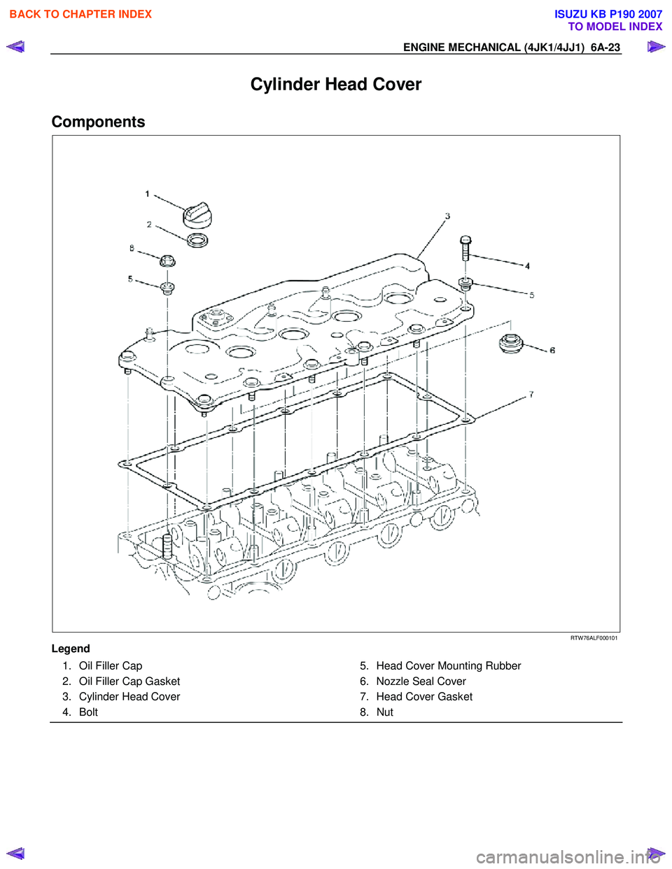
Components
RTW 76ALF000101
Legend 1. Oil Filler Cap
2. Oil Filler Cap Gasket
3. Cylinder Head Cover
4. Bolt 5. Head Cover Mounting Rubber
6. Nozzle Seal Cover
7. Head Cover Gasket
8. Nut
BACK TO CHAPTER INDEX
TO MODEL INDEX
ISUZU KB P190 2007
Page 1385 of 6020
ENGINE MECHANICAL (4JK1/4JJ1) 6A-25
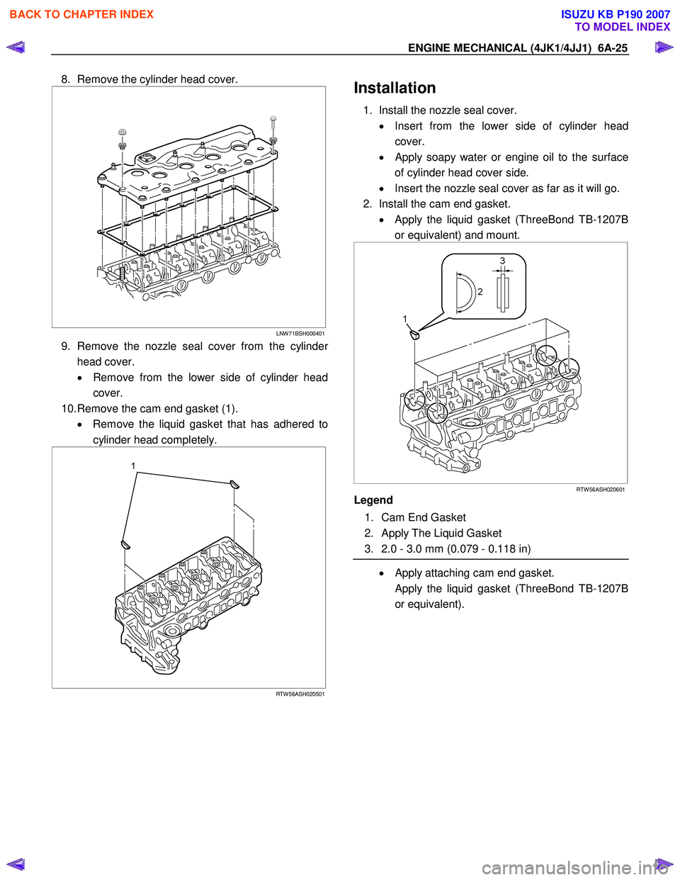
8. Remove the cylinder head cover.
LNW 71BSH000401
9. Remove the nozzle seal cover from the cylinder
head cover.
• Remove from the lower side of cylinder head
cover.
10. Remove the cam end gasket (1). • Remove the liquid gasket that has adhered to
cylinder head completely.
RTW 56ASH020501
Installation
1. Install the nozzle seal cover.
• Insert from the lower side of cylinder head
cover.
•
Apply soapy water or engine oil to the surface
of cylinder head cover side.
• Insert the nozzle seal cover as far as it will go.
2. Install the cam end gasket. • Apply the liquid gasket (ThreeBond TB-1207B
or equivalent) and mount.
RTW 56ASH020601
Legend
1. Cam End Gasket
2. Apply The Liquid Gasket
3. 2.0 - 3.0 mm (0.079 - 0.118 in)
• Apply attaching cam end gasket.
Apply the liquid gasket (ThreeBond TB-1207B or equivalent).
BACK TO CHAPTER INDEX
TO MODEL INDEX
ISUZU KB P190 2007
Page 1449 of 6020
ENGINE MECHANICAL (4JK1/4JJ1) 6A-89
Installation
1. Select the cylinder head gasket.
Cylinder Head Gasket Selection
Cylinder head gasket is determined by the piston head
projection from the cylinder body upper surface, in orde
r
to improve engine performance.
Three types of gasket are provided with difference o
f
thickness. Select the appropriate one out of three
grades of
gasket, according to the following procedure.
Before measurement, clear off carbon from the piston
head and cylinder body surface and also clean the
place where the gasket was installed.
011LX011
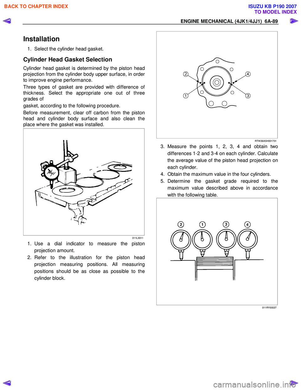
1. Use a dial indicator to measure the piston
projection amount.
2. Refer to the illustration for the piston head projection measuring positions. All measuring
positions should be as close as possible to the
cylinder block.
RTW 36ASH001701
3. Measure the points 1, 2, 3, 4 and obtain two
differences 1-2 and 3-4 on each cylinder. Calculate
the average value of the piston head projection on
each cylinder.
4. Obtain the maximum value in the four cylinders.
5. Determine the gasket grade required to the maximum value described above in accordance
with the following table.
011RY00027
BACK TO CHAPTER INDEX
TO MODEL INDEX
ISUZU KB P190 2007
Page 1461 of 6020
ENGINE MECHANICAL (4JK1/4JJ1) 6A-101
Piston and Connecting Rod
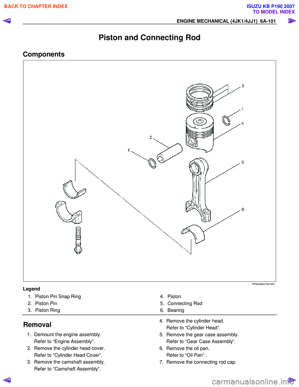
Components
RTW A56ALF001601
Legend 1. Piston Pin Snap Ring
2. Piston Pin
3. Piston Ring 4. Piston
5. Connecting Rod
6. Bearing
Removal
1. Demount the engine assembly.
Refer to “Engine Assembly”.
2. Remove the cylinder head cover.
Refer to “Cylinder Head Cover”.
3. Remove the camshaft assembly.
Refer to “Camshaft Assembly”.
4. Remove the cylinder head.
Refer to “Cylinder Head”.
5. Remove the gear case assembly.
Refer to “Gear Case Assembly”.
6. Remove the oil pan.
Refer to “Oil Pan” .
7. Remove the connecting rod cap.
BACK TO CHAPTER INDEX
TO MODEL INDEX
ISUZU KB P190 2007
Page 1480 of 6020
6A-120 ENGINE MECHANICAL (4JK1/4JJ1)
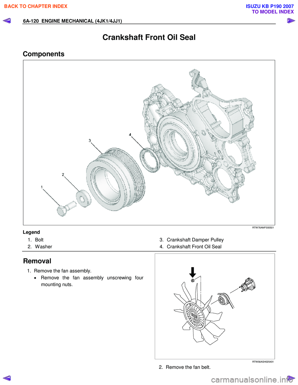
Crankshaft Front Oil Seal
Components
RTW 76AMF000501
Legend 1. Bolt
2. W asher 3. Crankshaft Damper Pulley
4. Crankshaft Front Oil Seal
Removal
1. Remove the fan assembly.
• Remove the fan assembly unscrewing fou
r
mounting nuts.
RTW 56ASH025401
2. Remove the fan belt.
BACK TO CHAPTER INDEX
TO MODEL INDEX
ISUZU KB P190 2007