ECO mode ISUZU KB P190 2007 Workshop Repair Manual
[x] Cancel search | Manufacturer: ISUZU, Model Year: 2007, Model line: KB P190, Model: ISUZU KB P190 2007Pages: 6020, PDF Size: 70.23 MB
Page 2641 of 6020
Engine Mechanical – V6 Page 6A1–162
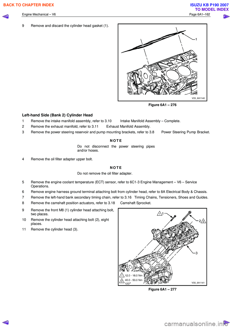
9 Remove and discard the cylinder head gasket (1).
Figure 6A1 – 276
Left-hand Side (Bank 2) Cylinder Head
1 Remove the intake manifold assembly, refer to 3.10 Intake Manifold Assembly – Complete.
2 Remove the exhaust manifold, refer to 3.11 Exhaust Manifold Assembly.
3 Remove the power steering reservoir and pump mounting brackets, refer to 3.8 Power Steering Pump Bracket.
NOTE
Do not disconnect the power steering pipes
and/or hoses.
4 Remove the oil filter adapter upper bolt. NOTE
Do not remove the oil filter adapter.
5 Remove the engine coolant temperature (ECT) sensor, refer to 6C1-3 Engine Management – V6 – Service Operations.
6 Remove engine harness ground terminal attaching bolt from cylinder head, refer to 8A Electrical Body & Chassis.
7 Remove the left-hand bank secondary timing chain, refer to 3.16 Timing Chains, Tensioners, Shoes and Guides.
8 Remove the camshaft position actuators, refer to 3.18 Camshaft Sprocket.
9 Remove the front M8 (1) cylinder head attaching bolt, two places.
10 Remove the cylinder head attaching bolt (2), eight places.
11 Remove the cylinder head (3).
Figure 6A1 – 277
BACK TO CHAPTER INDEX
TO MODEL INDEX
ISUZU KB P190 2007
Page 2646 of 6020

Engine Mechanical – V6 Page 6A1–167
Inspect
Visual Inspection
1 Inspect the cylinder head (1) camshaft bearing
surfaces for the following conditions:
• excessive scoring or pitting,
• discoloration from overheating, and
• deformation from excessive wear.
2 If any of the above conditions exist on the camshaft bearing surfaces, replace the cylinder head. Do not
machine the camshaft bearing journals.
Figure 6A1 – 287
3 Inspect the cylinder head for the following: • Cracks, damage or pitting in the combustion chambers.
• Debris in the oil galleries. continue to clean the galleries until all debris is removed.
• Coolant leaks or damage to the deck face sealing surface. if coolant leaks are present, measure the surface
warpage as described under Cylinder Head Measurement within this Section.
• Burrs or any defects that would degrade the sealing of a new secondary camshaft chain tensioner gasket.
• Damage to any gasket surfaces.
• Damage to any threaded bolt holes.
• Burnt or eroded areas in the combustion chamber.
• Cracks in the exhaust ports and combustion chambers.
• External cracks in the water passages.
• Restrictions in the intake or exhaust passages.
• Restrictions in the cooling system passages.
• Rusted, damaged or leaking core plugs.
4 If the cylinder head is cracked or damaged, it must be replaced. No welding or patching of the cylinder head is recommended.
Cylinder Head Measurement
NOTE
For all cylinder head and associated component
specifications, refer to 5 Specifications.
Camshaft Journal Clearance
1 Install the camshaft bearing cap in the cylinder head without the camshaft.
2 Install the camshaft cap bolts and tighten to the correct torque specification
Camshaft bearing cap attaching bolt........8.0 – 12.0 Nm.
3 Measure the camshaft bearings using an inside micrometer.
4 Subtract the camshaft journal diameter from the camshaft bearing diameter. This will provide the running clearance. If the running clearance exceeds specifications and the camshaft journals are within specification, replace the
cylinder head.
Camshaft Journal Alignment
1 Ensure the camshafts are serviceable, refer to 3.19 Camshaft for measuring procedures.
BACK TO CHAPTER INDEX
TO MODEL INDEX
ISUZU KB P190 2007
Page 2649 of 6020
Engine Mechanical – V6 Page 6A1–170
Measurement Procedure
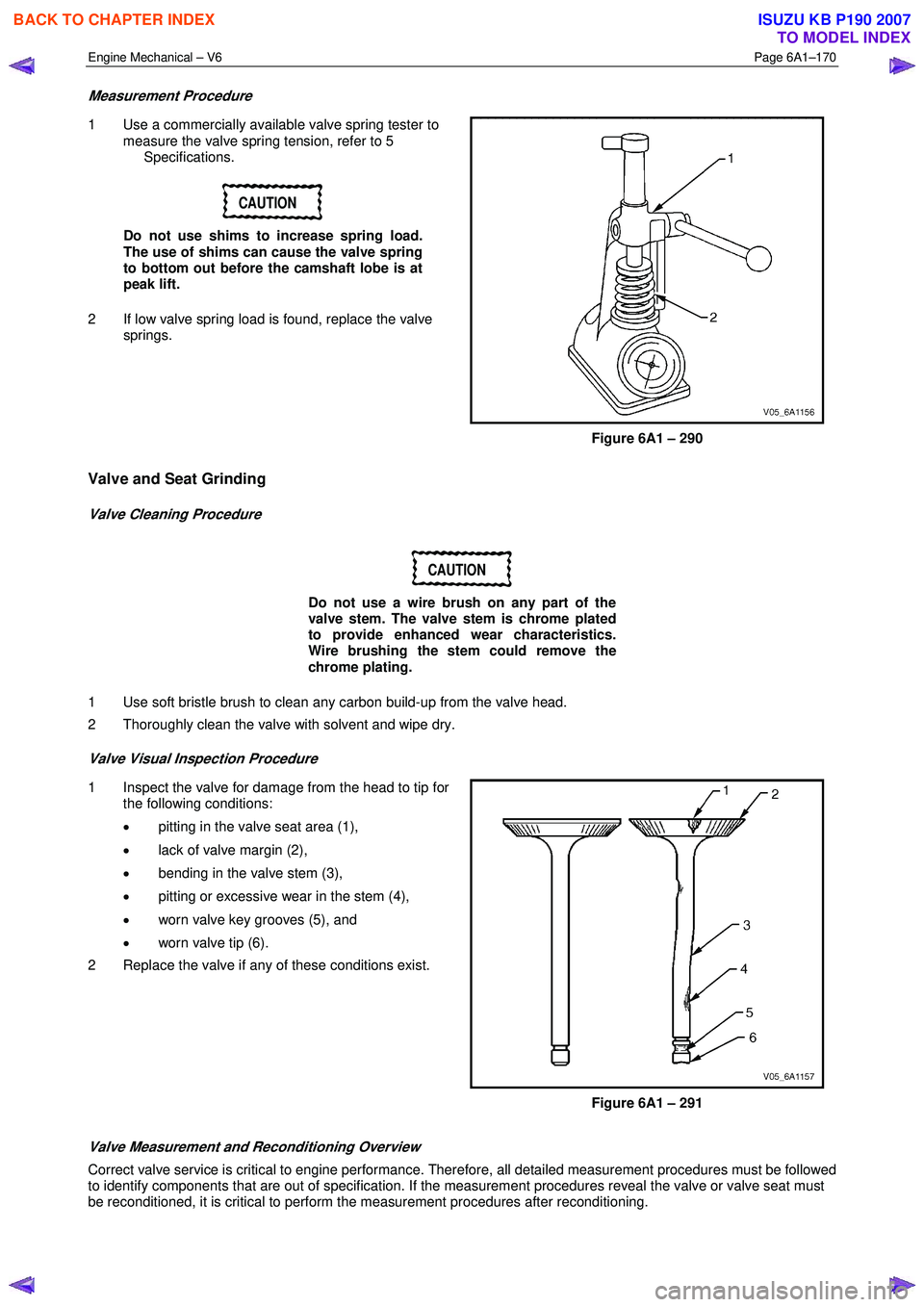
1 Use a commercially available valve spring tester to
measure the valve spring tension, refer to 5
Specifications.
CAUTION
Do not use shims to increase spring load.
The use of shims can cause the valve spring
to bottom out before the camshaft lobe is at
peak lift.
2 If low valve spring load is found, replace the valve springs.
Figure 6A1 – 290
Valve and Seat Grinding
Valve Cleaning Procedure
CAUTION
Do not use a wire brush on any part of the
valve stem. The valve stem is chrome plated
to provide enhanced wear characteristics.
Wire brushing the stem could remove the
chrome plating.
1 Use soft bristle brush to clean any carbon build-up from the valve head.
2 Thoroughly clean the valve with solvent and wipe dry.
Valve Visual Inspection Procedure
1 Inspect the valve for damage from the head to tip for the following conditions:
• pitting in the valve seat area (1),
• lack of valve margin (2),
• bending in the valve stem (3),
• pitting or excessive wear in the stem (4),
• worn valve key grooves (5), and
• worn valve tip (6).
2 Replace the valve if any of these conditions exist.
Figure 6A1 – 291
Valve Measurement and Reconditioning Overview
Correct valve service is critical to engine performance. Therefore, all detailed measurement procedures must be followed
to identify components that are out of specification. If the measurement procedures reveal the valve or valve seat must
be reconditioned, it is critical to perform the measurement procedures after reconditioning.
BACK TO CHAPTER INDEX
TO MODEL INDEX
ISUZU KB P190 2007
Page 2650 of 6020
Engine Mechanical – V6 Page 6A1–171
Valve Seat Width Measurement Procedure
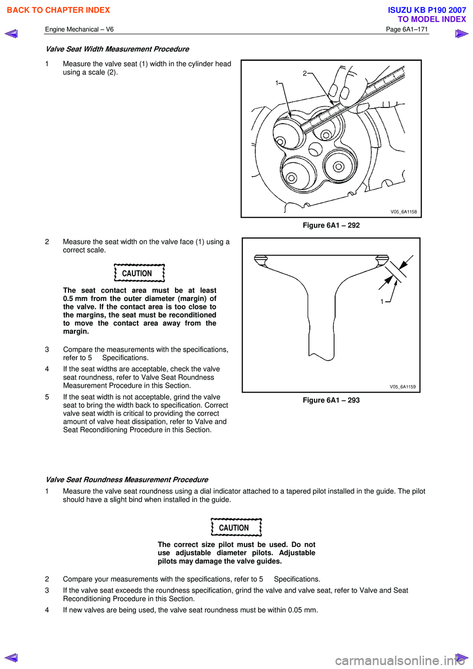
1 Measure the valve seat (1) width in the cylinder head
using a scale (2).
Figure 6A1 – 292
2 Measure the seat width on the valve face (1) using a correct scale.
CAUTION
The seat contact area must be at least
0.5 mm from the outer diameter (margin) of
the valve. If the contact area is too close to
the margins, the seat must be reconditioned
to move the contact area away from the
margin.
3 Compare the measurements with the specifications, refer to 5 Specifications.
4 If the seat widths are acceptable, check the valve seat roundness, refer to Valve Seat Roundness
Measurement Procedure in this Section.
5 If the seat width is not acceptable, grind the valve seat to bring the width back to specification. Correct
valve seat width is critical to providing the correct
amount of valve heat dissipation, refer to Valve and
Seat Reconditioning Procedure in this Section.
Figure 6A1 – 293
Valve Seat Roundness Measurement Procedure
1 Measure the valve seat roundness using a dial indicator attached to a tapered pilot installed in the guide. The pilot should have a slight bind when installed in the guide.
CAUTION
The correct size pilot must be used. Do not
use adjustable diameter pilots. Adjustable
pilots may damage the valve guides.
2 Compare your measurements with the specifications, refer to 5 Specifications.
3 If the valve seat exceeds the roundness specification, grind the valve and valve seat, refer to Valve and Seat Reconditioning Procedure in this Section.
4 If new valves are being used, the valve seat roundness must be within 0.05 mm.
BACK TO CHAPTER INDEX
TO MODEL INDEX
ISUZU KB P190 2007
Page 2651 of 6020
Engine Mechanical – V6 Page 6A1–172
Valve Margin Measurement Procedure
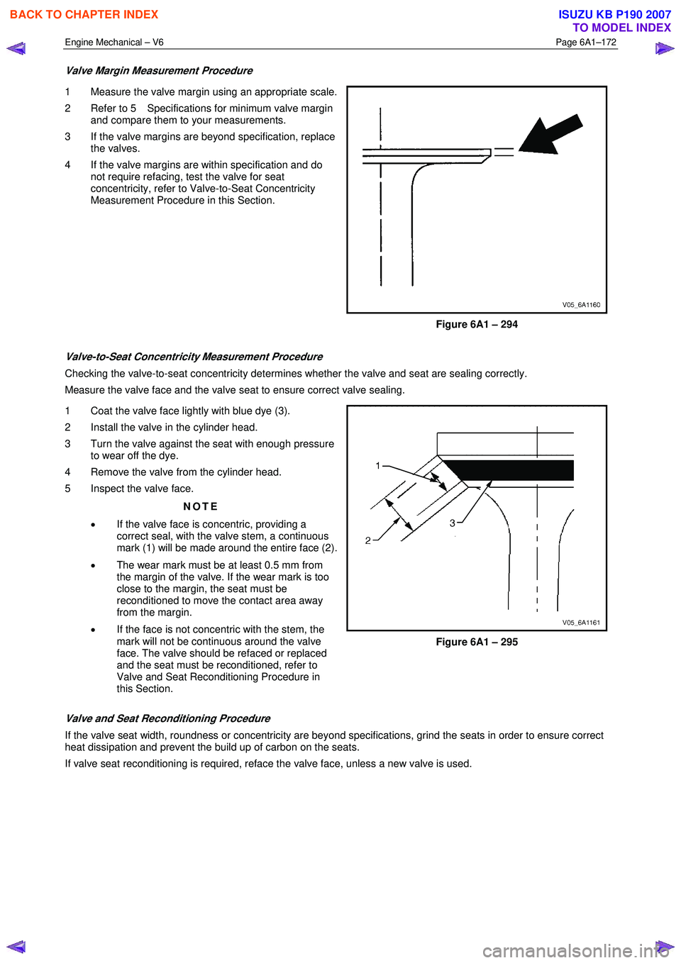
1 Measure the valve margin using an appropriate scale.
2 Refer to 5 Specifications for minimum valve margin and compare them to your measurements.
3 If the valve margins are beyond specification, replace the valves.
4 If the valve margins are within specification and do not require refacing, test the valve for seat
concentricity, refer to Valve-to-Seat Concentricity
Measurement Procedure in this Section.
Figure 6A1 – 294
Valve-to-Seat Concentricity Measurement Procedure
Checking the valve-to-seat concentricity determines whether the valve and seat are sealing correctly.
Measure the valve face and the valve seat to ensure correct valve sealing.
1 Coat the valve face lightly with blue dye (3).
2 Install the valve in the cylinder head.
3 Turn the valve against the seat with enough pressure to wear off the dye.
4 Remove the valve from the cylinder head.
5 Inspect the valve face.
NOTE
• If the valve face is concentric, providing a
correct seal, with the valve stem, a continuous
mark (1) will be made around the entire face (2).
• The wear mark must be at least 0.5 mm from
the margin of the valve. If the wear mark is too
close to the margin, the seat must be
reconditioned to move the contact area away
from the margin.
• If the face is not concentric with the stem, the
mark will not be continuous around the valve
face. The valve should be refaced or replaced
and the seat must be reconditioned, refer to
Valve and Seat Reconditioning Procedure in
this Section.
Figure 6A1 – 295
Valve and Seat Reconditioning Procedure
If the valve seat width, roundness or concentricity are beyond specifications, grind the seats in order to ensure correct
heat dissipation and prevent the build up of carbon on the seats.
If valve seat reconditioning is required, reface the valve face, unless a new valve is used.
BACK TO CHAPTER INDEX
TO MODEL INDEX
ISUZU KB P190 2007
Page 2663 of 6020
Engine Mechanical – V6 Page 6A1–184
4 Major Service Operations
ATTENTION
The V6 engine is a combination of numerous components, containing machined, honed, polished and lapped
surfaces manufactured on the latest, high technology production equipment. Many of the components
contain tolerances measured in thousandths of a millimetre. Consequently, when any engine component is to
be serviced, care and cleanliness are extremely important.
Prior to re-assembly of the V6 engine, all components must be cleaned and inspected in accordance with the
relevant procedures throughout this section, and replaced or repaired where required.
In addition to cleaning and inspecting components, a liberal coating of engine oil should be applied to friction
surfaces during assembly to protect and lubricate the surfaces on initial operation.
When performing any service operation contained in this Section, it should be understood that correct
cleaning and protection of machined surfaces and friction areas is part of the repair procedure. This is
considered standard workshop practice, even if not specifically stated. Torque values must be used as
specified during reassembly to ensure correct retention of all components.
Through out this section, fastener torque wrench specifications may be accompanied with the following
identification marks:
■ Fasteners must be replaced after loosening.
Fasteners either have micro encapsulated sealant applied or incorporate a mechanical thread lock and
should only be re-used once. If in doubt, replacement is recommended.
If one of these identification marks is present alongside a fastener torque wrench specification, the
recommendation regarding that fastener must be adhered to.
4.1 Engine Removal
CAUTION
• Allow the engine to cool to at least 50 °
°°
°
C,
before attempting fastener removal.
• As aluminium has a greater rate of thermal
expansion than that of cast iron,
aluminium bolt hole threads will change
dimension to a larger extent than cast iron
bolt threads.
• If a bolt or other threaded component is
removed before the engine is allowed to
cool to at least 50 °
°°
°
C, threads could be
pulled from the cylinder block or cylinder
head.
• Do not use impact tools to remove bolts
during engine disassembly. While this may
be common practice with cast iron engine
components, use of these tools is likely to
pull the aluminium threads in the cylinder
block or head of this engine.
BACK TO CHAPTER INDEX
TO MODEL INDEX
ISUZU KB P190 2007
Page 2677 of 6020
Engine Mechanical – V6 Page 6A1–198
k Timing chains, tensioners, shoes, guides & sprockets, refer to 3.16 Timing Chains, Tensioners, Shoes and
Guides.
l Cylinder head assemblies, refer to 3.22 Cylinder Head Assembly.
m Oil pan assembly, refer to 4.2 Oil Pan and Oil Pump Suction Pipe Assembly.
n Piston and connecting rod assemblies, refer to 4.5 Pistons, Pins, Rings, Connecting Rods and Big-end Bearings.
o Crankshaft assembly, refer to 4.6 Crankshaft and Main Bearings.
p Piston oil nozzles, refer 4.5 Pistons, Pins, Rings, Connecting Rods and Big-end Bearings.
Reassemble
Reassembly of the engine assembly is the reverse of the disassembly procedure.
Reinstall
Reinstallation of the engine assembly is the reverse to the removal procedure, noting the following:
NOTE
Refer to 6 Torque Wrench Specifications
for the correct torque specifications.
1 Tighten the fasteners to the correct torque specification.
Engine ground connector bolt
torque specification ............................................10.0 Nm
Power steering high pressure line
attaching bolt torque specification .............8.0 – 12.0 Nm
Power steering high pressure line
flare nut torque specification ...................25.0 – 35.0 Nm
Engine mount to frame attaching bolt
torque specification .................................44.0 – 60.0 Nm
Knock Sensor Attaching Nut
torque specification ............................................23.0 Nm
2 Use only the specified engine lubricant type and quantity. It is recommended that a fluorescent oil dye, such as that contained in J 28481-B, be added to assist in any future oil leak diagnosis.
3 Fill the cooling system with the correct quantity and grade of coolant, refer to 6B1 Engine Cooling – V6.
4 Check transmission fluid level, replenishing as required, using the specified lubricant for the transmission fitted, refer to 7C1 Automatic – 4L60E – General Information.
5 Disable the ignition system, refer to 6C1-3 Engine Management – V6 – Service Operations.
6 Crank the engine several times. Listen for any unusual noises or evidence that parts are binding.
7 Enable the ignition system. Start the engine and listen for any unusual noises.
8 Check the vehicle oil pressure gauge or warning indicator and confirm the engine has acceptable oil pressure. If required, install an oil pressure gauge and measure the engine oil pressure, refer to 2.19 Engine Oil Pressure
Diagnosis.
9 Run the engine at about 1,000 r.p.m. until the engine has reached normal operating temperature.
10 Listen for any unusual noises.
11 Check for oil, fuel, coolant and exhaust leaks while the engine is running, correcting as required.
12 Perform a final inspection for correct engine oil and coolant levels.
4.2 Oil Pan and Oil Pump Suction Pipe Assembly
Remove
1 Remove the engine assembly from the vehicle, refer to 4.1 Engine .
2 Separate the engine and transmission assemblies, refer to 7C1 Automatic – 4L60E – General Information.
3 Mount the engine assembly on a suitable engine stand.
4 Remove the engine front cover, refer to 3.15 Front Cover Assembly.
BACK TO CHAPTER INDEX
TO MODEL INDEX
ISUZU KB P190 2007
Page 2695 of 6020
Engine Mechanical – V6 Page 6A1–216
Connecting Rod Measurement Procedure
Piston Pin End
NOTE
Measurements of all components should be
taken with the components at normal room
temperature.
1 Using an outside micrometer (1), take two measurements of the piston pin (2) in the area of the
connecting rod contact.
Figure 6A1 – 392
2 Using an inside micrometer, measure the connecting rod piston pin bore (1).
3 Subtract the piston pin diameter from the piston pin bore.
4 Compare the clearance measurements listed in the specifications, refer to 5 Specifications.
5 If the clearance is excessive, replace the piston pin. If a new pin does not resolve the clearance problem,
replace the connecting rod.
Figure 6A1 – 393
Crankshaft Bearing End
NOTE
Measurements of all components should be
taken with the components at normal room
temperature.
1 Using an inside micrometer, measure the connecting rod crankshaft bearing bore (1).
2 Compare the bore measurements listed in the specifications, refer to 5 Specifications.
3 Replace the connecting rod if the bore is out of specification. Do not recondition the connecting rod.
Figure 6A1 – 394
BACK TO CHAPTER INDEX
TO MODEL INDEX
ISUZU KB P190 2007
Page 2697 of 6020
Engine Mechanical – V6 Page 6A1–218
Piston Ring
NOTE
The ends of the expander must be facing
toward the top of the piston.
1 Correctly orient the oil control ring expander (1) before installation.
Figure 6A1 – 397
2 Using a piston ring expander, install the oil control ring assembly using the following procedure:
3 Install the expander ring (3).
4 Install the two oil scraper rings (4). Expand the rings only enough to clear the piston diameter. Over-
expanding the piston rings will distort or crack the
rings.
5 Install the second (2) and top (1) piston rings as follows.
Figure 6A1 – 398
6 Using the ring expander (1), install the second piston ring (2) onto the piston (3). Do not over-expand the
ring. Repeat for the top ring.
Figure 6A1 – 399
BACK TO CHAPTER INDEX
TO MODEL INDEX
ISUZU KB P190 2007
Page 2698 of 6020
Engine Mechanical – V6 Page 6A1–219
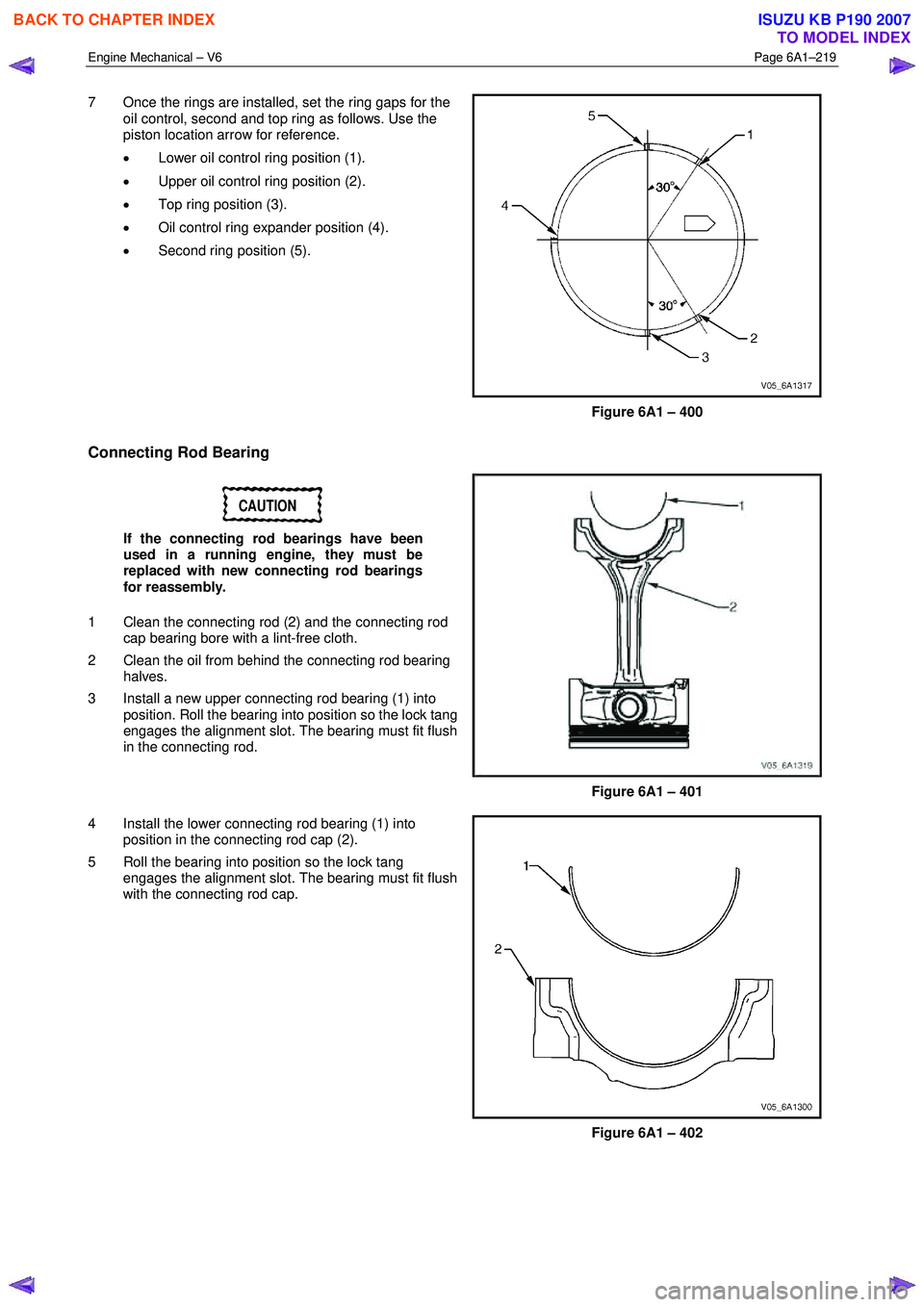
7 Once the rings are installed, set the ring gaps for the
oil control, second and top ring as follows. Use the
piston location arrow for reference.
• Lower oil control ring position (1).
• Upper oil control ring position (2).
• Top ring position (3).
• Oil control ring expander position (4).
• Second ring position (5).
Figure 6A1 – 400
Connecting Rod Bearing
CAUTION
If the connecting rod bearings have been
used in a running engine, they must be
replaced with new connecting rod bearings
for reassembly.
1 Clean the connecting rod (2) and the connecting rod cap bearing bore with a lint-free cloth.
2 Clean the oil from behind the connecting rod bearing halves.
3 Install a new upper connecting rod bearing (1) into position. Roll the bearing into position so the lock tang
engages the alignment slot. The bearing must fit flush
in the connecting rod.
Figure 6A1 – 401
4 Install the lower connecting rod bearing (1) into position in the connecting rod cap (2).
5 Roll the bearing into position so the lock tang engages the alignment slot. The bearing must fit flush
with the connecting rod cap.
Figure 6A1 – 402
BACK TO CHAPTER INDEX
TO MODEL INDEX
ISUZU KB P190 2007