ECO mode ISUZU KB P190 2007 Workshop Repair Manual
[x] Cancel search | Manufacturer: ISUZU, Model Year: 2007, Model line: KB P190, Model: ISUZU KB P190 2007Pages: 6020, PDF Size: 70.23 MB
Page 2609 of 6020
Engine Mechanical – V6 Page 6A1–130
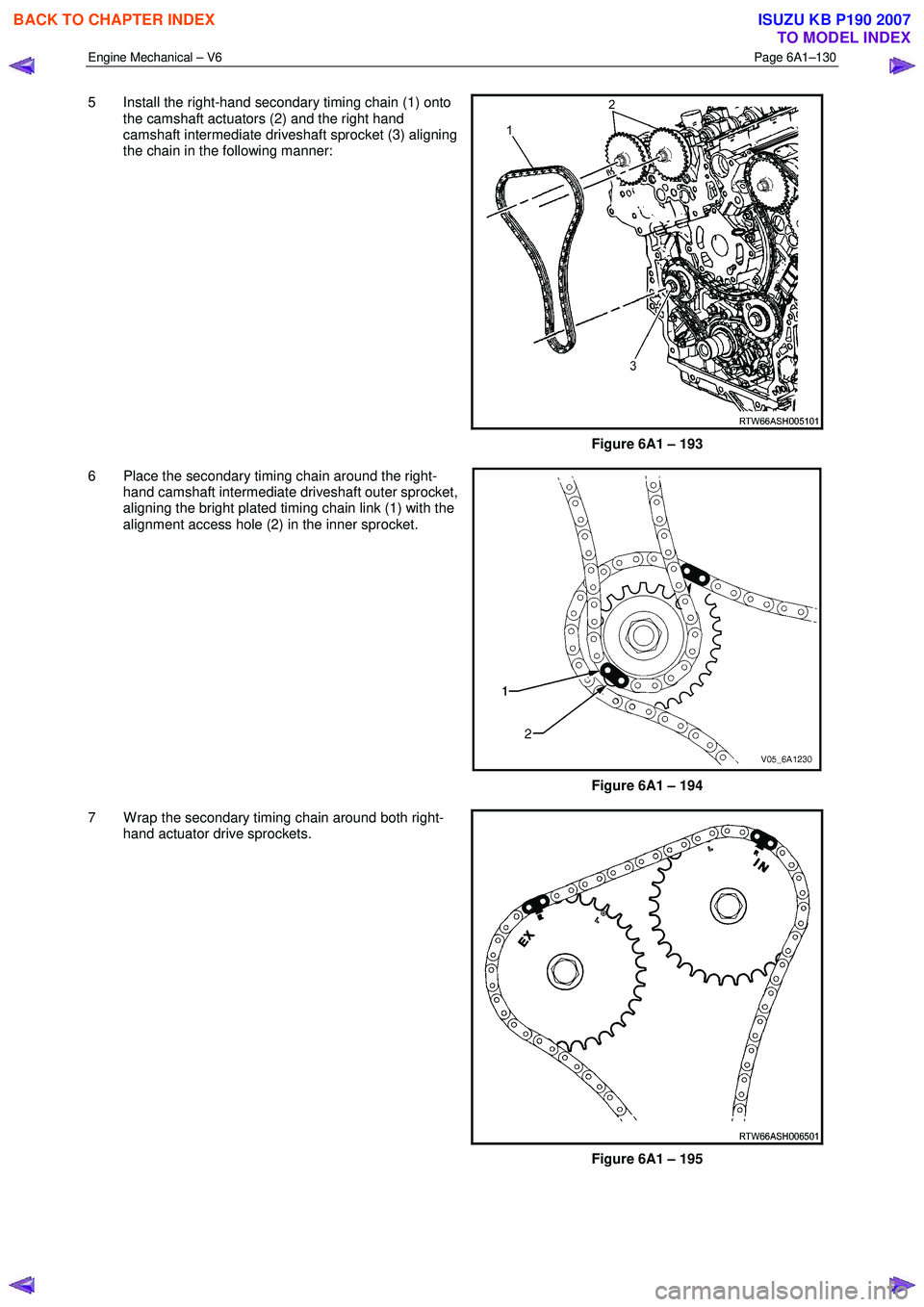
5 Install the right-hand secondary timing chain (1) onto
the camshaft actuators (2) and the right hand
camshaft intermediate driveshaft sprocket (3) aligning
the chain in the following manner:
Figure 6A1 – 193
6 Place the secondary timing chain around the right- hand camshaft intermediate driveshaft outer sprocket,
aligning the bright plated timing chain link (1) with the
alignment access hole (2) in the inner sprocket.
Figure 6A1 – 194
7 W rap the secondary timing chain around both right- hand actuator drive sprockets.
Figure 6A1 – 195
BACK TO CHAPTER INDEX
TO MODEL INDEX
ISUZU KB P190 2007
Page 2610 of 6020
Engine Mechanical – V6 Page 6A1–131
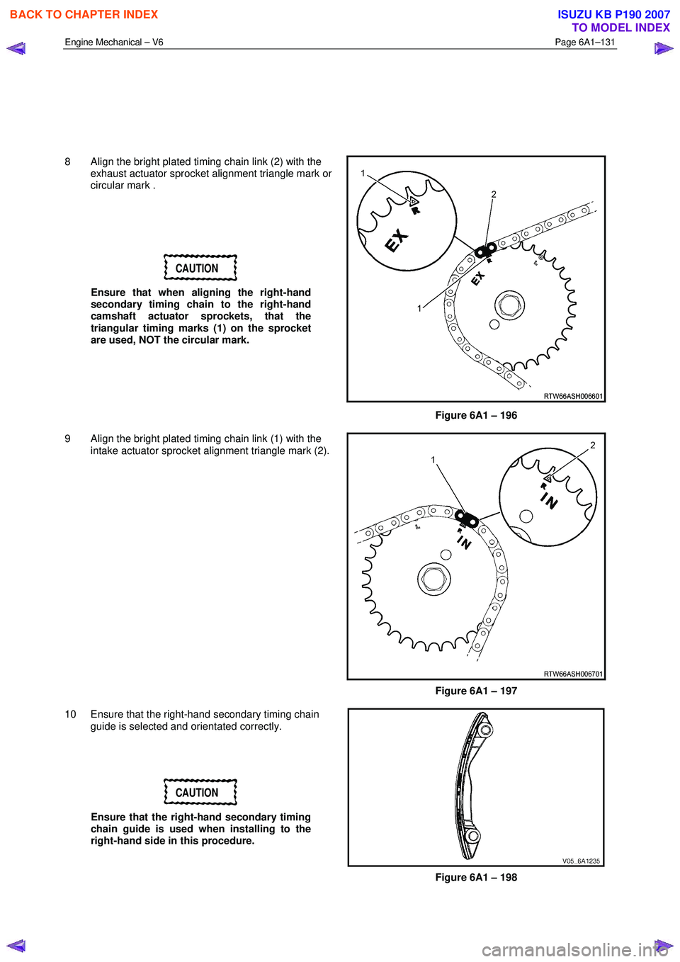
8 Align the bright plated timing chain link (2) with the exhaust actuator sprocket alignment triangle mark or
circular mark .
CAUTION
Ensure that when aligning the right-hand
secondary timing chain to the right-hand
camshaft actuator sprockets, that the
triangular timing marks (1) on the sprocket
are used, NOT the circular mark.
Figure 6A1 – 196
9 Align the bright plated timing chain link (1) with the intake actuator sprocket alignment triangle mark (2).
Figure 6A1 – 197
10 Ensure that the right-hand secondary timing chain guide is selected and orientated correctly.
CAUTION
Ensure that the right-hand secondary timing
chain guide is used when installing to the
right-hand side in this procedure.
Figure 6A1 – 198
BACK TO CHAPTER INDEX
TO MODEL INDEX
ISUZU KB P190 2007
Page 2611 of 6020
Engine Mechanical – V6 Page 6A1–132
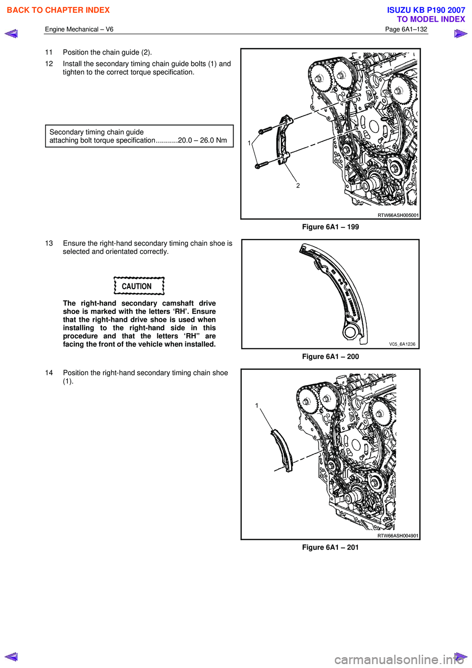
11 Position the chain guide (2).
12 Install the secondary timing chain guide bolts (1) and tighten to the correct torque specification.
Secondary timing chain guide
attaching bolt torque specification ...........20.0 – 26.0 Nm
Figure 6A1 – 199
13 Ensure the right-hand secondary timing chain shoe is selected and orientated correctly.
CAUTION
The right-hand secondary camshaft drive
shoe is marked with the letters ‘RH’. Ensure
that the right-hand drive shoe is used when
installing to the right-hand side in this
procedure and that the letters ‘RH” are
facing the front of the vehicle when installed.
Figure 6A1 – 200
14 Position the right-hand secondary timing chain shoe (1).
Figure 6A1 – 201
BACK TO CHAPTER INDEX
TO MODEL INDEX
ISUZU KB P190 2007
Page 2612 of 6020
Engine Mechanical – V6 Page 6A1–133
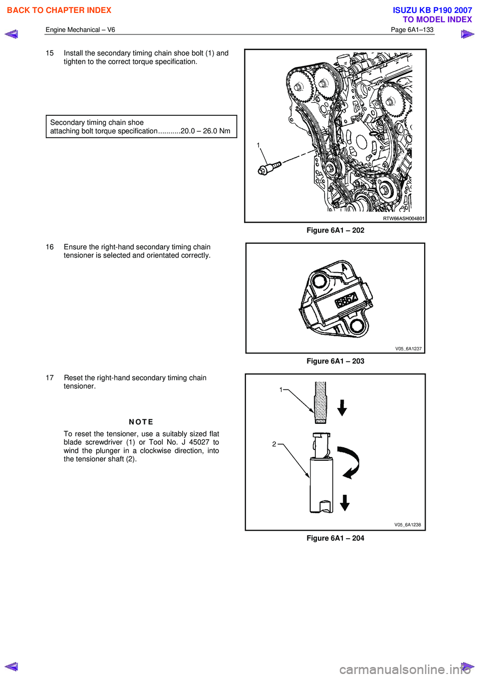
15 Install the secondary timing chain shoe bolt (1) and
tighten to the correct torque specification.
Secondary timing chain shoe
attaching bolt torque specification ...........20.0 – 26.0 Nm
Figure 6A1 – 202
16 Ensure the right-hand secondary timing chain tensioner is selected and orientated correctly.
Figure 6A1 – 203
17 Reset the right-hand secondary timing chain tensioner.
NOTE
To reset the tensioner, use a suitably sized flat
blade screwdriver (1) or Tool No. J 45027 to
wind the plunger in a clockwise direction, into
the tensioner shaft (2).
Figure 6A1 – 204
BACK TO CHAPTER INDEX
TO MODEL INDEX
ISUZU KB P190 2007
Page 2613 of 6020
Engine Mechanical – V6 Page 6A1–134
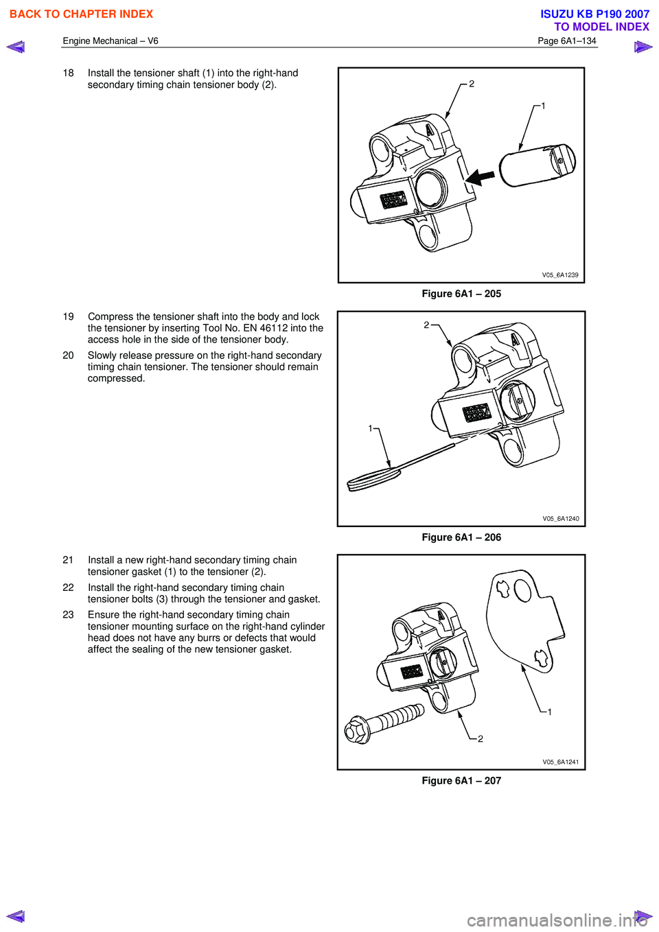
18 Install the tensioner shaft (1) into the right-hand
secondary timing chain tensioner body (2).
Figure 6A1 – 205
19 Compress the tensioner shaft into the body and lock the tensioner by inserting Tool No. EN 46112 into the
access hole in the side of the tensioner body.
20 Slowly release pressure on the right-hand secondary timing chain tensioner. The tensioner should remain
compressed.
Figure 6A1 – 206
21 Install a new right-hand secondary timing chain tensioner gasket (1) to the tensioner (2).
22 Install the right-hand secondary timing chain tensioner bolts (3) through the tensioner and gasket.
23 Ensure the right-hand secondary timing chain tensioner mounting surface on the right-hand cylinder
head does not have any burrs or defects that would
affect the sealing of the new tensioner gasket.
Figure 6A1 – 207
BACK TO CHAPTER INDEX
TO MODEL INDEX
ISUZU KB P190 2007
Page 2614 of 6020
Engine Mechanical – V6 Page 6A1–135
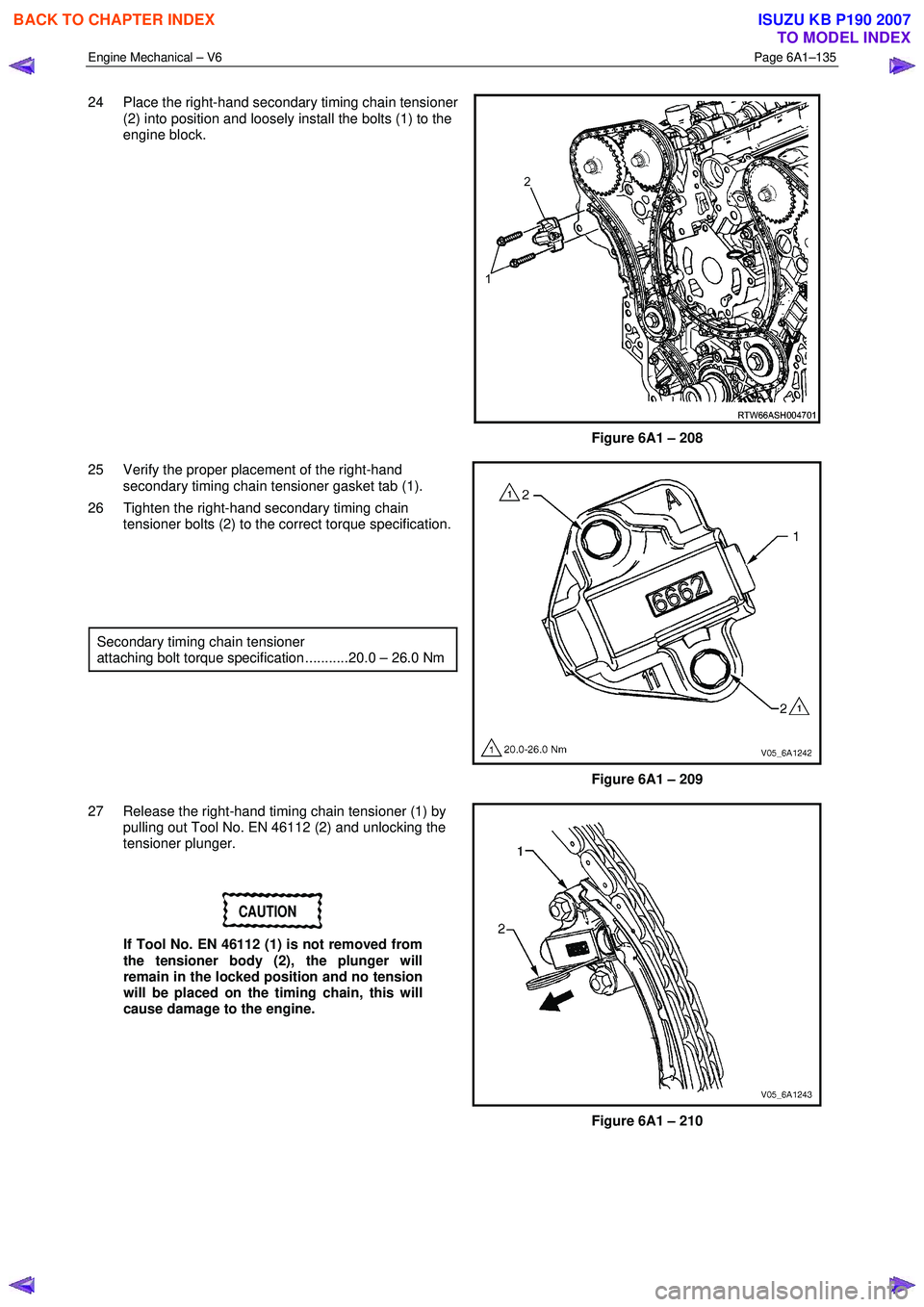
24 Place the right-hand secondary timing chain tensioner
(2) into position and loosely install the bolts (1) to the
engine block.
Figure 6A1 – 208
25 Verify the proper placement of the right-hand secondary timing chain tensioner gasket tab (1).
26 Tighten the right-hand secondary timing chain tensioner bolts (2) to the correct torque specification.
Secondary timing chain tensioner
attaching bolt torque specification ...........20.0 – 26.0 Nm
Figure 6A1 – 209
27 Release the right-hand timing chain tensioner (1) by pulling out Tool No. EN 46112 (2) and unlocking the
tensioner plunger.
CAUTION
If Tool No. EN 46112 (1) is not removed from
the tensioner body (2), the plunger will
remain in the locked position and no tension
will be placed on the timing chain, this will
cause damage to the engine.
Figure 6A1 – 210
BACK TO CHAPTER INDEX
TO MODEL INDEX
ISUZU KB P190 2007
Page 2615 of 6020
Engine Mechanical – V6 Page 6A1–136
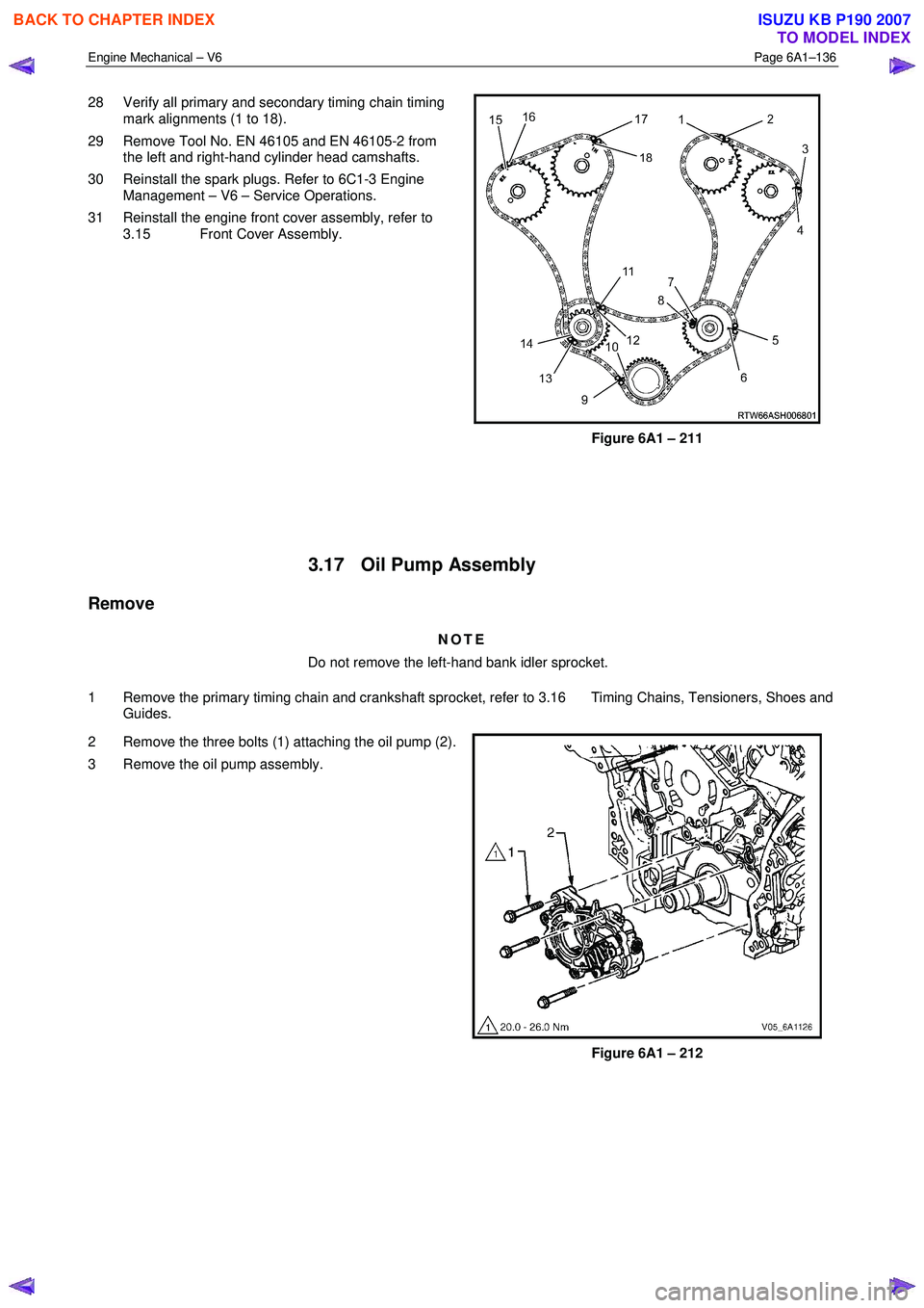
28 Verify all primary and secondary timing chain timing
mark alignments (1 to 18).
29 Remove Tool No. EN 46105 and EN 46105-2 from the left and right-hand cylinder head camshafts.
30 Reinstall the spark plugs. Refer to 6C1-3 Engine Management – V6 – Service Operations.
31 Reinstall the engine front cover assembly, refer to 3.15 Front Cover Assembly.
Figure 6A1 – 211
3.17 Oil Pump Assembly
Remove
NOTE
Do not remove the left-hand bank idler sprocket.
1 Remove the primary timing chain and crankshaft sprocket, refer to 3.16 Timing Chains, Tensioners, Shoes and Guides.
2 Remove the three bolts (1) attaching the oil pump (2).
3 Remove the oil pump assembly.
Figure 6A1 – 212
BACK TO CHAPTER INDEX
TO MODEL INDEX
ISUZU KB P190 2007
Page 2620 of 6020
Engine Mechanical – V6 Page 6A1–141
Reassemble
CAUTION
As there are no serviceable components
within the oil pump, a disassembled oil pump
must be replaced.
Reinstall
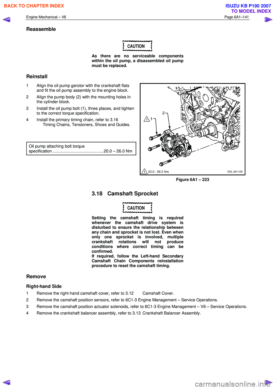
1 Align the oil pump gerotor with the crankshaft flats and fit the oil pump assembly to the engine block.
2 Align the pump body (2) with the mounting holes in the cylinder block.
3 Install the oil pump bolt (1), three places, and tighten to the correct torque specification.
4 Install the primary timing chain, refer to 3.16 Timing Chains, Tensioners, Shoes and Guides.
Oil pump attaching bolt torque
specification ............................................20.0 – 26.0 Nm
Figure 6A1 – 223
3.18 Camshaft Sprocket
CAUTION
Setting the camshaft timing is required
whenever the camshaft drive system is
disturbed to ensure the relationship between
any chain and sprocket is not lost. Even when
only one sprocket is involved, multiple
crankshaft rotations will not produce
conditions where correct timing can be
confirmed.
If required, follow the Left-hand Secondary
Camshaft Chain Components reinstallation
procedure to reset the camshaft timing.
Remove
Right-hand Side
1 Remove the right-hand camshaft cover, refer to 3.12 Camshaft Cover.
2 Remove the camshaft position sensors, refer to 6C1-3 Engine Management – Service Operations.
3 Remove the camshaft position actuator solenoids, refer to 6C1-3 Engine Management – V6 – Service Operations.
4 Remove the crankshaft balancer assembly, refer to 3.13 Crankshaft Balancer Assembly.
BACK TO CHAPTER INDEX
TO MODEL INDEX
ISUZU KB P190 2007
Page 2637 of 6020
Engine Mechanical – V6 Page 6A1–158
3.20 Rocker Arm
Remove
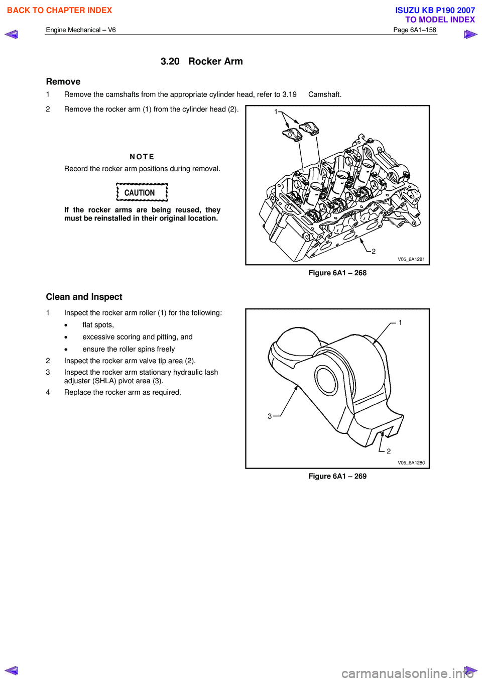
1 Remove the camshafts from the appropriate cylinder head, refer to 3.19 Camshaft.
2 Remove the rocker arm (1) from the cylinder head (2).
NOTE
Record the rocker arm positions during removal.
CAUTION
If the rocker arms are being reused, they
must be reinstalled in their original location.
Figure 6A1 – 268
Clean and Inspect
1 Inspect the rocker arm roller (1) for the following:
• flat spots,
• excessive scoring and pitting, and
• ensure the roller spins freely
2 Inspect the rocker arm valve tip area (2).
3 Inspect the rocker arm stationary hydraulic lash adjuster (SHLA) pivot area (3).
4 Replace the rocker arm as required.
Figure 6A1 – 269
BACK TO CHAPTER INDEX
TO MODEL INDEX
ISUZU KB P190 2007
Page 2640 of 6020
Engine Mechanical – V6 Page 6A1–161
Reinstall
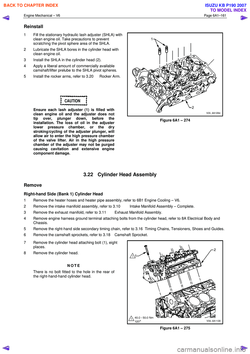
1 Fill the stationary hydraulic lash adjuster (SHLA) with
clean engine oil. Take precautions to prevent
scratching the pivot sphere area of the SHLA.
2 Lubricate the SHLA bores in the cylinder head with clean engine oil.
3 Install the SHLA in the cylinder head (2).
4 Apply a liberal amount of commercially available camshaft/lifter prelube to the SHLA pivot spheres.
5 Install the rocker arms, refer to 3.20 Rocker Arm.
CAUTION
Ensure each lash adjuster (1) is filled with
clean engine oil and the adjuster does not
tip over, plunger down, before the
installation. The loss of oil in the adjuster
lower pressure chamber, or the dry
stroking/cycling of the adjuster plunger, will
allow air to enter the high pressure chamber
of the valve lifter. Air in the high pressure
chamber of the adjuster may not be purged
causing cavitation and extensive engine
component damage.
Figure 6A1 – 274
3.22 Cylinder Head Assembly
Remove
Right-hand Side (Bank 1) Cylinder Head
1 Remove the heater hoses and heater pipe assembly, refer to 6B1 Engine Cooling – V6.
2 Remove the intake manifold assembly, refer to 3.10 Intake Manifold Assembly – Complete.
3 Remove the exhaust manifold, refer to 3.11 Exhaust Manifold Assembly.
4 Remove engine harness ground terminal attaching bolts from the cylinder head, refer to 8A Electrical Body and Chassis.
5 Remove the right-hand side secondary timing chain, refer to 3.16 Timing Chains, Tensioners, Shoes and Guides.
6 Remove the camshaft sprockets, refer to 3.18 Camshaft Sprocket.
7 Remove the cylinder head attaching bolt (1), eight places.
8 Remove the cylinder head.
NOTE
There is no bolt fitted to the hole in the rear of
the right-hand-hand cylinder head.
Figure 6A1 – 275
BACK TO CHAPTER INDEX
TO MODEL INDEX
ISUZU KB P190 2007