Circuit ISUZU KB P190 2007 Workshop Repair Manual
[x] Cancel search | Manufacturer: ISUZU, Model Year: 2007, Model line: KB P190, Model: ISUZU KB P190 2007Pages: 6020, PDF Size: 70.23 MB
Page 3727 of 6020
Powertrain Interface Module – V6 Page 6E1–66
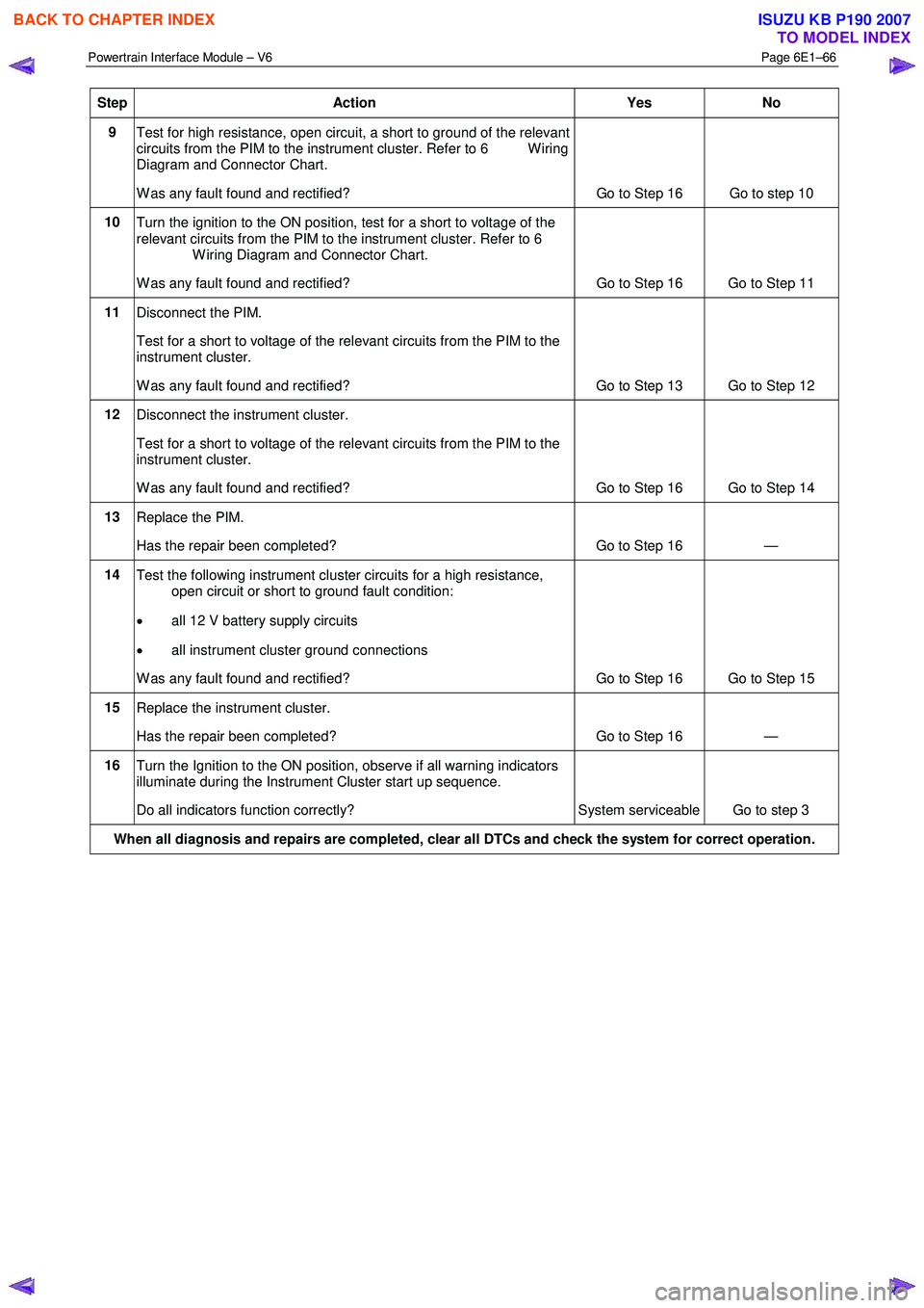
Step Action Yes No
9
Test for high resistance, open circuit, a short to ground of the relevant
circuits from the PIM to the instrument cluster. Refer to 6 W iring
Diagram and Connector Chart.
W as any fault found and rectified? Go to Step 16 Go to step 10
10
Turn the ignition to the ON position, test for a short to voltage of the
relevant circuits from the PIM to the instrument cluster. Refer to 6
W iring Diagram and Connector Chart.
W as any fault found and rectified? Go to Step 16 Go to Step 11
11
Disconnect the PIM.
Test for a short to voltage of the relevant circuits from the PIM to the
instrument cluster.
W as any fault found and rectified? Go to Step 13 Go to Step 12
12 Disconnect the instrument cluster.
Test for a short to voltage of the relevant circuits from the PIM to the
instrument cluster.
W as any fault found and rectified? Go to Step 16 Go to Step 14
13 Replace the PIM.
Has the repair been completed? Go to Step 16 —
14 Test the following instrument cluster circuits for a high resistance,
open circuit or short to ground fault condition:
• all 12 V battery supply circuits
• all instrument cluster ground connections
W as any fault found and rectified? Go to Step 16 Go to Step 15
15 Replace the instrument cluster.
Has the repair been completed? Go to Step 16 —
16 Turn the Ignition to the ON position, observe if all warning indicators
illuminate during the Instrument Cluster start up sequence.
Do all indicators function correctly? System serviceable Go to step 3
When all diagnosis and repairs are completed, clear all DTCs and check the system for correct operation.
BACK TO CHAPTER INDEX
TO MODEL INDEX
ISUZU KB P190 2007
Page 3728 of 6020
Powertrain Interface Module – V6 Page 6E1–67
10.3 Tachometer Diagnostics
Circuit Description
The powertrain interface module (PIM) receives the tachomer signal from the engine control module (ECM), it is then
sent to the instrument cluster by the PIM via a hard wired connection to drive the tachometer which displays the engine
RPM. Some of these components do not set a DTC, in the event of a component failure. The following diagnostic
procedures are devised to assist in these cases.
Additional Information
• Refer to 7.2 Diagnostic System Check to monitor DTC’s.
• Refer to 8A Electrical Body and Chassis for the following information:
• ECM wiring diagram.
• Refer to 6 W iring Diagram and Connector Chart for the following information:
• PIM connector illustration and terminal assignment, and
• PIM wiring diagram.
• For intermittent faults, refer to Intermittent Fault Conditions.
• Check for an intermittent fault in the wiring harness or connectors, if a fault cannot be found the system is
serviceable.
Since fault conditions in a wiring connector may trigger DTCs, always test the connectors related to this diagnostic
procedure for shorted terminals or poor wiring connection before replacing any component. Refer to 8A Electrical - Body
and Chassis for information on electrical fault diagnosis.
Test Description
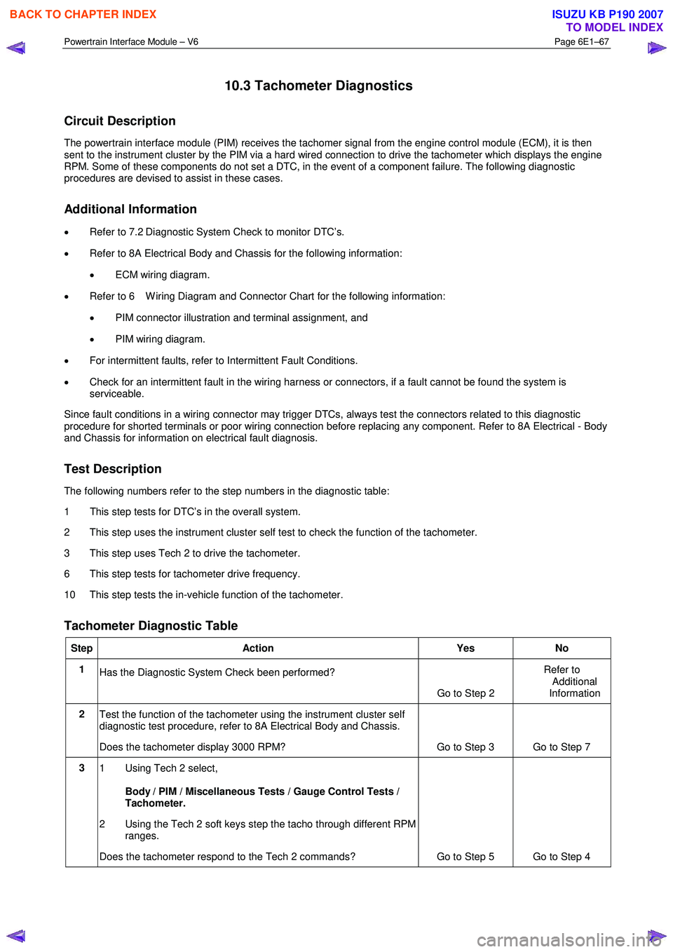
The following numbers refer to the step numbers in the diagnostic table:
1 This step tests for DTC’s in the overall system.
2 This step uses the instrument cluster self test to check the function of the tachometer.
3 This step uses Tech 2 to drive the tachometer.
6 This step tests for tachometer drive frequency.
10 This step tests the in-vehicle function of the tachometer.
Tachometer Diagnostic Table
Step Action Yes No
1
Has the Diagnostic System Check been performed?
Go to Step 2 Refer to
Additional
Information
2 Test the function of the tachometer using the instrument cluster self
diagnostic test procedure, refer to 8A Electrical Body and Chassis.
Does the tachometer display 3000 RPM? Go to Step 3 Go to Step 7
3 1 Using Tech 2 select,
Body / PIM / Miscellaneous Tests / Gauge Control Tests /
Tachometer.
2 Using the Tech 2 soft keys step the tacho through different RPM ranges.
Does the tachometer respond to the Tech 2 commands? Go to Step 5 Go to Step 4
BACK TO CHAPTER INDEX
TO MODEL INDEX
ISUZU KB P190 2007
Page 3729 of 6020
Powertrain Interface Module – V6 Page 6E1–68
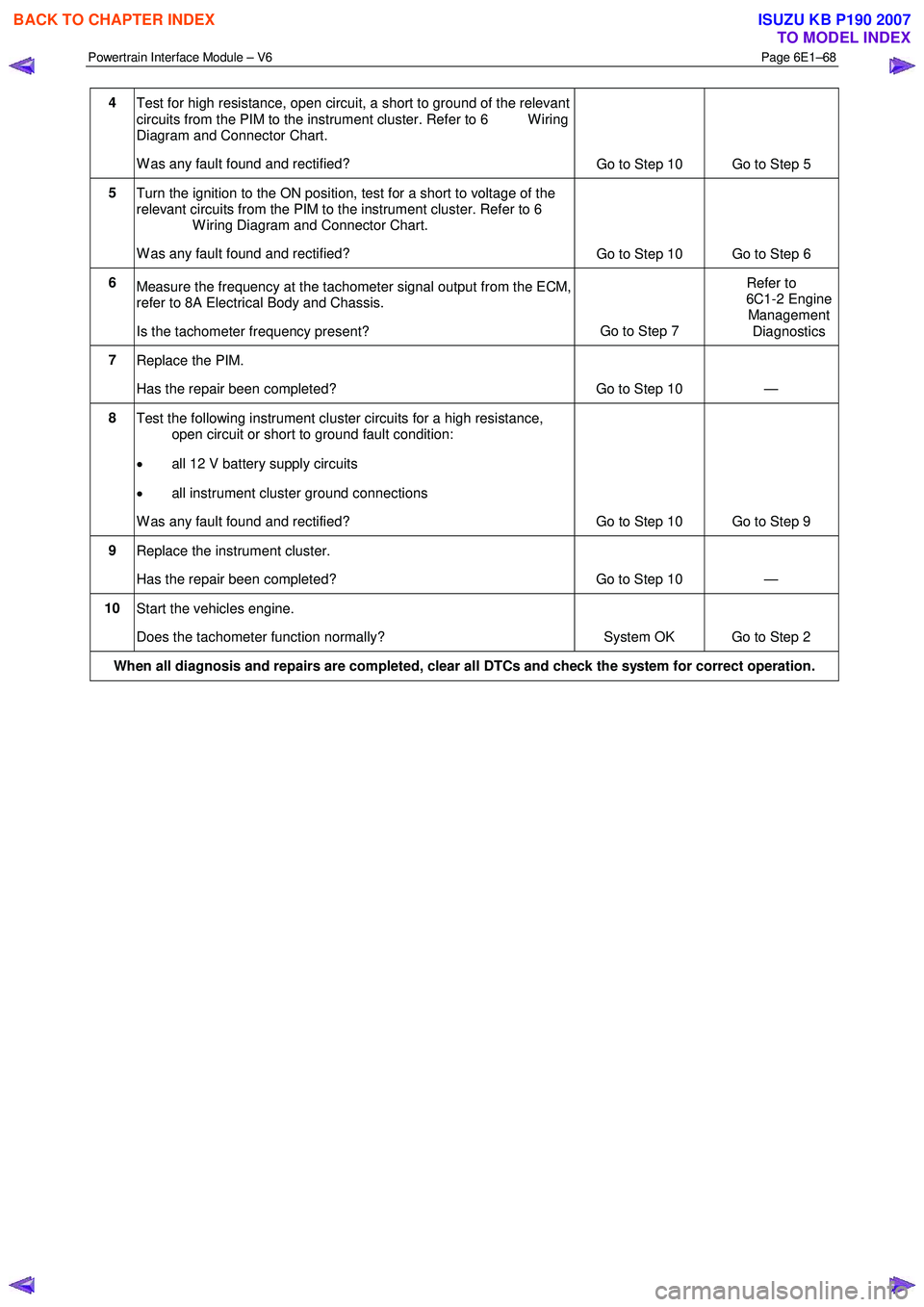
4
Test for high resistance, open circuit, a short to ground of the relevant
circuits from the PIM to the instrument cluster. Refer to 6 W iring
Diagram and Connector Chart.
W as any fault found and rectified? Go to Step 10 Go to Step 5
5
Turn the ignition to the ON position, test for a short to voltage of the
relevant circuits from the PIM to the instrument cluster. Refer to 6
W iring Diagram and Connector Chart.
W as any fault found and rectified? Go to Step 10 Go to Step 6
6
Measure the frequency at the tachometer signal output from the ECM,
refer to 8A Electrical Body and Chassis.
Is the tachometer frequency present? Go to Step 7 Refer to
6C1-2 Engine Management
Diagnostics
7 Replace the PIM.
Has the repair been completed? Go to Step 10 —
8 Test the following instrument cluster circuits for a high resistance,
open circuit or short to ground fault condition:
• all 12 V battery supply circuits
• all instrument cluster ground connections
W as any fault found and rectified? Go to Step 10 Go to Step 9
9 Replace the instrument cluster.
Has the repair been completed? Go to Step 10 —
10 Start the vehicles engine.
Does the tachometer function normally? System OK Go to Step 2
When all diagnosis and repairs are completed, clear all DTCs and check the system for correct operation.
BACK TO CHAPTER INDEX
TO MODEL INDEX
ISUZU KB P190 2007
Page 3730 of 6020
Powertrain Interface Module – V6 Page 6E1–69
10.4 Temperature Gauge Diagnostics
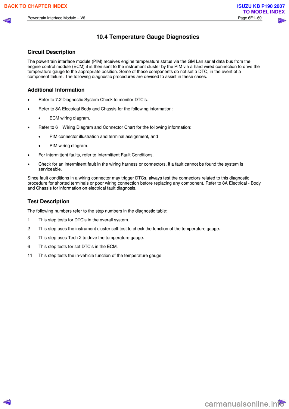
Circuit Description
The powertrain interface module (PIM) receives engine temperature status via the GM Lan serial data bus from the
engine control module (ECM) it is then sent to the instrument cluster by the PIM via a hard wired connection to drive the
temperature gauge to the appropriate position. Some of these components do not set a DTC, in the event of a
component failure. The following diagnostic procedures are devised to assist in these cases.
Additional Information
• Refer to 7.2 Diagnostic System Check to monitor DTC’s.
• Refer to 8A Electrical Body and Chassis for the following information:
• ECM wiring diagram.
• Refer to 6 W iring Diagram and Connector Chart for the following information:
• PIM connector illustration and terminal assignment, and
• PIM wiring diagram.
• For intermittent faults, refer to Intermittent Fault Conditions.
• Check for an intermittent fault in the wiring harness or connectors, if a fault cannot be found the system is
serviceable.
Since fault conditions in a wiring connector may trigger DTCs, always test the connectors related to this diagnostic
procedure for shorted terminals or poor wiring connection before replacing any component. Refer to 8A Electrical - Body
and Chassis for information on electrical fault diagnosis.
Test Description
The following numbers refer to the step numbers in the diagnostic table:
1 This step tests for DTC’s in the overall system.
2 This step uses the instrument cluster self test to check the function of the temperature gauge.
3 This step uses Tech 2 to drive the temperature gauge.
6 This step tests for set DTC’s in the ECM.
11 This step tests the in-vehicle function of the temperature gauge.
BACK TO CHAPTER INDEX
TO MODEL INDEX
ISUZU KB P190 2007
Page 3731 of 6020
Powertrain Interface Module – V6 Page 6E1–70
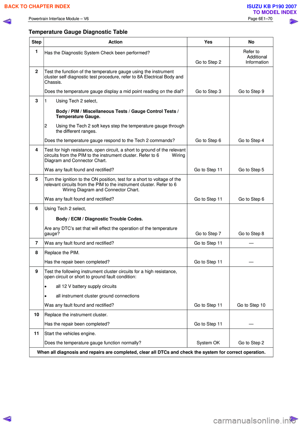
Temperature Gauge Diagnostic Table
Step Action Yes No
1
Has the Diagnostic System Check been performed?
Go to Step 2 Refer to
Additional
Information
2 Test the function of the temperature gauge using the instrument
cluster self diagnostic test procedure, refer to 8A Electrical Body and
Chassis.
Does the temperature gauge display a mid point reading on the dial? Go to Step 3 Go to Step 9
3
1 Using Tech 2 select,
Body / PIM / Miscellaneous Tests / Gauge Control Tests /
Temperature Gauge.
2 Using the Tech 2 soft keys step the temperature gauge through the different ranges.
Does the temperature gauge respond to the Tech 2 commands? Go to Step 6 Go to Step 4
4 Test for high resistance, open circuit, a short to ground of the relevant
circuits from the PIM to the instrument cluster. Refer to 6 W iring
Diagram and Connector Chart.
W as any fault found and rectified? Go to Step 11 Go to Step 5
5 Turn the ignition to the ON position, test for a short to voltage of the
relevant circuits from the PIM to the instrument cluster. Refer to 6
W iring Diagram and Connector Chart.
W as any fault found and rectified? Go to Step 11 Go to Step 6
6
Using Tech 2 select,
Body / ECM / Diagnostic Trouble Codes.
Are any DTC’s set that will effect the operation of the temperature
gauge? Go to Step 7 Go to Step 8
7 W as any fault found and rectified? Go to Step 11 —
8 Replace the PIM.
Has the repair been completed? Go to Step 11 —
9 Test the following instrument cluster circuits for a high resistance,
open circuit or short to ground fault condition:
• all 12 V battery supply circuits
• all instrument cluster ground connections
W as any fault found and rectified? Go to Step 11 Go to Step 10
10 Replace the instrument cluster.
Has the repair been completed? Go to Step 11 —
11 Start the vehicles engine.
Does the temperature gauge function normally? System OK Go to Step 2
When all diagnosis and repairs are completed, clear all DTCs and check the system for correct operation.
BACK TO CHAPTER INDEX
TO MODEL INDEX
ISUZU KB P190 2007
Page 3732 of 6020
Powertrain Interface Module – V6 Page 6E1–71
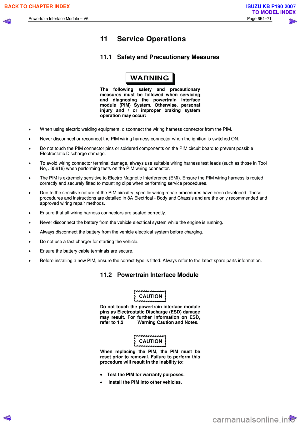
11 Service Operations
11.1 Safety and Precautionary Measures
The following safety and precautionary
measures must be followed when servicing
and diagnosing the powertrain interface
module (PIM) System. Otherwise, personal
injury and / or improper braking system
operation may occur:
• W hen using electric welding equipment, disconnect the wiring harness connector from the PIM.
• Never disconnect or reconnect the PIM wiring harness connector when the ignition is switched ON.
• Do not touch the PIM connector pins or soldered components on the PIM circuit board to prevent possible
Electrostatic Discharge damage.
• To avoid wiring connector terminal damage, always use suitable wiring harness test leads (such as those in Tool
No, J35616) when performing tests on the PIM wiring connector.
• The PIM is extremely sensitive to Electro Magnetic Interference (EMI). Ensure the PIM wiring harness is routed
correctly and securely fitted to mounting clips when performing service procedures.
• Due to the sensitive nature of the PIM circuitry, specific wiring repair procedures have been developed. These
procedures and instructions are detailed in 8A Electrical - Body and Chassis and are the only recommended and
approved wiring repair methods.
• Ensure that all wiring harness connectors are seated correctly.
• Never disconnect the battery from the vehicle electrical system while the engine is running.
• Always disconnect the battery from the vehicle electrical system before charging.
• Do not use a fast charger for starting the vehicle.
• Ensure the battery cable terminals are secure.
• Before installing a new PIM, ensure the correct type is fitted. Always refer to the latest spare parts information.
11.2 Powertrain Interface Module
Do not touch the powertrain interface module
pins as Electrostatic Discharge (ESD) damage
may result. For further information on ESD,
refer to 1.2 Warning Caution and Notes.
When replacing the PIM, the PIM must be
reset prior to removal. Failure to perform this
procedure will result in the inability to:
• Test the PIM for warranty purposes.
• Install the PIM into other vehicles.
BACK TO CHAPTER INDEX
TO MODEL INDEX
ISUZU KB P190 2007
Page 3748 of 6020
Powertrain Interface Module – V6 Page 6E1–87
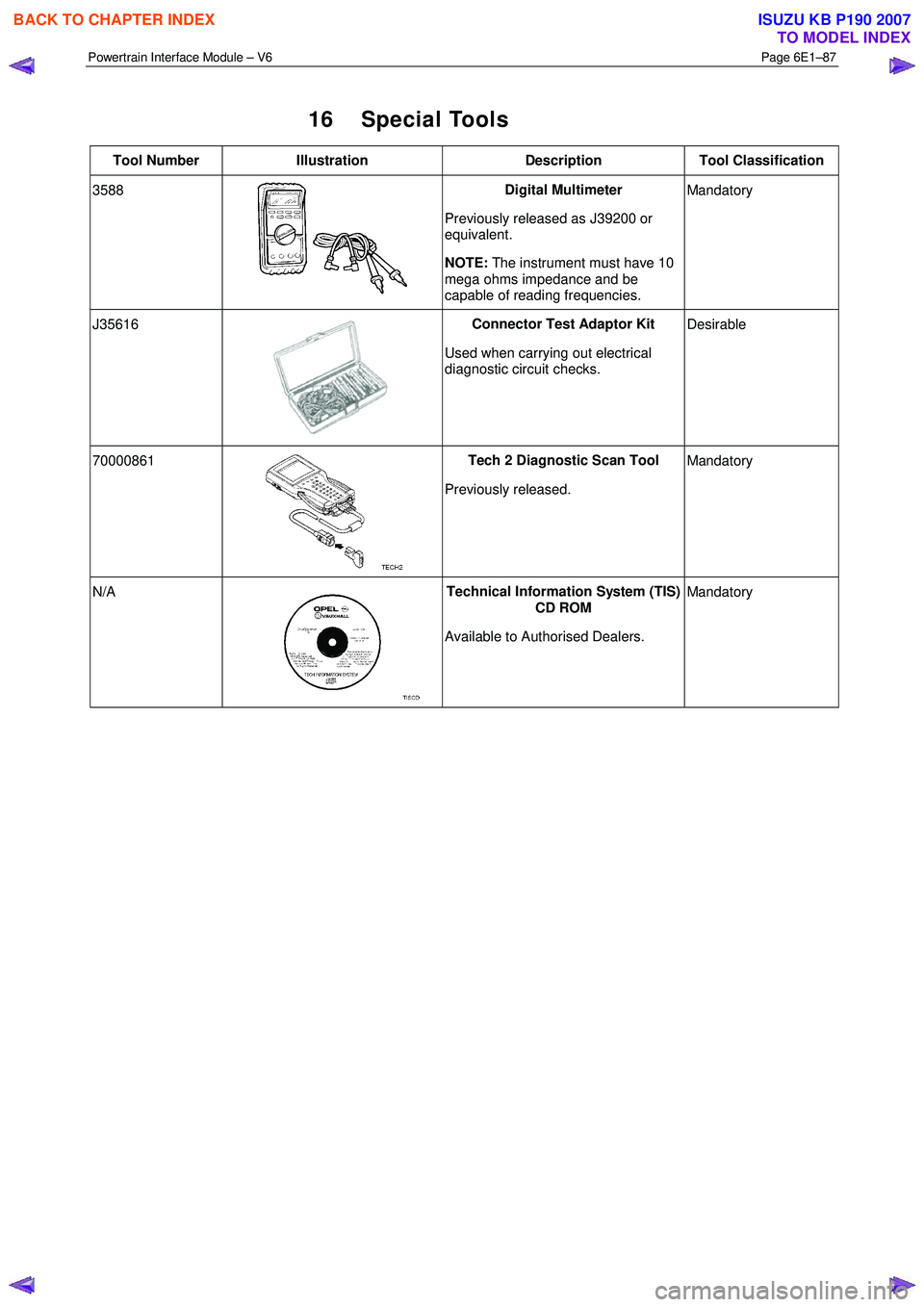
16 Special Tools
Tool Number Illustration Description Tool Classification
3588
Digital Multimeter
Previously released as J39200 or
equivalent.
NOTE: The instrument must have 10
mega ohms impedance and be
capable of reading frequencies. Mandatory
J35616
Connector Test Adaptor Kit
Used when carrying out electrical
diagnostic circuit checks.
Desirable
70000861
Tech 2 Diagnostic Scan Tool
Previously released. Mandatory
N/A
Technical Information System (TIS)
CD ROM
Available to Authorised Dealers. Mandatory
BACK TO CHAPTER INDEX
TO MODEL INDEX
ISUZU KB P190 2007
Page 3764 of 6020
Automatic Transmission – 4L60E – General Information Page 7C1–4
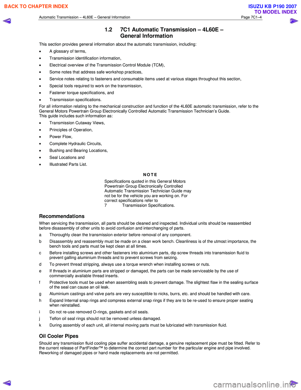
1.2 7C1 Automatic Transmission – 4L60E –
General Information
This section provides general information about the automatic transmission, including:
• A glossary of terms,
• Transmission identification information,
• Electrical overview of the Transmission Control Module (TCM),
• Some notes that address safe workshop practices,
• Service notes relating to fasteners and consumable items used at various stages throughout this section,
• Special tools required to work on the transmission,
• Fastener torque specifications, and
• Transmission specifications.
For all information relating to the mechanical construction and function of the 4L60E automatic transmission, refer to the
General Motors Powertrain Group Electronically Controlled Automatic Transmission Technician’s Guide.
This guide includes such information as:
• Transmission Cutaway Views,
• Principles of Operation,
• Power Flow,
• Complete Hydraulic Circuits,
• Bushing and Bearing Locations,
• Seal Locations and
• Illustrated Parts List.
NOTE
Specifications quoted in this General Motors
Powertrain Group Electronically Controlled
Automatic Transmission Technician Guide may
not be for the vehicle you are working on. For
correct specifications refer to
7 Transmission Specifications.
Recommendations
When servicing the transmission, all parts should be cleaned and inspected. Individual units should be reassembled
before disassembly of other units to avoid confusion and interchanging of parts.
a Thoroughly clean the transmission exterior before removal of any component.
b Disassembly and reassembly must be made on a clean work bench. Cleanliness is of the utmost importance, the bench tools and parts must be kept clean at all times.
c Before installing screws and other fasteners into aluminium parts, dip screw threads into transmission fluid to prevent galling aluminium threads and to prevent screws from seizing.
d To prevent thread stripping, always use a torque wrench when installing screws or nuts.
e If threads in aluminium parts are stripped or damaged, the parts can be made serviceable by the use of commercially available thread inserts.
f Protective tools must be used when assembling seals to prevent damage. The slightest flaw in the sealing surface of the seal can cause an oil leak.
g Aluminium castings and valve parts are very susceptible to nicks, burrs, etc. and should be handled with care.
h Expand Internal snap rings and compress external snap rings if they are to be re-used to ensure proper seating when reinstalled.
i Do not re-use removed O-rings, gaskets and oil seals.
j Teflon oil seal rings should not be removed unless damaged.
k During assembly of each unit, all internal moving parts must be lubricated with transmission fluid.
Oil Cooler Pipes
Should any transmission fluid cooling pipe suffer accidental damage, a genuine replacement pipe must be fitted. Refer to
the current release of PartFinder™ to determine the correct part number for the particular engine and pipe involved.
Reworking of damaged pipes or hand made replacements are not permitted.
BACK TO CHAPTER INDEX
TO MODEL INDEX
ISUZU KB P190 2007
Page 3765 of 6020
Automatic Transmission – 4L60E – General Information Page 7C1–5
Clean and Inspect
Do not use solvents on neoprene seals,
composition faced clutch plates or thrust
washers as damage to parts may occur.
After complete disassembly of a component, wash all metal parts in a clean solvent and dry with compressed air. Blow
oil passages out and check to make sure they are not obstructed, small passages should be checked with tag wire. All
parts should be inspected to determine if replacement is required.
Pay particular attention to the following:
• Inspect linkage and pivot points for excessive wear.
• Bearing and thrust surfaces of all parts should be checked for excessive wear and scoring.
• Check for broken seal rings, damaged ring lands and damaged threads.
• Inspect seals for damage.
• Mating surfaces of castings should be checked for burrs. Irregularities may be removed by lapping the surface with
emery paper laid on a flat surface, such as a piece of plate glass.
• Castings should be checked for cracks and porosity.
1.3 7C2 Automatic Transmission – 4L60E –
Electrical Diagnosis
For transmissions fitted to V6 engines, the electrical diagnosis is in this Section. A new electrical circuit and control
module has been introduced for automatic transmissions fitted to the V6 engines.
1.4 7C3 Automatic Transmission – 4L60E – Hydraulic and Mechanical Diagnosis
Information contained in 7C3 Automatic Transmission – 4L60E – Hydraulic and Mechanical Diagnosis will assist in the
diagnosis of the mechanical and hydraulic components in the 4L60E automatic transmission, while the transmission
remains installed on the vehicle.
Examples of the type of diagnostic information contained within this section are:
• transmission functional test,
• line pressure information,
• transmission fluid diagnosis,
• symptom diagnosis and
• shift speed charts.
1.5 7C4 Automatic Transmission – 4L60E –
On-vehicle Servicing
Information in 7C4 Automatic Transmission – 4L60E – On-vehicle Servicing covers transmission fluid level checking, as
well as specific information for servicing some components while the transmission remains installed on the vehicle. This
Section also covers the transmission removal and reinstallation to the vehicle.
BACK TO CHAPTER INDEX
TO MODEL INDEX
ISUZU KB P190 2007
Page 3772 of 6020
Automatic Transmission – 4L60E – General Information Page 7C1–12
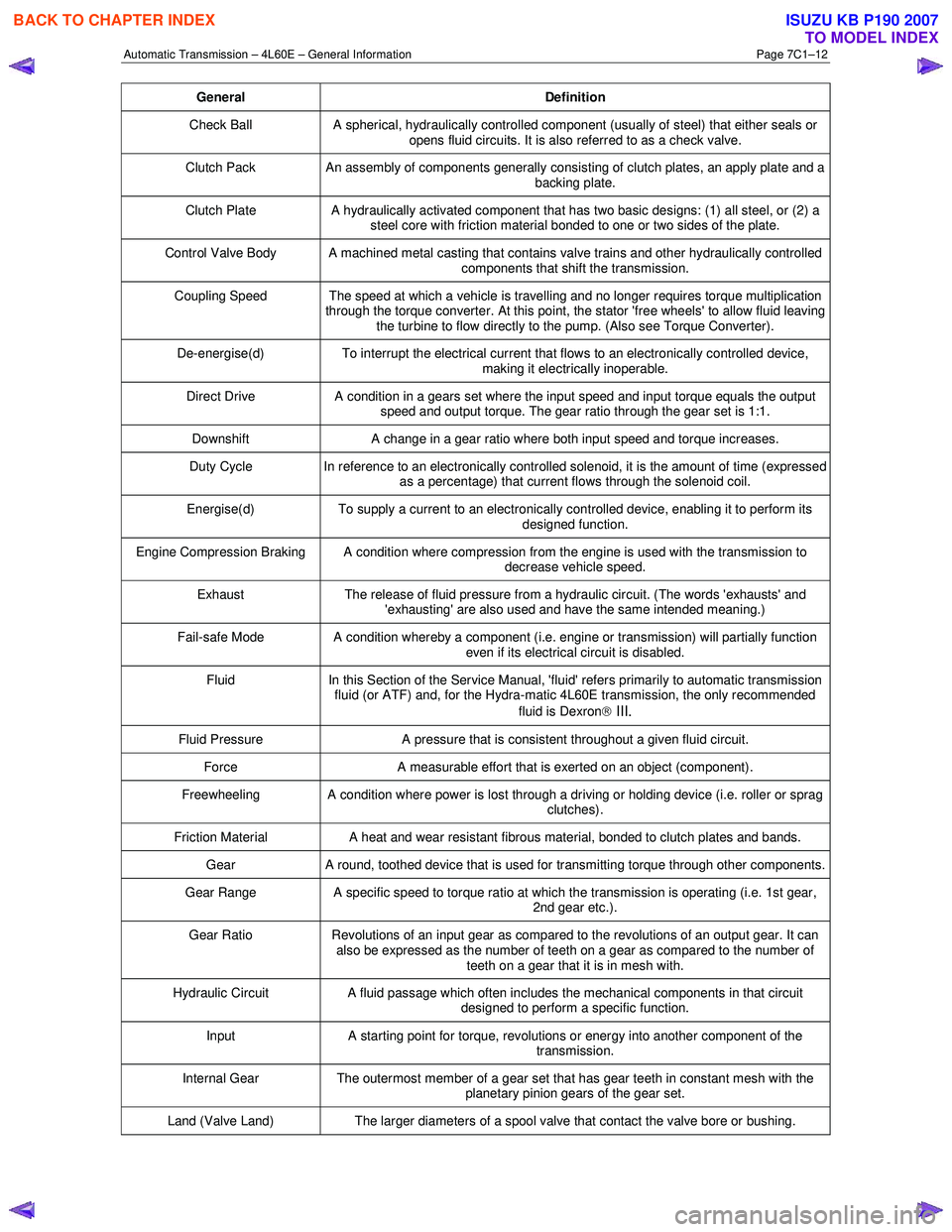
General Definition
Check Ball A spherical, hydraulically controlled component (usually of steel) that either seals or
opens fluid circuits. It is also referred to as a check valve.
Clutch Pack An assembly of components generally consisting of clutch plates, an apply plate and a
backing plate.
Clutch Plate A hydraulically activated component that has two basic designs: (1) all steel, or (2) a
steel core with friction material bonded to one or two sides of the plate.
Control Valve Body A machined metal casting that contains valve trains and other hydraulically controlled components that shift the transmission.
Coupling Speed The speed at which a vehicle is travelling and no longer requires torque multiplication through the torque converter. At this point, the stator 'free wheels' to allow fluid leaving
the turbine to flow directly to the pump. (Also see Torque Converter).
De-energise(d) To interrupt the electrical current that flows to an electronically controlled device,
making it electrically inoperable.
Direct Drive A condition in a gears set where the input speed and input torque equals the output
speed and output torque. The gear ratio through the gear set is 1:1.
Downshift A change in a gear ratio where both input speed and torque increases.
Duty Cycle In reference to an electronically controlled solenoid, it is the amount of time (expressed
as a percentage) that current flows through the solenoid coil.
Energise(d) To supply a current to an electronically controlled device, enabling it to perform its
designed function.
Engine Compression Braking A condition where compression from the engine is used with the transmission to decrease vehicle speed.
Exhaust The release of fluid pressure from a hydraulic circuit. (The words 'exhausts' and
'exhausting' are also used and have the same intended meaning.)
Fail-safe Mode A condition whereby a component (i.e. engine or transmission) will partially function even if its electrical circuit is disabled.
Fluid In this Section of the Service Manual, 'fluid' refers primarily to automatic transmission
fluid (or ATF) and, for the Hydra-matic 4L60E transmission, the only recommended
fluid is Dexron
III.
Fluid Pressure A pressure that is consistent throughout a given fluid circuit.
Force A measurable effort that is exerted on an object (component).
Freewheeling A condition where power is lost through a driving or holding device (i.e. roller or sprag
clutches).
Friction Material A heat and wear resistant fibrous material, bonded to clutch plates and bands.
Gear A round, toothed device that is used for transmitting torque through other components.
Gear Range A specific speed to torque ratio at which the transmission is operating (i.e. 1st gear,
2nd gear etc.).
Gear Ratio Revolutions of an input gear as compared to the revolutions of an output gear. It can
also be expressed as the number of teeth on a gear as compared to the number of
teeth on a gear that it is in mesh with.
Hydraulic Circuit A fluid passage which often includes the mechanical components in that circuit
designed to perform a specific function.
Input A starting point for torque, revolutions or energy into another component of the
transmission.
Internal Gear The outermost member of a gear set that has gear teeth in constant mesh with the
planetary pinion gears of the gear set.
Land (Valve Land) The larger diameters of a spool valve that contact the valve bore or bushing.
BACK TO CHAPTER INDEX
TO MODEL INDEX
ISUZU KB P190 2007