seats ISUZU KB P190 2007 Workshop Repair Manual
[x] Cancel search | Manufacturer: ISUZU, Model Year: 2007, Model line: KB P190, Model: ISUZU KB P190 2007Pages: 6020, PDF Size: 70.23 MB
Page 4 of 6020
0A-2 GENERAL INFORMATION
GENERAL REPAIR INSTRUCTIONS
1. Park the vehicle on level ground and chock the front or rear wheels before lifting the vehicle.
2. Raise the vehicle with a jack set against the axle or the frame.
3. Support the vehicle on chassis stands.
4. Use covers on the vehicle body, seats, and floor to prevent damage and/or contamination.
5. Disconnect the grounding cable from the battery before performing service operations.
This will prevent cable damage or burning due to short circuiting.
6. Handle brake fluid and antifreeze solution with great care.
Spilling these liquids on painted surfaces will damage the paint.
7. The use of the proper tool(s) and special tool(s) where specified is essential to efficient, reliable, and safe
service operations.
8. Always use genuine ISUZU replacement parts.
9. Discard used cotter pins, gaskets, O-rings, oil seals, lock washers, and self-locking nuts at disassembly.
Normal function of these parts cannot be guaranteed if they are reused.
10. Prepare new cotter pins, gaskets, O-rings, oil seals, lock washers, and self-locking nuts for installation.
11. Keep the disassembled parts neatly in groups. This will facilitate smooth and correct reassembly.
12. Keep fixing nuts and bolts separate. Fixing nuts and bolts vary in hardness and design according to installation position.
13. Clean all parts before inspection or reassembly.
14. Clean the oil ports and other openings with compressed air to make certain that they are free from dirt and obstructions.
15. Lubricate the rotating and sliding faces of all moving parts with oil or grease before installation.
16. Use the recommended liquid gasket to prevent leakage.
17. Carefully observe all nut and bolt torque specifications.
18. W hen removing or replacing parts that require refrigerant to the discharged from the air conditioning system, be sure to use the Vehicle Refrigerant Recovery and Recycling Equipment (VRRRE) to recover and recycle R134a,
to promote the aim of the protection of the ozone layer covering the earth.
19. Check and recheck your work. No service operation is complete until you have done this.
BACK TO CHAPTER INDEX
TO MODEL INDEX
ISUZU KB P190 2007
Page 547 of 6020
FRONT WHEEL DRIVE 4C1-43
Important Operations
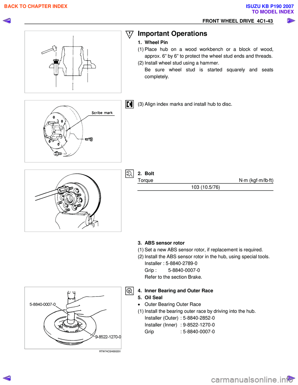
1. Wheel Pin
(1) Place hub on a wood workbench or a block of wood, approx. 6” by 6” to protect the wheel stud ends and threads.
(2) Install wheel stud using a hammer.
Be sure wheel stud is started squarely and seats completely.
(3) Align index marks and install hub to disc.
2. Bolt
Torque N ⋅m (kgf ⋅m/lb ⋅ft)
103 (10.5/76)
3. ABS sensor rotor
(1) Set a new ABS sensor rotor, if replacement is required.
(2) Install the ABS sensor rotor in the hub, using special tools.
Installer : 5-8840-2789-0
Grip : 5-8840-0007-0
Refer to the section Brake.
RTW 74CSH000201
4. Inner Bearing and Outer Race
5. Oil Seal
• Outer Bearing Outer Race
(1) Install the bearing outer race by driving into the hub.
Installer (Outer) : 5-8840-2852-0
Installer (Inner) : 9-8522-1270-0
Grip : 5-8840-0007-0
BACK TO CHAPTER INDEX
TO MODEL INDEX
ISUZU KB P190 2007
Page 554 of 6020
4C1-50 FRONT WHEEL DRIVE
Important Operations
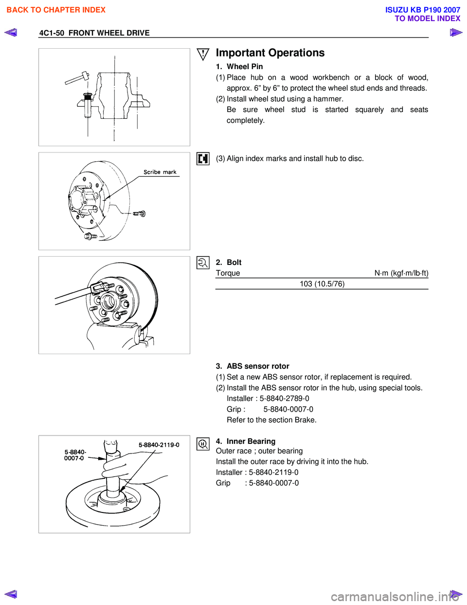
1. Wheel Pin
( 1 ) Place hub on a wood workbench or a block of wood,
approx. 6” by 6” to protect the wheel stud ends and threads.
(2) Install wheel stud using a hammer.
Be sure wheel stud is started squarely and seats completely.
(3) Align index marks and install hub to disc.
2. Bolt
Torque N ⋅m (kgf ⋅m/lb ⋅ft)
1 03 ( 10.5/76)
3. ABS sensor rotor
( 1 ) Set a new ABS sensor rotor, if replacement is required.
(2) Install the ABS sensor rotor in the hub, using special tools.
Installer : 5-8840-2789-0
Grip : 5-8840-0007-0
Refer to the section Brake.
4. Inner Bearing
Outer race ; outer bearing
Install the outer race by driving it into the hub.
Installer : 5-8840-2 119-0
Grip : 5-8840-0007-0
BACK TO CHAPTER INDEX
TO MODEL INDEX
ISUZU KB P190 2007
Page 563 of 6020
FRONT WHEEL DRIVE 4C1-59
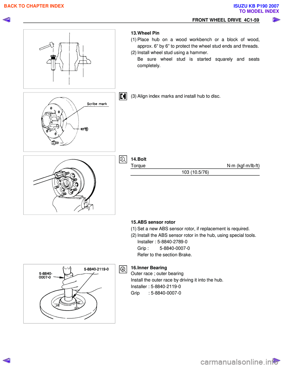
13. Wheel Pin
( 1 ) Place hub on a wood workbench or a block of wood,
approx. 6” by 6” to protect the wheel stud ends and threads.
(2) Install wheel stud using a hammer.
Be sure wheel stud is started squarely and seats completely.
(3) Align index marks and install hub to disc.
14. Bolt
Torque N ⋅m (kgf ⋅m/lb ⋅ft)
1 03 ( 10.5/76)
15. ABS sensor rotor
( 1 ) Set a new ABS sensor rotor, if replacement is required.
(2) Install the ABS sensor rotor in the hub, using special tools.
Installer : 5-8840-2789-0
Grip : 5-8840-0007-0
Refer to the section Brake.
16. Inner Bearing
Outer race ; outer bearing
Install the outer race by driving it into the hub.
Installer : 5-8840-2 119-0
Grip : 5-8840-0007-0
BACK TO CHAPTER INDEX
TO MODEL INDEX
ISUZU KB P190 2007
Page 2225 of 6020

ENGINE DRIVEABILITY AND EMISSIONS 6E–55
Low or high spark plug installation torque or improper
seating can result in the spark plug running too hot and
can cause excessive center electrode wear. The plug
and the cylinder head seats must be in good contact for
proper heat transfer and spark plug cooling. Dirty or
damaged threads in the head or on the spark plug can
keep it from seating even though the proper torque is
applied. Once spark plugs are properly seated, tighten
them to the torque shown in the Specifications Table.
Low torque may result in poor contact of the seats due
to a loose spark plug. Over tightening may cause the
spark plug shell to be stretched and will result in poor
contact between the seats. In extreme cases, exhaust
blow-by and damage beyond simple gap wear may
occur.
Cracked or broken insulators may be the result of
improper installation, damage during spark plug re-
gapping, or heat shock to the insulator material. Upper
insulators can be broken when a poorly fitting tool is
used during installation or removal, when the spark plug
is hit from the outside, or is dropped on a hard surface.
Cracks in the upper insulator may be inside the shell
and not visible. Also, the breakage may not cause
problems until oil or moisture penetrates the crack later. A broken or cracked lower insulator tip (around the
center electrode) may result from damage during re-
gapping or from “heat shock” (spark plug suddenly
operating too hot).
• Damage during re-gapping can happen if the gapping tool is pushed against the center electrode or the
insulator around it, causing the insulator to crack.
When re-gapping a spark plug, make the adjustment
by bending only the ground side terminal, keeping the
tool clear of other parts.
• “Heat shock” breakage in the lower insulator tip generally occurs during several engine operating
conditions (high speeds or heavy loading) and may
be caused by over-advanced timing or low grade
fuels. Heat shock refers to a rapid increase in the tip
temperature that causes the insulator material to
crack.
Spark plugs with less than the recommended amount of
service can sometimes be cleaned and re-gapped, then
BACK TO CHAPTER INDEX
TO MODEL INDEX
ISUZU KB P190 2007
Page 2487 of 6020

Engine Mechanical – V6 Page 6A1–8
1 General Information
The HFV6 engine features a closed vee, deep skirt die cast aluminium cylinder block with cast iron cylinder liners,
internally balanced crankcase, full length water jackets and six bolt main bearing caps.
The cylinders are arranged in two banks of three with a 60 degree included angle between the two banks.
The right-hand bank of cylinders consists of number 1-3-5
cylinders and the left-hand bank of cylinders consists of
number 2-4-6.
The engine firing order is 1-2-3-4-5-6.
Each aluminium cylinder head is fitted with hardened valve
seats and four valves per cylinder: two intake and two
exhaust.
The valves are operated by two camshafts (DOHC) per
cylinder bank, one each for intake and exhaust valves.
The crankshaft is manufactured from forged steel. A reluctor
wheel is pressed in place onto the rear of the crankshaft for
the crankshaft position sensor.
The connecting rods are manufactured from powdered
metal and the rod cap is separated during the manufacturing
process using the fractured method. This creates a stronger,
visually seamless rod to cap union.
Figure 6A1 – 1
1.1 WARNING, CAUTION and NOTES
This Section contains various W ARNINGS, CAUTIONS and NOTE statements that you must observe carefully to reduce
the risk of death or injury during service, repair procedures or vehicle operation. Incorrect service or repair procedures
may damage the vehicle or cause operational faults. W ARNINGS, CAUTION and NOTE statements are not exhaustive.
HOLDEN LTD can not possibly warn of all the potentially hazardous consequences of failure to follow these instructions.
Definition of WARNING, CAUTION and NOTE Statements
Diagnosis and repair procedures in this Section contain both general and specific W ARNING, CAUTION and NOTE
statements. HOLDEN LTD is dedicated to the presentation of service information that helps the technician to diagnose
and repair the systems necessary for proper operation of the vehicle. Certain procedures may present a hazard to the
technician if they are not followed in the recommended manner. W ARNING, CAUTION and NOTE statements are
designed to help prevent these hazards from occurring, but not all hazards can be foreseen.
WARNING defined
A W ARNING statement immediately precedes an operating procedure or maintenance practice which, if not correctly
followed, could result in death or injury. A W ARNING statement alerts you to take necessary action or not to take a
prohibited action. If a W ARNING statement is ignored, the following consequences may occur:
• Death or injury to the technician or other personnel working on the vehicle,
• Death or injury to other people in or near the workplace area, and / or
• Death or injury to the driver / or passenger(s) of the vehicle or other people, if the vehicle has been improperly
repaired.
CAUTION defined
A CAUTION statement immediately precedes an operating procedure or maintenance practice which, if not correctly
followed, could result in damage to or destruction of equipment, or corruption of data. If a CAUTION statement is ignored,
the following consequences may occur:
• Damage to the vehicle,
• Unnecessary vehicle repairs or component replacement,
• Faulty operation or performance of any system or component being repaired,
• Damage to any system or components which depend on the proper operation of the system or component being
repaired,
BACK TO CHAPTER INDEX
TO MODEL INDEX
ISUZU KB P190 2007
Page 2638 of 6020

Engine Mechanical – V6 Page 6A1–159
Reinstall
1 Apply a liberal amount of commercially available
camshaft / lifter prelube or equivalent to the pivot
pocket (1), roller (2) and valve slot (3) areas of the
camshaft followers.
Figure 6A1 – 270
2 Place the rocker arm in position on the valve tip and stationary hydraulic lash adjuster (SHLA). The
rounded head end of the arm seats on the SHLA
while the flat end seats on the valve tip.
CAUTION
• The rocker arm (1) must be positioned
squarely on the valve tip so the full width
of the roller will completely contact the
camshaft lobe.
• If the rocker arms are being reused, they
must be reinstalled in their original
location.
3 Clean the camshaft journals and carriers with a clean, lint-free cloth.
4 Reinstall the camshafts, refer to 3.19 Camshaft.
Figure 6A1 – 271
BACK TO CHAPTER INDEX
TO MODEL INDEX
ISUZU KB P190 2007
Page 2651 of 6020
Engine Mechanical – V6 Page 6A1–172
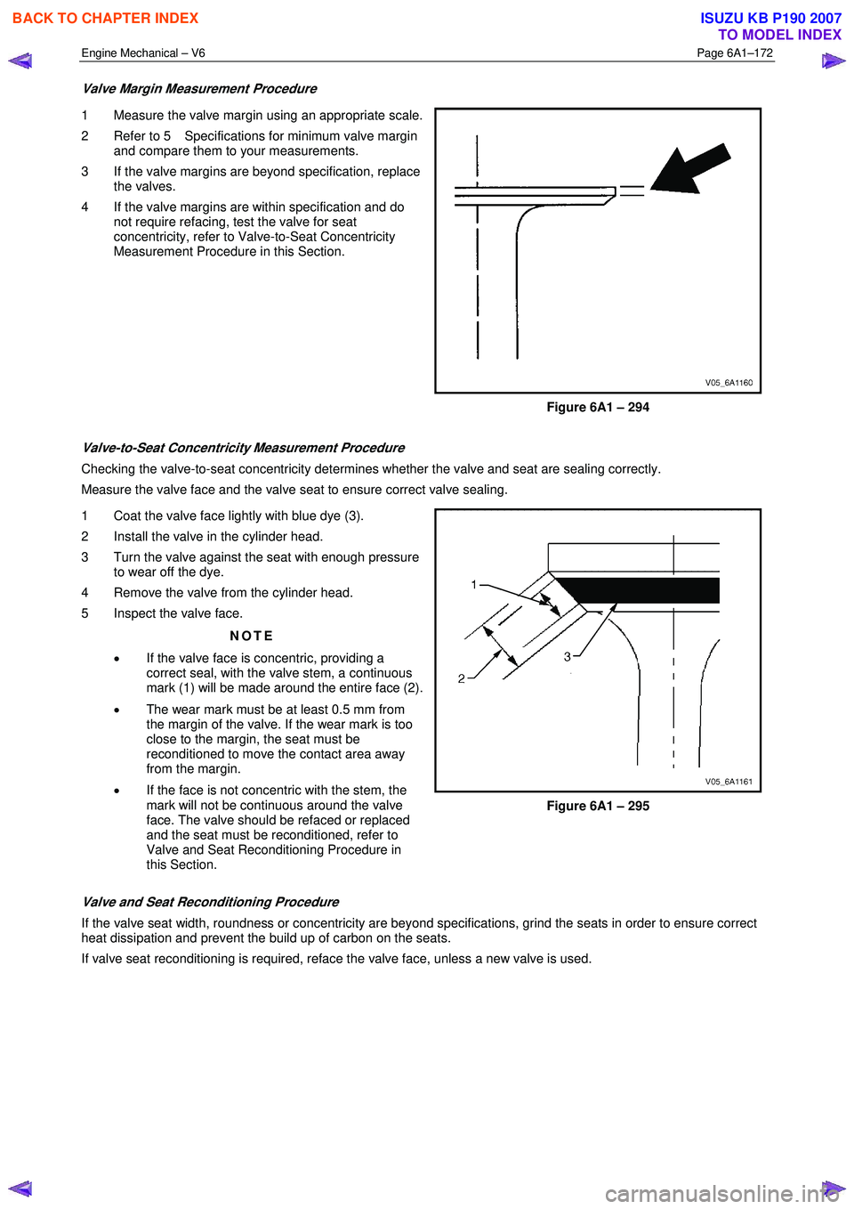
Valve Margin Measurement Procedure
1 Measure the valve margin using an appropriate scale.
2 Refer to 5 Specifications for minimum valve margin and compare them to your measurements.
3 If the valve margins are beyond specification, replace the valves.
4 If the valve margins are within specification and do not require refacing, test the valve for seat
concentricity, refer to Valve-to-Seat Concentricity
Measurement Procedure in this Section.
Figure 6A1 – 294
Valve-to-Seat Concentricity Measurement Procedure
Checking the valve-to-seat concentricity determines whether the valve and seat are sealing correctly.
Measure the valve face and the valve seat to ensure correct valve sealing.
1 Coat the valve face lightly with blue dye (3).
2 Install the valve in the cylinder head.
3 Turn the valve against the seat with enough pressure to wear off the dye.
4 Remove the valve from the cylinder head.
5 Inspect the valve face.
NOTE
• If the valve face is concentric, providing a
correct seal, with the valve stem, a continuous
mark (1) will be made around the entire face (2).
• The wear mark must be at least 0.5 mm from
the margin of the valve. If the wear mark is too
close to the margin, the seat must be
reconditioned to move the contact area away
from the margin.
• If the face is not concentric with the stem, the
mark will not be continuous around the valve
face. The valve should be refaced or replaced
and the seat must be reconditioned, refer to
Valve and Seat Reconditioning Procedure in
this Section.
Figure 6A1 – 295
Valve and Seat Reconditioning Procedure
If the valve seat width, roundness or concentricity are beyond specifications, grind the seats in order to ensure correct
heat dissipation and prevent the build up of carbon on the seats.
If valve seat reconditioning is required, reface the valve face, unless a new valve is used.
BACK TO CHAPTER INDEX
TO MODEL INDEX
ISUZU KB P190 2007
Page 2652 of 6020

Engine Mechanical – V6 Page 6A1–173
1 Grind the valve seats (2) to the correct angle
specification, refer to 5 Specifications.
2 Using the correct angle specification, grind and relieve the valve seats (1) to correctly position the
valve seating surface (2) to the valve.
3 Using the correct angle specification, grind and undercut the valve seats (3) to narrow the valve seat
widths to the specifications, refer to 5 Specifications.
4 If the original valve is being used, grind the valve to the specifications, refer to 5 Specifications.
Measure the valve margin again after grinding, refer
to Valve Margin Measurement Procedure in this
Section. Replace the valve if the margin is out of
specification. New valves do not require grinding.
5 W hen grinding the valves and seats, grind off as little material as possible. Cutting valve seat results in
lowering the valve spring pressure.
6 Install the valve in the cylinder head.
Figure 6A1 – 296
CAUTION
If using refaced valves, lap the valves into the
seats with a fine grinding compound. The
refacing and reseating operations should
leave the refinished surfaces smooth and true
so that minimal lapping is required. Excessive
lapping will groove the valve face and prevent
a good seat when hot.
NOTE
• Clean any remaining lapping compound from
the valve and seat with solvent and
compressed air prior to final assembly.
• If fitting new valves, do not lap the valves
under any condition.
7 After obtaining the correct valve seat width in the cylinder head, measure the valve stem height, refer to Valve Stem Height Measurement Procedure in this Section.
8 If the valve stem height is acceptable, test the seats for concentricity, refer to Valve-to-Seat Concentricity Measurement Procedure in this Section.
BACK TO CHAPTER INDEX
TO MODEL INDEX
ISUZU KB P190 2007
Page 2785 of 6020

Engine Mechanical – V6 Page 6A1–8
Page 6A1–8
1 General Information
The HFV6 engine features a closed vee, deep skirt die cast aluminium cylinder block with cast iron cylinder liners,
internally balanced crankcase, full length wa ter jackets and six bolt main bearing caps.
The cylinders are arranged in two banks of three with a 60 degree included angle between the two banks.
The right-hand bank of cylinders consists of number 1-3-5
cylinders and the left-hand bank of cylinders consists of
number 2-4-6.
The engine firing order is 1-2-3-4-5-6.
Each aluminium cylinder head is fitted with hardened valve
seats and four valves per cylinder: two intake and two
exhaust.
The valves are operated by two camshafts (DOHC) per
cylinder bank, one each for intake and exhaust valves.
The crankshaft is manufactured from forged steel. A reluctor
wheel is pressed in place onto the rear of the crankshaft for
the crankshaft position sensor.
The connecting rods are m anufactured from powdered
metal and the rod cap is separ ated during the manufacturing
process using the fractured me thod. This creates a stronger,
visually seamless rod to cap union.
Figure 6A1 – 1
MY06 Update
Throughout this Section, reference is made to 'MY06 Update' or 'Excluding MY06 Update'.
Vehicles manufactured post 14th Marc h 2007 are fitted with an updated version of the HFV6 engine. This engine
features a different timing chain, and as a result different sprocket teeth. This change also introduces the use of a new
special tool to assist in the serviceab ility of replacing the engine timing components.
All service procedures and descriptions specific to this update variation are qualified as 'MY06 Update'.
1.1 WARNING, CAUTION and NOTES
This Section contains various WARNING S, CAUTIONS and NOTE statements that y ou must observe carefully to reduce
the risk of death or injury during servic e, repair procedures or vehicle operation. Incorrect service or repair procedures
may damage the vehicle or cause operat ional faults. WARNINGS, CAUTION and NOTE statements are not exhaustive.
HOLDEN LTD can not possibly warn of a ll the potentially hazardous consequences of failure to follow these instructions.
Definition of WARNING, CAUTION and NOTE Statements
Diagnosis and repair procedures in this Section contain both general and specific WARNING, CAUTION and NOTE
statements. HOLDEN LTD is dedicated to the presentation of service information that helps the technician to diagnose
and repair the systems necessary for proper operation of the vehicle. Certain procedures may present a hazard to the
technician if they are not followed in the reco mmended manner. WARNING, CAUTION and NOTE statements are
designed to help prevent these hazards from o ccurring, but not all hazards can be foreseen.
WARNING defined
A WARNING statement immediately precedes an operating procedure or maint enance practice which, if not correctly
followed, could result in death or injury . A WARNING statement alerts you to ta ke necessary action or not to take a
prohibited action. If a WARNING statement is ignored, the following consequences may occur:
• Death or injury to the technician or other personnel working on the vehicle,
• Death or injury to other people in or near the workplace area, and / or
• Death or injury to the driver / or passenger(s) of the vehicle or other people, if the vehicle has been improperly
repaired.
CAUTION defined
A CAUTION statement immediately prec edes an operating procedure or maintenance practice which, if not correctly
followed, could result in damage to or destruction of equi pment, or corruption of data. If a CAUTION statement is
ignored, the following consequences may occur:
• Damage to the vehicle,
• Unnecessary vehicle repairs or component replacement,
BACK TO CHAPTER INDEX
TO MODEL INDEX
ISUZU KB P190 2007