air bleeding ISUZU KB P190 2007 Workshop Repair Manual
[x] Cancel search | Manufacturer: ISUZU, Model Year: 2007, Model line: KB P190, Model: ISUZU KB P190 2007Pages: 6020, PDF Size: 70.23 MB
Page 262 of 6020

POWER-ASSISTED STEERING SYSTEM 3B-1
SECTION 3B
POWER-ASSISTED STEERING SYSTEM
TABLE OF CONTENTS
PAGE
General Description......................................................................................................... 3B – 4
Power Steering System Test .......................................................................................... 3B – 7
Maintenance .................................................................................................................... . 3B – 8
Fluid Level .................................................................................................................... .... 3B – 8
Bleeding The Power Steering System ........................................................................... 3B – 8
Bleeding Procedure ......................................................................................................... 3B – 8
Flushing The Power Steering System............................................................................ 3B – 8
Steering Wheel Free Play Inspection ............................................................................. 3B – 9
Front End Alignment Inspection and Adjustment......................................................... 3B – 9
Special Tools .................................................................................................................. . 3B – 10
Power Steering Unit......................................................................................................... 3B – 11
Power Steering Unit and Associated Parts............................................................... 3B – 11
Removal ....................................................................................................................... 3B – 11
Installation ................................................................................................................... 3B – 12
Power Steering Unit Disassembled View.................................................................. 3B – 13
Disassembly ................................................................................................................ 3B – 14
Inspection and Repair................................................................................................. 3B – 14
Reassembly ................................................................................................................. 3B – 14
Main Data and Specifications .................................................................................... 3B – 15
Special Tools ............................................................................................................... 3B – 16
Power Steering Pump...................................................................................................... 3B – 17
Power Steering Pump and Associated Parts (4JH1-TC, 4JA1-T) ............................ 3B – 17
Removal ....................................................................................................................... 3B – 17
Installation ................................................................................................................... 3B – 17
Power Steering Pump Disassembled View .............................................................. 3B – 18
Disassembly ................................................................................................................ 3B – 19
Inspection and Repair................................................................................................. 3B – 19
Reassembly ................................................................................................................. 3B – 20
Main Data and Specifications .................................................................................... 3B – 20
BACK TO CHAPTER INDEX
TO MODEL INDEX
ISUZU KB P190 2007
Page 269 of 6020
3B-8 POWER-ASSISTED STEERING SYSTEM
6. Fully close the shutoff valve. Record the highest
pressures.
・ If the pressure recorded is within 9800-10300 kPa
(100-105 kg/cm
2/1422-1493psi), the pump is
functioning within its specifications.
・ If the pressure recorded is higher than 10300 kPa
(105 kg/cm
2/1493psi), the valve in the pump is
defective.
・ If the pressure recorded is lower than 9800 kPa
(100 kg/cm
2/1422psi), the valve or the rotating
assembly in the pump is defective.
7. If the pump pressures are within specifications, leave the valve open and turn (or have someone
else turn) the steering wheel fully in both directions.
Record the highest pressures and compare with the
maximum pump pressure recorded in step 6. If this
pressure cannot be built up at either side of the
power steering unit, the power steering unit is
leaking internally and must be replaced.
8. Shut the engine off, remove the testing gauge.
9. Reconnect the pressure hose, check the fluid level and make the needed repairs.
10. If the problem still exists, the steering and front suspension must be thoroughly examined.
Maintenance
The hydraulic system should be kept clean, the fluid
level in the reservoir should be checked at regula
r
intervals and fluid added when required. Refer to
Recommended Fluids and Lubricants in General
Information section for the type of fluid to be used and
the intervals for filling.
If the system contains some dirt, flush it as described in
this section. If it is exceptionally dirty, the pump must be
completely disassembled before further usage. (The
steering unit cannot be disassembled.)
All tubes, hoses, and fittings should be inspected for
leakage at regular intervals. Fittings must be tight. Make
sure the clips, clamps and supporting tubes and hoses
are in place and properly secured.
Power steering hoses and lines must not be twisted,
kinked or tightly bent. Air in the system will cause
spongy action and noisy operation. W hen a hose is
disconnected or when fluid is lost, for any reason, the
system must be bled after refilling. Refer to Bleeding the
Power Steering System in this section.
・ Inspect gear for looseness or damage.
・ Inspect hoses to insure they are not touching an
y
other parts of the vehicle.
・ Inspect fluid level and fill to the proper level.
Fluid Level
1. Run the engine until the power steering fluid
reaches normal operating temperature, about 55 °
C (130 °F), then shut the engine off.
2. Check the level of fluid in the reservoir.
3. If the fluid level is low, add power steering fluid as
specified in General Information to the proper level
and install the receiver cap.
4. W hen checking the fluid level after the steering system has been serviced, air must be bled from
the system. Refer to Bleeding the Power Steering
System in this section.
Bleeding the Power Steering System
W hen a power steering pump or unit has been installed,
or an oil line has been disconnected, the air that has
entered the system must be bled out before the vehicle
is operated. If air is allowed to remain in the powe
r
steering fluid system, noisy and unsatisfactory operation
of the system may result.
Bleeding Procedure
W hen bleeding the system, and any time fluid is added
to the power steering system, be sure to use only powe
r
steering fluid as specified in General Information.
1. Fill the pump fluid reservoir to the proper level and let the fluid settle for at least two minutes.
2. Start the engine and let it run for a few seconds. Do not turn the steering wheel. Then turn the engine
off.
3. Add fluid if necessary.
4. Repeat the above procedure until the fluid level remains constant after running the engine.
5. Raise and support the front end of the vehicle so that the wheels are off the ground.
6. Start the engine. Slowly turn the steering wheel right and left, lightly contacting the wheel stops.
7. Add power steering fluid if necessary.
8. Lower the vehicle, set the steering wheel at the straight forward position after turning it to its full
steer positions 2 or 3 times, and stop the engine.
9. Check the fluid level and refill as required.
10. If the fluid is extremely foamy, allow the vehicle to settle for a few minutes, then repeat the above
procedure.
Flushing the Power Steering System
1. Raise and support the front end of the vehicle off
the ground until the wheels are free to turn.
2. Remove the fluid return line at the pump inlet connector and plug the connector port on the pump.
Direct the line toward a large container to catch the
draining fluid.
3. W hile running the engine at idle, fill the reservoi
r
with new power steering fluid. Turn the steering
wheel in both directions. Do not contact or hold the
steering wheel to the wheel stops. This will cause
the pump to go to pressure relief mode, which ma
y
cause a sudden fluid overflow at the reservoir.
BACK TO CHAPTER INDEX
TO MODEL INDEX
ISUZU KB P190 2007
Page 620 of 6020
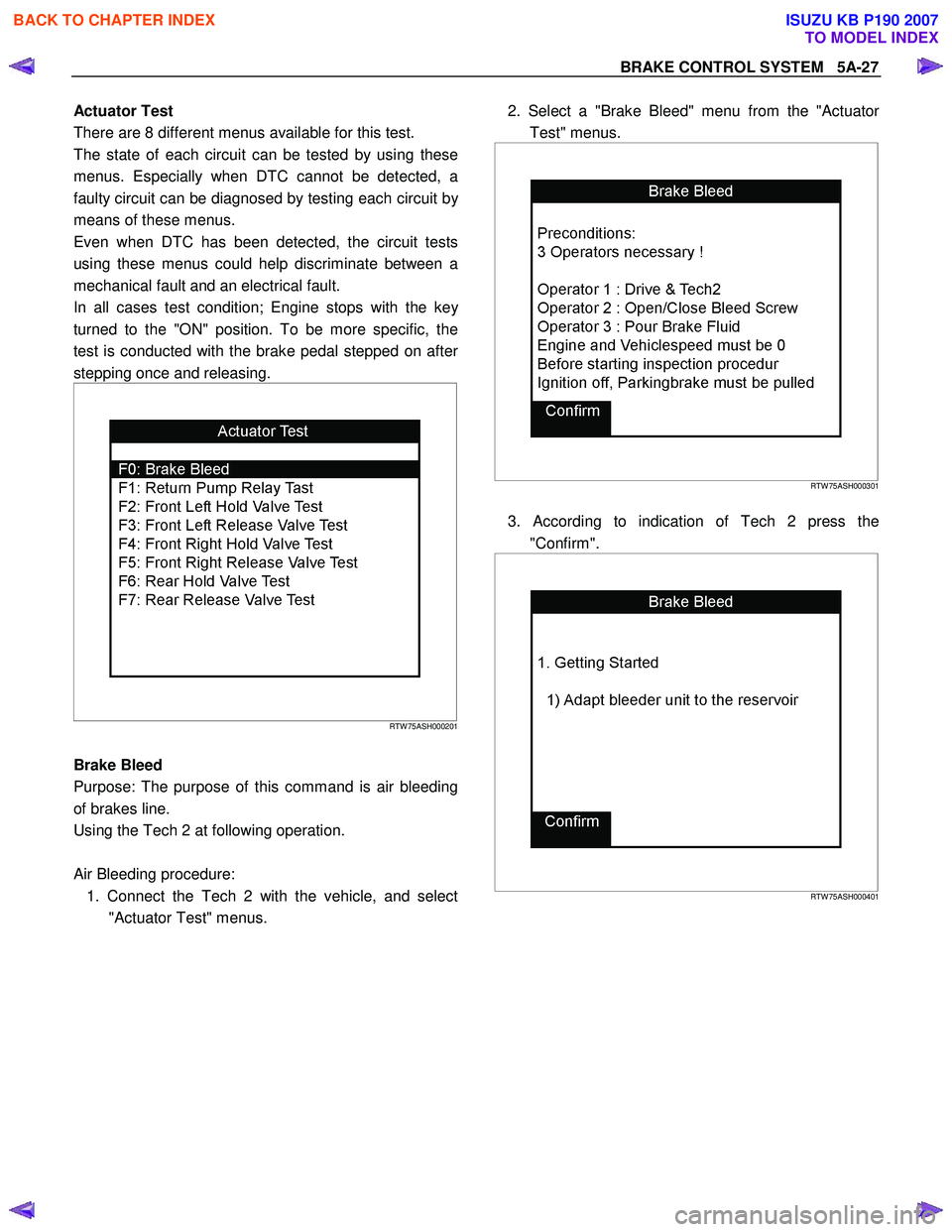
BRAKE CONTROL SYSTEM 5A-27
Actuator Test
There are 8 different menus available for this test.
The state of each circuit can be tested by using these
menus. Especially when DTC cannot be detected, a
faulty circuit can be diagnosed by testing each circuit b
y
means of these menus.
Even when DTC has been detected, the circuit tests
using these menus could help discriminate between a
mechanical fault and an electrical fault.
In all cases test condition; Engine stops with the ke
y
turned to the "ON" position. To be more specific, the
test is conducted with the brake pedal stepped on afte
r
stepping once and releasing.
RTW 75ASH000201
Brake Bleed
Purpose: The purpose of this command is air bleeding
of brakes line.
Using the Tech 2 at following operation.
Air Bleeding procedure: 1. Connect the Tech 2 with the vehicle, and select "Actuator Test" menus.
2. Select a "Brake Bleed" menu from the "Actuato
r
Test" menus.
RTW 75ASH000301
3. According to indication of Tech 2 press the
"Confirm".
RTW 75ASH000401
BACK TO CHAPTER INDEX
TO MODEL INDEX
ISUZU KB P190 2007
Page 724 of 6020
BRAKES 5C-25
Filling Master Cylinder Reservoir
CAUTION:
Use only specified brake fluid. Do not use any fluid which
contains a petroleum base. Do not use a container which
has been used for petroleum based fluids or a containe
r
which is wet with water. Petroleum based fluid will cause
swelling and distortion of rubber parts in the hydraulic
brake system. Water mixed with brake fluid lowers the
fluid boiling point. Keep all fluid containers capped to
prevent contamination.
Always fill the master cylinder reservoir when the engine
is cold.
Never allow the brake fluid to come in contact with the
painted surfaces.
The master cylinder reservoir must be kept properly filled
to ensure adequate reserve and to prevent air and
moisture from entering the hydraulic system. However,
because of expansion due to heat absorbed from the
brakes and the engine, the reservoir must not be
overfilled. Thoroughly clean reservoir cap before removal
to avoid getting dirt into reservoir. Add fluid as required to
bring level to the “MAX” mark on the reservoir tank. Use
“DOT 3” Hydraulic Brake Fluid.
Leakage of Brake Fluid
W ith engine idling, set shift lever in the neutral position and
continue to depress brake pedal at a constant pedal
application force.
Should the pedal stroke become deeper gradually, leakage
from the hydraulic pressure system is possible.
Make sure by visual check that there is no leak.
BLEEDING OF THE BRAKE HYDRAULIC
CIRCUIT
If air enters the bake lines, it will cause poor brake action.
Therefore, bleeding should be performed if the brakes have
been used with the level of brake fluid in the reservoi
r
excessively low or if brake pipes have been disconnected in
the course of brake servicing.
The bleeding operation calls for co-operative action of 2
persons.
• Set the parking brake firmly while bleeding.
• Perform bleeding operation with ENGINE RUNNING, to
prevent damage to push rod seal.
Make sure exhaust is suitably ventilated.
• Bleed the hydraulic system with the fluid reservoir filled to
the specified level.
• Bleed the system starting with the rear wheel cylinde
r
farthest from the master cylinder.
BACK TO CHAPTER INDEX
TO MODEL INDEX
ISUZU KB P190 2007
Page 725 of 6020
5C-26 BRAKES
A bleeding operation is necessary to remove air from the
hydraulic brake system whenever air is introduced into the
hydraulic system. It may be necessary to bleed the hydraulic
system at all four brakes if air has been introduced through a
low fluid level or by disconnecting brake pipes at the maste
r
cylinder. If a brake pipe is disconnected at one wheel, only that
wheel cylinder/caliper needs to be bled. If the pipes are
disconnected at any fitting located between the master cylinde
r
and brakes, then the brake system served by the disconnected
pipe must be bled.
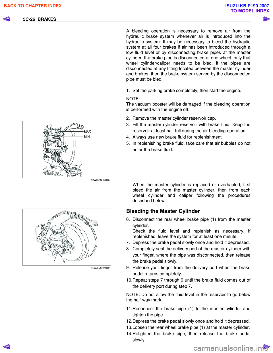
1. Set the parking brake completely, then start the engine.
NOTE:
The vacuum booster will be damaged if the bleeding operation
is performed with the engine off.
2. Remove the master cylinder reservoir cap.
RTW 75CSH001701
3. Fill the master cylinder reservoir with brake fluid. Keep the
reservoir at least half full during the air bleeding operation.
4. Always use new brake fluid for replenishment.
5. In replenishing brake fluid, take care that air bubbles do not enter the brake fluid.
W hen the master cylinder is replaced or overhauled, first
bleed the air from the master cylinder, then from each
wheel cylinder and caliper following the procedures
described below.
RTW 75CSH001801
Bleeding the Master Cylinder
6. Disconnect the rear wheel brake pipe (1) from the master
cylinder.
Check the fluid level and replenish as necessary. I
f
replenished, leave the system for at least one minute.
7. Depress the brake pedal slowly once and hold it depressed.
8. Completely seal the delivery port of the master cylinder with your finger, where the pipe was disconnected, then release
the brake pedal slowly.
9. Release your finger from the delivery port when the brake pedal returns completely.
10. Repeat steps 7 through 9 until the brake fluid comes out o
f
the delivery port during step 7.
NOTE: Do not allow the fluid level in the reservoir to go belo
w
the half-way mark.
11. Reconnect the brake pipe (1) to the master cylinder and tighten the pipe.
12. Depress the brake pedal slowly once and hold it depressed.
13. Loosen the rear wheel brake pipe (1) at the master cylinder.
14. Retighten the brake pipe, then release the brake pedal slowly.
BACK TO CHAPTER INDEX
TO MODEL INDEX
ISUZU KB P190 2007
Page 726 of 6020
BRAKES 5C-27
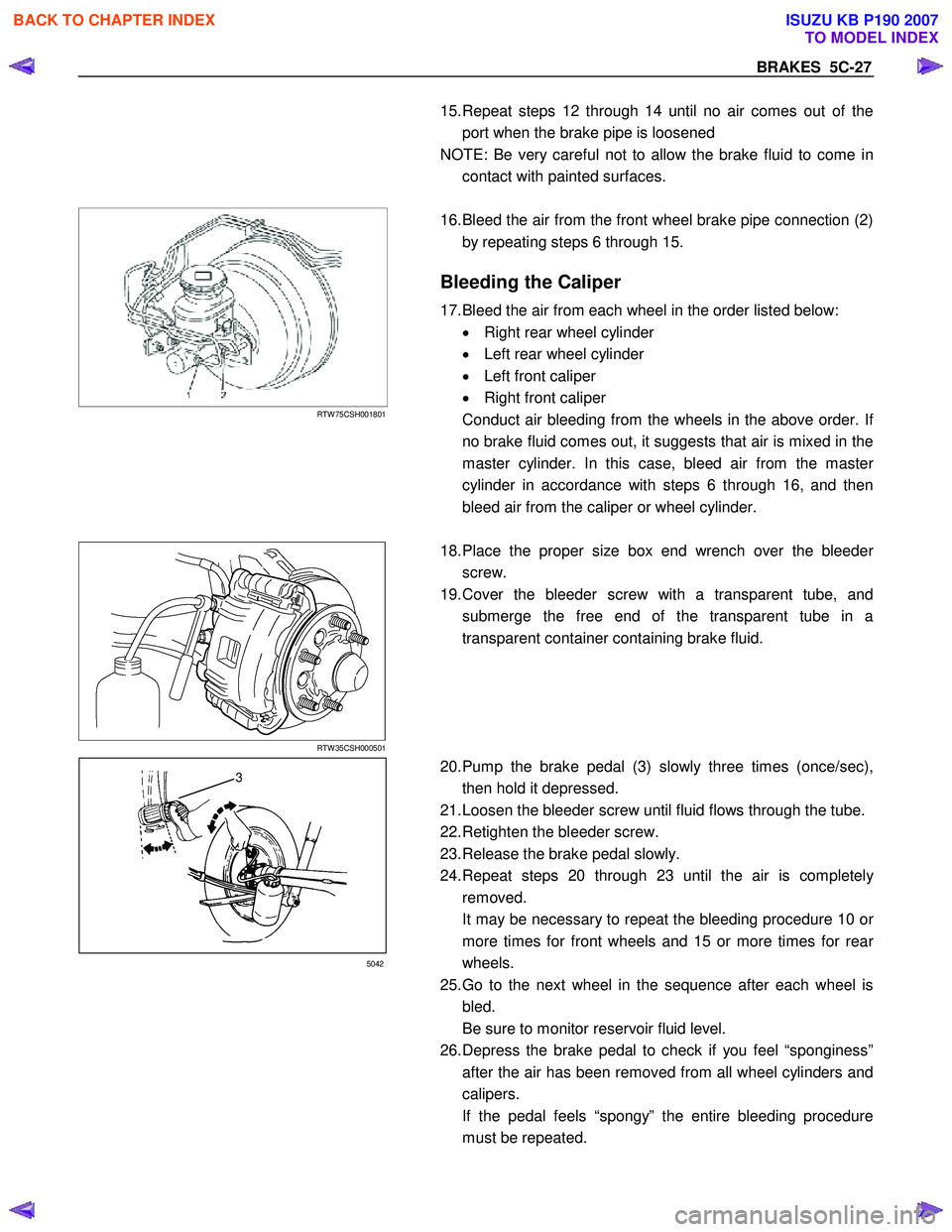
15. Repeat steps 12 through 14 until no air comes out of the
port when the brake pipe is loosened
NOTE: Be very careful not to allow the brake fluid to come in contact with painted surfaces.
RTW 75CSH001801
16. Bleed the air from the front wheel brake pipe connection (2)
by repeating steps 6 through 15.
Bleeding the Caliper
17. Bleed the air from each wheel in the order listed below: • Right rear wheel cylinder
• Left rear wheel cylinder
• Left front caliper
• Right front caliper
Conduct air bleeding from the wheels in the above order. I
f
no brake fluid comes out, it suggests that air is mixed in the
master cylinder. In this case, bleed air from the maste
r
cylinder in accordance with steps 6 through 16, and then
bleed air from the caliper or wheel cylinder.
RTW 35CSH000501
18. Place the proper size box end wrench over the bleeder
screw.
19. Cover the bleeder screw with a transparent tube, and submerge the free end of the transparent tube in a
transparent container containing brake fluid.
3
5042
20. Pump the brake pedal (3) slowly three times (once/sec),
then hold it depressed.
21. Loosen the bleeder screw until fluid flows through the tube.
22. Retighten the bleeder screw.
23. Release the brake pedal slowly.
24. Repeat steps 20 through 23 until the air is completel
y
removed.
It may be necessary to repeat the bleeding procedure 10 o
r
more times for front wheels and 15 or more times for rear
wheels.
25. Go to the next wheel in the sequence after each wheel is bled.
Be sure to monitor reservoir fluid level.
26. Depress the brake pedal to check if you feel “sponginess” after the air has been removed from all wheel cylinders and
calipers.
If the pedal feels “spongy” the entire bleeding procedure must be repeated.
BACK TO CHAPTER INDEX
TO MODEL INDEX
ISUZU KB P190 2007
Page 727 of 6020
5C-28 BRAKES
27. After the bleeding operation is completed on each individual
wheel, check the level of the brake fluid in the reservoir and
replenish up to the “MAX" level as necessary.
28. Attach the reservoir cap.
29. Stop the engine.
05007-1
BRAKE LINE (HOSES AND PIPES)
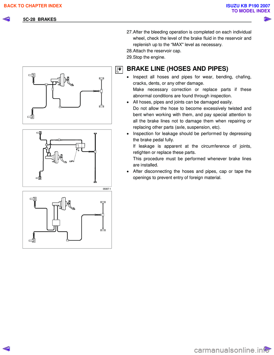
• Inspect all hoses and pipes for wear, bending, chafing,
cracks, dents, or any other damage.
Make necessary correction or replace parts if these abnormal conditions are found through inspection.
• All hoses, pipes and joints can be damaged easily.
Do not allow the hose to become excessively twisted and bent when working with them, and pay special attention to
all the brake lines not to damage them when repairing o
r
replacing other parts (axle, suspension, etc).
• Inspection for leakage should be performed by depressing
the brake pedal fully.
If leakage is apparent at the circumference of joints, retighten or replace these parts.
This procedure must be performed whenever brake lines are installed.
• After disconnecting the hoses and pipes, cap or tape the
openings to prevent entry of foreign material.
BACK TO CHAPTER INDEX
TO MODEL INDEX
ISUZU KB P190 2007
Page 831 of 6020
6A – 26 ENGINE MECHANICAL
041RY00011
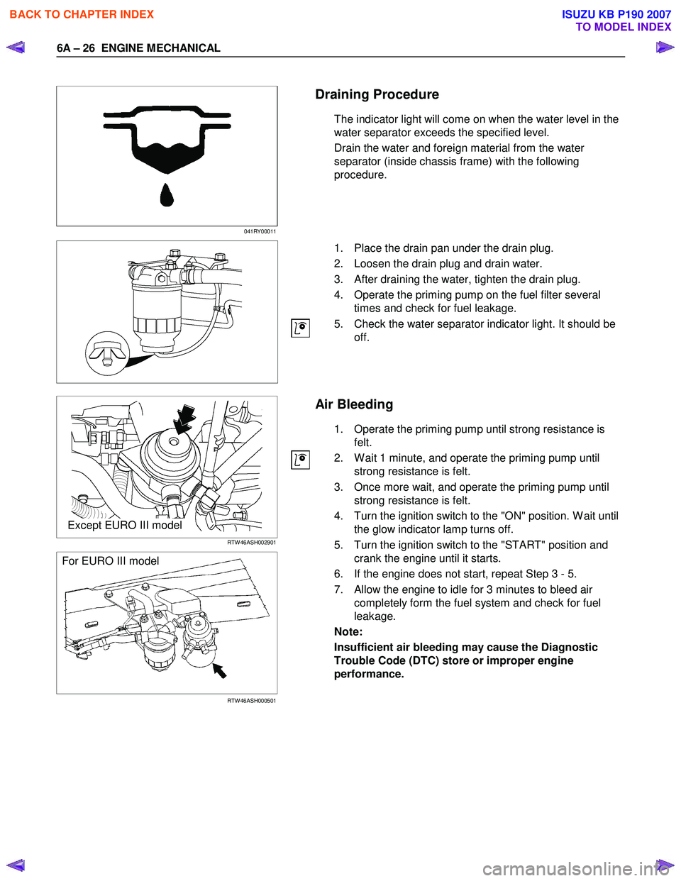
Draining Procedure
The indicator light will come on when the water level in the
water separator exceeds the specified level.
Drain the water and foreign material from the water
separator (inside chassis frame) with the following
procedure.
1. Place the drain pan under the drain plug.
2. Loosen the drain plug and drain water.
3. After draining the water, tighten the drain plug.
4. Operate the priming pump on the fuel filter several times and check for fuel leakage.
5. Check the water separator indicator light. It should be off.
Except EURO III model
RTW 46ASH002901
For EURO III model
RTW 46ASH000501
Air Bleeding
1. Operate the priming pump until strong resistance is felt.
2. W ait 1 minute, and operate the priming pump until strong resistance is felt.
3. Once more wait, and operate the priming pump until strong resistance is felt.
4. Turn the ignition switch to the "ON" position. W ait until the glow indicator lamp turns off.
5. Turn the ignition switch to the "START" position and crank the engine until it starts.
6. If the engine does not start, repeat Step 3 - 5.
7. Allow the engine to idle for 3 minutes to bleed air completely form the fuel system and check for fuel
leakage.
Note:
Insufficient air bleeding may cause the Diagnostic
Trouble Code (DTC) store or improper engine
performance.
BACK TO CHAPTER INDEX
TO MODEL INDEX
ISUZU KB P190 2007
Page 968 of 6020
6C – 4 FUEL SYSTEM
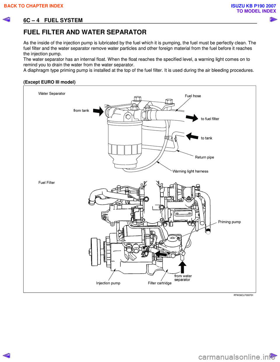
FUEL FILTER AND WATER SEPARATOR
As the inside of the injection pump is lubricated by the fuel which it is pumping, the fuel must be perfectly clean. The
fuel filter and the water separator remove water particles and other foreign material from the fuel before it reaches
the injection pump.
The water separator has an internal float. W hen the float reaches the specified level, a warning light comes on to
remind you to drain the water from the water separator.
A diaphragm type priming pump is installed at the top of the fuel filter. It is used during the air bleeding procedures.
(Except EURO III model)
RTW 36CLF000701
BACK TO CHAPTER INDEX
TO MODEL INDEX
ISUZU KB P190 2007
Page 1137 of 6020
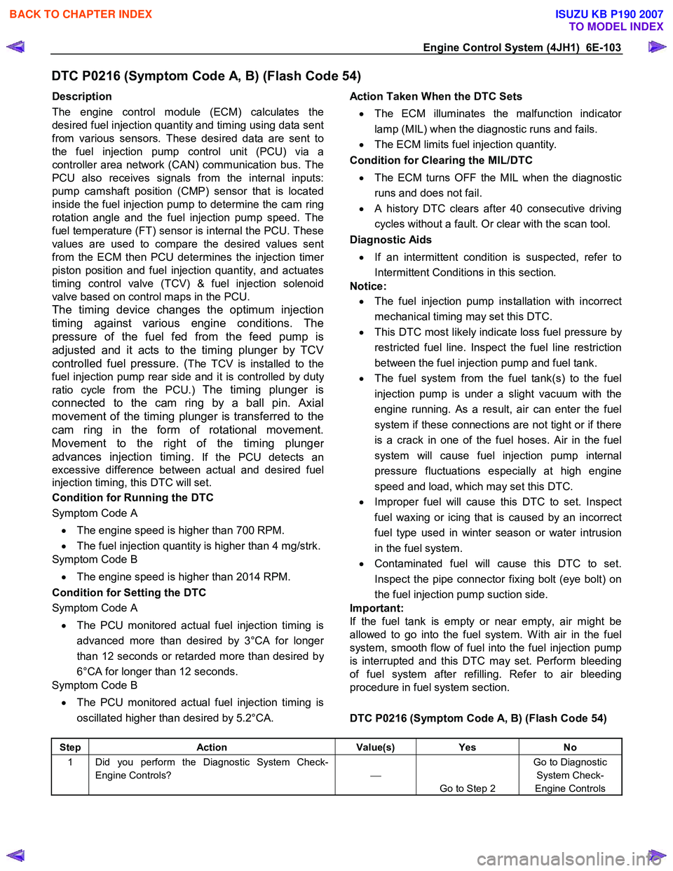
Engine Control System (4JH1) 6E-103
DTC P0216 (Symptom Code A, B) (Flash Code 54)
Description
The engine control module (ECM) calculates the
desired fuel injection quantity and timing using data sent
from various sensors. These desired data are sent to
the fuel injection pump control unit (PCU) via a
controller area network (CAN) communication bus. The
PCU also receives signals from the internal inputs:
pump camshaft position (CMP) sensor that is located
inside the fuel injection pump to determine the cam ring
rotation angle and the fuel injection pump speed. The
fuel temperature (FT) sensor is internal the PCU. These
values are used to compare the desired values sent
from the ECM then PCU determines the injection time
r
piston position and fuel injection quantity, and actuates
timing control valve (TCV) & fuel injection solenoid
valve based on control maps in the PCU.
The timing device changes the optimum injection
timing against various engine conditions. The
pressure of the fuel fed from the feed pump is
adjusted and it acts to the timing plunger by TCV
controlled fuel pressure. (
The TCV is installed to the
fuel injection pump rear side and it is controlled by dut
y
ratio cycle from the PCU.) The timing plunger is
connected to the cam ring by a ball pin. Axial
movement of the timing plunger is transferred to the
cam ring in the form of rotational movement.
Movement to the right of the timing plunge
r
advances injection timing.
If the PCU detects an
excessive difference between actual and desired fuel
injection timing, this DTC will set.
Condition for Running the DTC
Symptom Code A
• The engine speed is higher than 700 RPM.
• The fuel injection quantity is higher than 4 mg/strk.
Symptom Code B
• The engine speed is higher than 2014 RPM.
Condition for Setting the DTC
Symptom Code A
• The PCU monitored actual fuel injection timing is
advanced more than desired by 3°CA for longe
r
than 12 seconds or retarded more than desired by
6°CA for longer than 12 seconds.
Symptom Code B
• The PCU monitored actual fuel injection timing is
oscillated higher than desired by 5.2°CA.
Action Taken When the DTC Sets
• The ECM illuminates the malfunction indicato
r
lamp (MIL) when the diagnostic runs and fails.
• The ECM limits fuel injection quantity.
Condition for Clearing the MIL/DTC
• The ECM turns OFF the MIL when the diagnostic
runs and does not fail.
• A history DTC clears after 40 consecutive driving
cycles without a fault. Or clear with the scan tool.
Diagnostic Aids
• If an intermittent condition is suspected, refer to
Intermittent Conditions in this section.
Notice:
• The fuel injection pump installation with incorrect
mechanical timing may set this DTC.
• This DTC most likely indicate loss fuel pressure by
restricted fuel line. Inspect the fuel line restriction
between the fuel injection pump and fuel tank.
• The fuel system from the fuel tank(s) to the fuel
injection pump is under a slight vacuum with the
engine running. As a result, air can enter the fuel
system if these connections are not tight or if there
is a crack in one of the fuel hoses. Air in the fuel
system will cause fuel injection pump internal
pressure fluctuations especially at high engine
speed and load, which may set this DTC.
• Improper fuel will cause this DTC to set. Inspect
fuel waxing or icing that is caused by an incorrect
fuel type used in winter season or water intrusion
in the fuel system.
• Contaminated fuel will cause this DTC to set.
Inspect the pipe connector fixing bolt (eye bolt) on
the fuel injection pump suction side.
Important:
If the fuel tank is empty or near empty, air might be
allowed to go into the fuel system. W ith air in the fuel
system, smooth flow of fuel into the fuel injection pump
is interrupted and this DTC may set. Perform bleeding
of fuel system after refilling. Refer to air bleeding
procedure in fuel system section.
DTC P0216 (Symptom Code A, B) (Flash Code 54)
Step Action Value(s) Yes No
1 Did you perform the Diagnostic System Check-
Engine Controls?
Go to Step 2 Go to Diagnostic
System Check-
Engine Controls
BACK TO CHAPTER INDEX
TO MODEL INDEX
ISUZU KB P190 2007