fuse diagram ISUZU KB P190 2007 Workshop Repair Manual
[x] Cancel search | Manufacturer: ISUZU, Model Year: 2007, Model line: KB P190, Model: ISUZU KB P190 2007Pages: 6020, PDF Size: 70.23 MB
Page 1034 of 6020
ENGINE ELECTRICAL 6D – 33
PRE-HEATING SYSTEM
INSPECTION AND REPAIR
Make the necessary adjustments, repairs, and part replacement if excessive wear of damage is discovered during
inspection.
VISUAL CHECK
Check the main fuses and glow indicator for damage.
Replace the part(s) if required.
GLOW RELAY
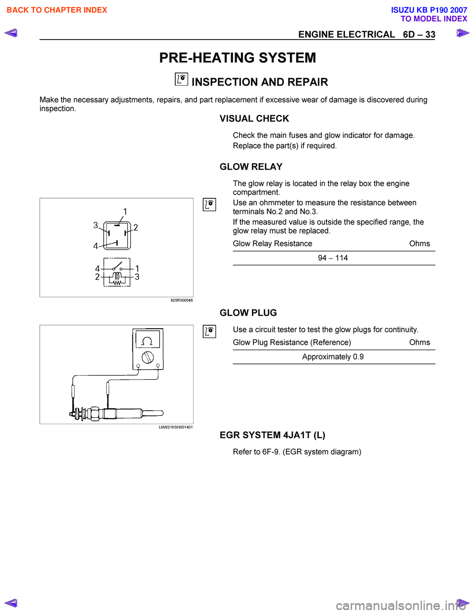
The glow relay is located in the relay box the engine
compartment.
825R300046
Use an ohmmeter to measure the resistance between
terminals No.2 and No.3.
If the measured value is outside the specified range, the
glow relay must be replaced.
Glow Relay Resistance Ohms
94 − 114
GLOW PLUG
LNW21KSH001401
Use a circuit tester to test the glow plugs for continuity.
Glow Plug Resistance (Reference) Ohms
Approximately 0.9
EGR SYSTEM 4JA1T (L)
Refer to 6F-9. (EGR system diagram)
BACK TO CHAPTER INDEX
TO MODEL INDEX
ISUZU KB P190 2007
Page 2171 of 6020
SECTION 6E
TABLE OF CONTENTS
C24SE ENGINE DRIVEABILITY AND EMISSIONS
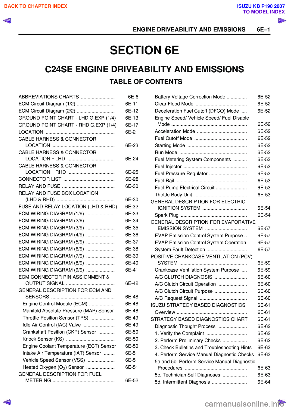
ABBREVIATIONS CHARTS ......................... 6E-6
ECM Circuit Diagram (1/2) ............................ 6E-11
ECM Circuit Diagram (2/2) ............................ 6E-12
GROUND POINT CHART - LHD G.EXP (1/4) 6E-13
GROUND POINT CHART - RHD G.EXP (1/4) 6E-17
LOCATION ................................................... 6E-21
CABLE HARNESS & CONNECTOR LOCATION .............................................. 6E-23
CABLE HARNESS & CONNECTOR LOCATION - LHD ................................... 6E-24
CABLE HARNESS & CONNECTOR LOCATION - RHD ................................... 6E-25
CONNECTOR LIST ...................................... 6E-28
RELAY AND FUSE ....................................... 6E-30
RELAY AND FUSE BOX LOCATION (LHD & RHD) ........................................... 6E-30
FUSE AND RELAY LOCATION (LHD & RHD) 6E-32
ECM WIRING DIAGRAM (1/9) ..................... 6E-33
ECM WIRING DIAGRAM (2/9) ..................... 6E-34
ECM WIRING DIAGRAM (3/9) ..................... 6E-35
ECM WIRING DIAGRAM (4/9) ..................... 6E-36
ECM WIRING DIAGRAM (5/9) ..................... 6E-37
ECM WIRING DIAGRAM (6/9) ..................... 6E-38
ECM WIRING DIAGRAM (7/9) ..................... 6E-39
ECM WIRING DIAGRAM (8/9) ..................... 6E-40
ECM WIRING DIAGRAM (9/9) ..................... 6E-41
ECM CONNECTOR PIN ASSIGNMENT & OUTPUT SIGNAL .................................... 6E-42
GENERAL DESCRIPTION FOR ECM AND SENSORS ............................................... 6E-48
Engine Control Module (ECM) ................... 6E-48
Manifold Absolute Pressure (MAP) Sensor 6E-48
Throttle Position Sensor (TPS) .................. 6E-49
Idle Air Control (IAC) Valve ....................... 6E-49
Crankshaft Position (CKP) Sensor ............ 6E-50
Knock Sensor (KS) .................................... 6E-50
Engine Coolant Temperature (ECT) Sensor 6E-50
Intake Air Temperature (IAT) Sensor ........ 6E-51
Vehicle Speed Sensor (VSS) .................... 6E-51
Heated Oxygen (O
2) Sensor ..................... 6E-51
GENERAL DESCRIPTION FOR FUEL METERING .............................................. 6E-52 Battery Voltage Correction Mode ............... 6E-52
Clear Flood Mode ...................................... 6E-52
Deceleration Fuel Cutoff (DFCO) Mode .... 6E-52
Engine Speed/ Vehicle Speed/ Fuel Disable Mode ........................................................ 6E-52
Acceleration Mode ..................................... 6E-52
Fuel Cutoff Mode ....................................... 6E-52
Starting Mode ............................................ 6E-52
Run Mode .................................................. 6E-52
Fuel Metering System Components .......... 6E-53
Fuel Injector ............................................... 6E-53
Fuel Pressure Regulator ............................ 6E-53
Fuel Rail ..................................................... 6E-53
Fuel Pump Electrical Circuit ....................... 6E-53
Thottle Body Unit ....................................... 6E-53
GENERAL DESCRIPTION FOR ELECTRIC IGNITION SYSTEM ................................. 6E-54
Spark Plug ................................................. 6E-54
GENERAL DESCRIPTION FOR EVAPORATIVE EMISSION SYSTEM ............................... 6E-57
EVAP Emission Control System Purpose .. 6E-57
EVAP Emission Control System Operation 6E-57
System Fault Detection .............................. 6E-57
POSITIVE CRANKCASE VENTILATION (PCV) SYSTEM .................................................. 6E-59
Crankcase Ventilation System Purpose .... 6E-59
A/C CLUTCH DIAGNOSIS ........................ 6E-60
A/C Clutch Circuit Operation ...................... 6E-60
A/C Clutch Circuit Purpose ........................ 6E-60
A/C Request Signal ................................... 6E-60
ISUZU STRATEGY BASED DIAGNOSTICS 6E-61
Overview .................................................... 6E-61
STRATEGY BASED DIAGNOSTICS CHART 6E-61 Diagnostic Thought Process ...................... 6E-62
1. Verify the Complaint .............................. 6E-62
2. Perform Preliminary Checks .................. 6E-62
3. Check Bulletins and Troubleshooting Hints 6E-63
4. Perform Service Manual Diagnostic Checks 6E-63
5a and 5b. Perform Service Manual Diagnostic Procedures .............................................. 6E-63
5c. Technician Self Diagnoses .................. 6E-63
5d. Intermittent Diagnosis .......................... 6E-64
6 E –1
E N GINE DRIV EABILITY AND E M IS SIONS
BACK TO CHAPTER INDEX
TO MODEL INDEX
ISUZU KB P190 2007
Page 2233 of 6020
ENGINE DRIVEABILITY AND EMISSIONS 6E–63
3. Check Bulletins and Troubleshooting Hints
NOTE: As estimated 30 percent of successful vehicle
repairs are diagnosed with this step!
What you should do
You should have enough information gained from
preliminary checks to accurately search for a bulletin
and other related service information. Some service
manual sections provide troubleshooting hints that
match symptoms with specific complaints.
What resources you should use
You should use the following resources for assistance in
checking for bulletins and troubleshooting hints:
• Printed bulletins
• Access ISUZU Bulletin Web site.
• Videotapes
• Service manual
4. Perform Service Manual Diagnostic Checks
What you should do
The “System Checks” in most service manual sections
and in most cells of section 8A (electrical) provide you
with:
• A systematic approach to narrowing down the possible causes of a system fault
• Direction to specific diagnostic procedures in the service manual
• Assistance to identify what systems work correctly
What resources you should use
Whenever possible, you should use the following
resources to perform service manual checks:
• Service manual
• Technical equipment (for viewing DTCs and analyzing data)
• Digital multimeter and circuit testing tools
• Other tools as needed
5a and 5b. Perform Service Manual Diagnostic Procedures
NOTE: An estimated 40 percent of successful vehicle
repairs are diagnosed with these steps!
What you should do
When directed by service manual diagnostic checks,
you must then carefully and accurately perform the
steps of diagnostic procedures to locate the fault related to the customer complaint.
What resources you should use
Whenever appropriate, you should use the following
resources to perform service manual diagnostic
procedures:
• Service manual
• Technical equipment (for analyzing diagnostic data)
• Digital multimeter and circuit testing tools
• Essential and special tools
5c. Technician Self Diagnoses
When there is no DTC stored and no matching
symptom for the condition identified in the service
manual, you must begin with a thorough understanding
of how the system(s) operates. Efficient use of the
service manual combined with you experience and a
good process of elimination will result in accurate
diagnosis of the condition.
What you should do
Step 1: Identify and understand the suspect
circuit(s)
Having completed steps 1 through 4 of the Strategy
Based Diagnostics chart, you should have enough
information to identify the system(s) or sub-system(s)
involved. Using the service manual, you should
determine and investigate the following circuit
characteristics:
• Electrical: – How is the circuit powered (power distributioncharts and/or fuse block details)?
– How is the circuit grounded (ground distribution charts)?
– How is the circuit controlled or sensed (theory of operation):
– If it is a switched circuit, is it normally open or normally closed?
– Is the power switched or is the ground switched?
– Is it a variable resistance circuit (ECT sensor or TP sensor, for example)?
– Is it a signal generating device (MAF sensor of VSS, for example)?
– Does it rely on some mechanical/vacuum device to operate?
•Physical:
– Where are the circuit components (componentlocators and wire harness routing diagrams):
– Are there areas where wires could be chafed or pinched (brackets or frames)?
– Are there areas subjected to extreme temperatures?
BACK TO CHAPTER INDEX
TO MODEL INDEX
ISUZU KB P190 2007
Page 3326 of 6020
Engine Management – V6 – Diagnostics Page 6C1-2–48
Additional Information
• Use the J 35616-B Connector Test Adapter Kit for any test that requires probing the ECM harness connector or a
component harness connector.
• Inspect the ignition coils for aftermarket devices. An aftermarket device connected to the ignition coil circuits, may
cause a condition with the ignition coils.
• For an intermittent fault condition, refer to 5.2 Intermittent Fault Conditions in this Section.
• To assist diagnosis, refer to 3 W iring Diagrams and Connector Charts in this Section, for the system wiring
diagram and connector charts.
Test Description
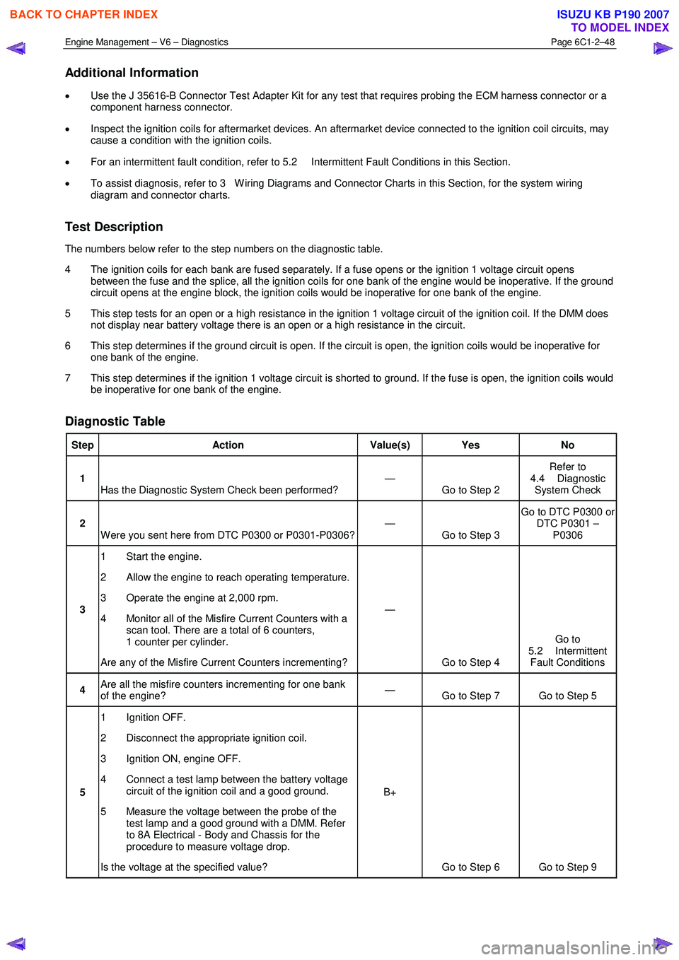
The numbers below refer to the step numbers on the diagnostic table.
4 The ignition coils for each bank are fused separately. If a fuse opens or the ignition 1 voltage circuit opens between the fuse and the splice, all the ignition coils for one bank of the engine would be inoperative. If the ground
circuit opens at the engine block, the ignition coils would be inoperative for one bank of the engine.
5 This step tests for an open or a high resistance in the ignition 1 voltage circuit of the ignition coil. If the DMM does not display near battery voltage there is an open or a high resistance in the circuit.
6 This step determines if the ground circuit is open. If the circuit is open, the ignition coils would be inoperative for one bank of the engine.
7 This step determines if the ignition 1 voltage circuit is shorted to ground. If the fuse is open, the ignition coils would be inoperative for one bank of the engine.
Diagnostic Table
Step Action Value(s) Yes No
1
Has the Diagnostic System Check been performed? —
Go to Step 2 Refer to
4.4 Diagnostic System Check
2 W ere you sent here from DTC P0300 or P0301-P0306? —
Go to Step 3 Go to DTC P0300 or
DTC P0301 – P0306
3 1 Start the engine.
2 Allow the engine to reach operating temperature.
3 Operate the engine at 2,000 rpm.
4 Monitor all of the Misfire Current Counters with a scan tool. There are a total of 6 counters,
1 counter per cylinder.
Are any of the Misfire Current Counters incrementing? —
Go to Step 4 Go to
5.2 Intermittent Fault Conditions
4 Are all the misfire counters incrementing for one bank
of the engine? —
Go to Step 7 Go to Step 5
5 1 Ignition OFF.
2 Disconnect the appropriate ignition coil.
3 Ignition ON, engine OFF.
4 Connect a test lamp between the battery voltage circuit of the ignition coil and a good ground.
5 Measure the voltage between the probe of the test lamp and a good ground with a DMM. Refer
to 8A Electrical - Body and Chassis for the
procedure to measure voltage drop.
Is the voltage at the specified value? B+
Go to Step 6 Go to Step 9
BACK TO CHAPTER INDEX
TO MODEL INDEX
ISUZU KB P190 2007
Page 3342 of 6020
Engine Management – V6 – Diagnostics Page 6C1-2–64
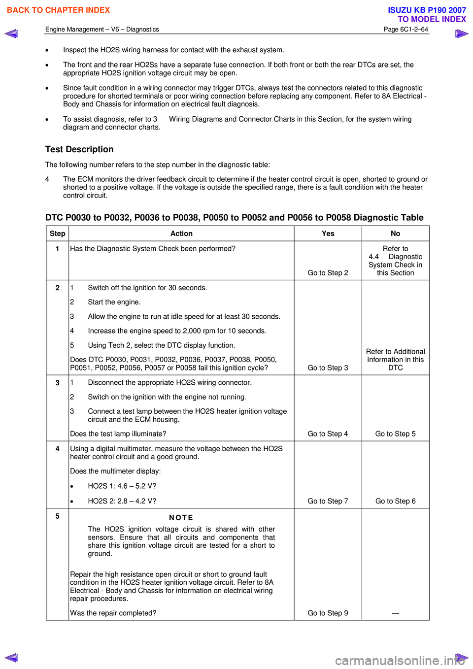
• Inspect the HO2S wiring harness for contact with the exhaust system.
• The front and the rear HO2Ss have a separate fuse connection. If both front or both the rear DTCs are set, the
appropriate HO2S ignition voltage circuit may be open.
• Since fault condition in a wiring connector may trigger DTCs, always test the connectors related to this diagnostic
procedure for shorted terminals or poor wiring connection before replacing any component. Refer to 8A Electrical -
Body and Chassis for information on electrical fault diagnosis.
• To assist diagnosis, refer to 3 W iring Diagrams and Connector Charts in this Section, for the system wiring
diagram and connector charts.
Test Description
The following number refers to the step number in the diagnostic table:
4 The ECM monitors the driver feedback circuit to determine if the heater control circuit is open, shorted to ground or shorted to a positive voltage. If the voltage is outside the specified range, there is a fault condition with the heater
control circuit.
DTC P0030 to P0032, P0036 to P0038, P0050 to P0052 and P0056 to P0058 Diagnostic Table
Step Action Yes No
1 Has the Diagnostic System Check been performed?
Go to Step 2 Refer to
4.4 Diagnostic
System Check in this Section
2 1 Switch off the ignition for 30 seconds.
2 Start the engine.
3 Allow the engine to run at idle speed for at least 30 seconds.
4 Increase the engine speed to 2,000 rpm for 10 seconds.
5 Using Tech 2, select the DTC display function.
Does DTC P0030, P0031, P0032, P0036, P0037, P0038, P0050,
P0051, P0052, P0056, P0057 or P0058 fail this ignition cycle? Go to Step 3 Refer to Additional
Information in this DTC
3 1 Disconnect the appropriate HO2S wiring connector.
2 Switch on the ignition with the engine not running.
3 Connect a test lamp between the HO2S heater ignition voltage circuit and the ECM housing.
Does the test lamp illuminate? Go to Step 4 Go to Step 5
4 Using a digital multimeter, measure the voltage between the HO2S
heater control circuit and a good ground.
Does the multimeter display:
• HO2S 1: 4.6 – 5.2 V?
• HO2S 2: 2.8 – 4.2 V? Go to Step 7 Go to Step 6
5
NOTE
The HO2S ignition voltage circuit is shared with other
sensors. Ensure that all circuits and components that
share this ignition voltage circuit are tested for a short to
ground.
Repair the high resistance open circuit or short to ground fault
condition in the HO2S heater ignition voltage circuit. Refer to 8A
Electrical - Body and Chassis for information on electrical wiring
repair procedures.
W as the repair completed? Go to Step 9 —
BACK TO CHAPTER INDEX
TO MODEL INDEX
ISUZU KB P190 2007
Page 3351 of 6020
Engine Management – V6 – Diagnostics Page 6C1-2–73
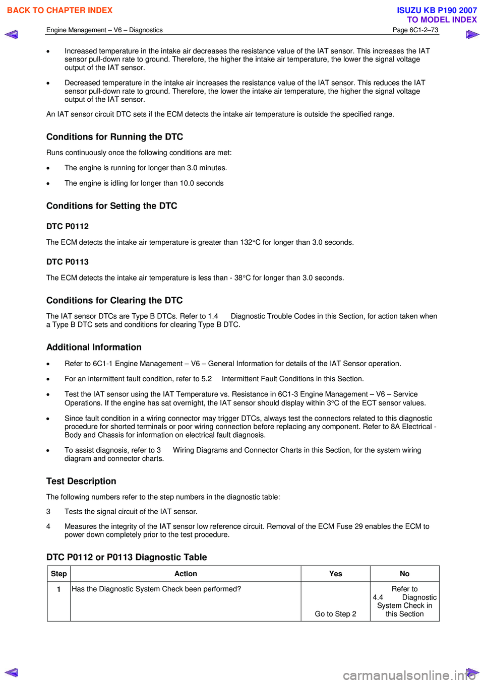
• Increased temperature in the intake air decreases the resistance value of the IAT sensor. This increases the IAT
sensor pull-down rate to ground. Therefore, the higher the intake air temperature, the lower the signal voltage
output of the IAT sensor.
• Decreased temperature in the intake air increases the resistance value of the IAT sensor. This reduces the IAT
sensor pull-down rate to ground. Therefore, the lower the intake air temperature, the higher the signal voltage
output of the IAT sensor.
An IAT sensor circuit DTC sets if the ECM detects the intake air temperature is outside the specified range.
Conditions for Running the DTC
Runs continuously once the following conditions are met:
• The engine is running for longer than 3.0 minutes.
• The engine is idling for longer than 10.0 seconds
Conditions for Setting the DTC
DTC P0112
The ECM detects the intake air temperature is greater than 132 °C for longer than 3.0 seconds.
DTC P0113
The ECM detects the intake air temperature is less than - 38 °C for longer than 3.0 seconds.
Conditions for Clearing the DTC
The IAT sensor DTCs are Type B DTCs. Refer to 1.4 Diagnostic Trouble Codes in this Section, for action taken when
a Type B DTC sets and conditions for clearing Type B DTC.
Additional Information
• Refer to 6C1-1 Engine Management – V6 – General Information for details of the IAT Sensor operation.
• For an intermittent fault condition, refer to 5.2 Intermittent Fault Conditions in this Section.
• Test the IAT sensor using the IAT Temperature vs. Resistance in 6C1-3 Engine Management – V6 – Service
Operations. If the engine has sat overnight, the IAT sensor should display within 3 °C of the ECT sensor values.
• Since fault condition in a wiring connector may trigger DTCs, always test the connectors related to this diagnostic
procedure for shorted terminals or poor wiring connection before replacing any component. Refer to 8A Electrical -
Body and Chassis for information on electrical fault diagnosis.
• To assist diagnosis, refer to 3 W iring Diagrams and Connector Charts in this Section, for the system wiring
diagram and connector charts.
Test Description
The following numbers refer to the step numbers in the diagnostic table:
3 Tests the signal circuit of the IAT sensor.
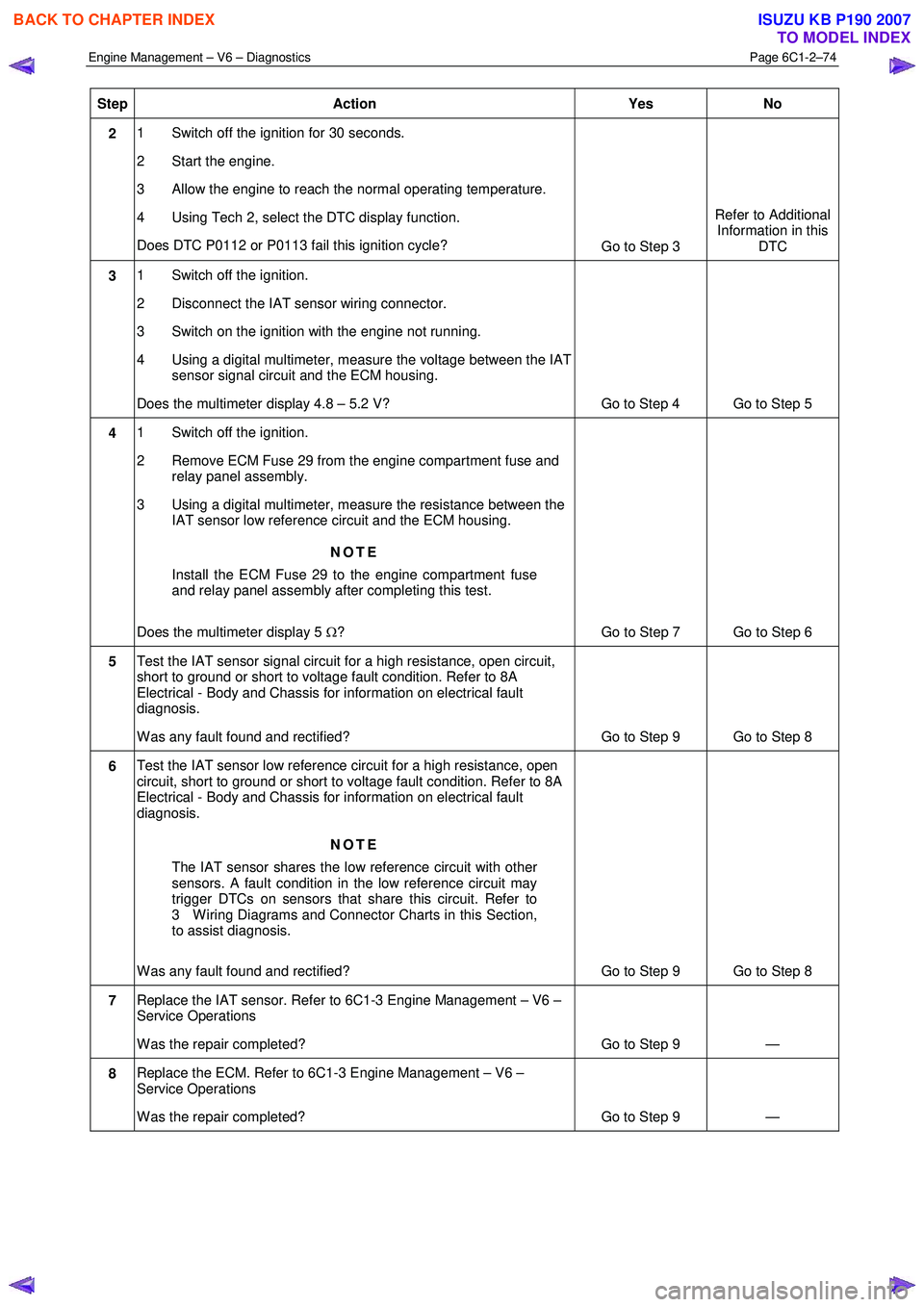
4 Measures the integrity of the IAT sensor low reference circuit. Removal of the ECM Fuse 29 enables the ECM to power down completely prior to the test procedure.
DTC P0112 or P0113 Diagnostic Table
Step Action Yes No
1 Has the Diagnostic System Check been performed?
Go to Step 2 Refer to
4.4 Diagnostic System Check in this Section
BACK TO CHAPTER INDEX
TO MODEL INDEX
ISUZU KB P190 2007
Page 3352 of 6020
Engine Management – V6 – Diagnostics Page 6C1-2–74
Step Action Yes No
2 1 Switch off the ignition for 30 seconds.
2 Start the engine.
3 Allow the engine to reach the normal operating temperature.
4 Using Tech 2, select the DTC display function.
Does DTC P0112 or P0113 fail this ignition cycle? Go to Step 3 Refer to Additional
Information in this DTC
3 1 Switch off the ignition.
2 Disconnect the IAT sensor wiring connector.
3 Switch on the ignition with the engine not running.
4 Using a digital multimeter, measure the voltage between the IAT sensor signal circuit and the ECM housing.
Does the multimeter display 4.8 – 5.2 V? Go to Step 4 Go to Step 5
4 1 Switch off the ignition.
2 Remove ECM Fuse 29 from the engine compartment fuse and relay panel assembly.
3 Using a digital multimeter, measure the resistance between the IAT sensor low reference circuit and the ECM housing.
NOTE
Install the ECM Fuse 29 to the engine compartment fuse
and relay panel assembly after completing this test.
Does the multimeter display 5 Ω? Go to Step 7 Go to Step 6
5 Test the IAT sensor signal circuit for a high resistance, open circuit,
short to ground or short to voltage fault condition. Refer to 8A
Electrical - Body and Chassis for information on electrical fault
diagnosis.
W as any fault found and rectified? Go to Step 9 Go to Step 8
6 Test the IAT sensor low reference circuit for a high resistance, open
circuit, short to ground or short to voltage fault condition. Refer to 8A
Electrical - Body and Chassis for information on electrical fault
diagnosis.
NOTE
The IAT sensor shares the low reference circuit with other
sensors. A fault condition in the low reference circuit may
trigger DTCs on sensors that share this circuit. Refer to
3 W iring Diagrams and Connector Charts in this Section,
to assist diagnosis.
W as any fault found and rectified? Go to Step 9 Go to Step 8
7 Replace the IAT sensor. Refer to 6C1-3 Engine Management – V6 –
Service Operations
W as the repair completed? Go to Step 9 —
8 Replace the ECM. Refer to 6C1-3 Engine Management – V6 –
Service Operations
W as the repair completed? Go to Step 9 —
BACK TO CHAPTER INDEX
TO MODEL INDEX
ISUZU KB P190 2007
Page 3355 of 6020
Engine Management – V6 – Diagnostics Page 6C1-2–77
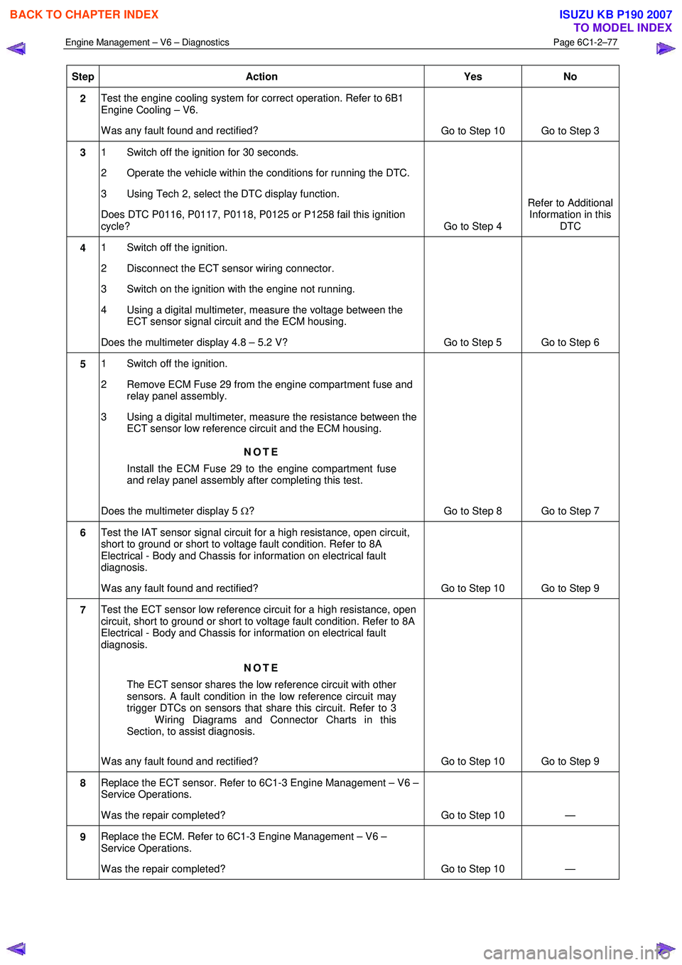
Step Action Yes No
2 Test the engine cooling system for correct operation. Refer to 6B1
Engine Cooling – V6.
W as any fault found and rectified? Go to Step 10 Go to Step 3
3 1 Switch off the ignition for 30 seconds.
2 Operate the vehicle within the conditions for running the DTC.
3 Using Tech 2, select the DTC display function.
Does DTC P0116, P0117, P0118, P0125 or P1258 fail this ignition
cycle? Go to Step 4 Refer to Additional
Information in this DTC
4 1 Switch off the ignition.
2 Disconnect the ECT sensor wiring connector.
3 Switch on the ignition with the engine not running.
4 Using a digital multimeter, measure the voltage between the ECT sensor signal circuit and the ECM housing.
Does the multimeter display 4.8 – 5.2 V? Go to Step 5 Go to Step 6
5 1 Switch off the ignition.
2 Remove ECM Fuse 29 from the engine compartment fuse and relay panel assembly.
3 Using a digital multimeter, measure the resistance between the ECT sensor low reference circuit and the ECM housing.
NOTE
Install the ECM Fuse 29 to the engine compartment fuse
and relay panel assembly after completing this test.
Does the multimeter display 5 Ω? Go to Step 8 Go to Step 7
6 Test the IAT sensor signal circuit for a high resistance, open circuit,
short to ground or short to voltage fault condition. Refer to 8A
Electrical - Body and Chassis for information on electrical fault
diagnosis.
W as any fault found and rectified? Go to Step 10 Go to Step 9
7 Test the ECT sensor low reference circuit for a high resistance, open
circuit, short to ground or short to voltage fault condition. Refer to 8A
Electrical - Body and Chassis for information on electrical fault
diagnosis.
NOTE
The ECT sensor shares the low reference circuit with other
sensors. A fault condition in the low reference circuit may
trigger DTCs on sensors that share this circuit. Refer to 3
W iring Diagrams and Connector Charts in this
Section, to assist diagnosis.
W as any fault found and rectified? Go to Step 10 Go to Step 9
8 Replace the ECT sensor. Refer to 6C1-3 Engine Management – V6 –
Service Operations.
W as the repair completed? Go to Step 10 —
9 Replace the ECM. Refer to 6C1-3 Engine Management – V6 –
Service Operations.
W as the repair completed? Go to Step 10 —
BACK TO CHAPTER INDEX
TO MODEL INDEX
ISUZU KB P190 2007
Page 3374 of 6020
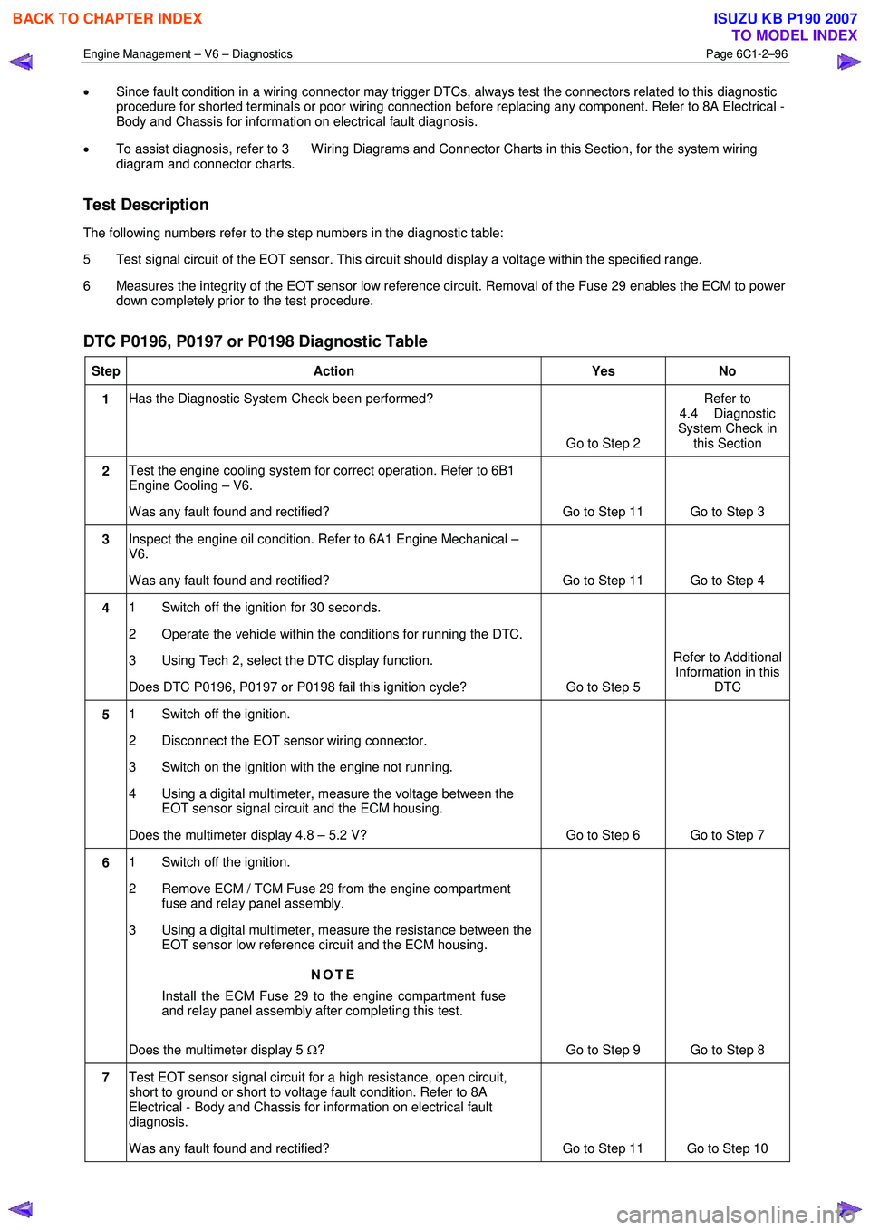
Engine Management – V6 – Diagnostics Page 6C1-2–96
• Since fault condition in a wiring connector may trigger DTCs, always test the connectors related to this diagnostic
procedure for shorted terminals or poor wiring connection before replacing any component. Refer to 8A Electrical -
Body and Chassis for information on electrical fault diagnosis.
• To assist diagnosis, refer to 3 W iring Diagrams and Connector Charts in this Section, for the system wiring
diagram and connector charts.
Test Description
The following numbers refer to the step numbers in the diagnostic table:
5 Test signal circuit of the EOT sensor. This circuit should display a voltage within the specified range.
6 Measures the integrity of the EOT sensor low reference circuit. Removal of the Fuse 29 enables the ECM to power down completely prior to the test procedure.
DTC P0196, P0197 or P0198 Diagnostic Table
Step Action Yes No
1 Has the Diagnostic System Check been performed?
Go to Step 2 Refer to
4.4 Diagnostic
System Check in this Section
2 Test the engine cooling system for correct operation. Refer to 6B1
Engine Cooling – V6.
W as any fault found and rectified? Go to Step 11 Go to Step 3
3 Inspect the engine oil condition. Refer to 6A1 Engine Mechanical –
V6.
W as any fault found and rectified? Go to Step 11 Go to Step 4
4 1 Switch off the ignition for 30 seconds.
2 Operate the vehicle within the conditions for running the DTC.
3 Using Tech 2, select the DTC display function.
Does DTC P0196, P0197 or P0198 fail this ignition cycle? Go to Step 5 Refer to Additional
Information in this DTC
5 1 Switch off the ignition.
2 Disconnect the EOT sensor wiring connector.
3 Switch on the ignition with the engine not running.
4 Using a digital multimeter, measure the voltage between the EOT sensor signal circuit and the ECM housing.
Does the multimeter display 4.8 – 5.2 V? Go to Step 6 Go to Step 7
6 1 Switch off the ignition.
2 Remove ECM / TCM Fuse 29 from the engine compartment fuse and relay panel assembly.
3 Using a digital multimeter, measure the resistance between the EOT sensor low reference circuit and the ECM housing.
NOTE
Install the ECM Fuse 29 to the engine compartment fuse
and relay panel assembly after completing this test.
Does the multimeter display 5 Ω? Go to Step 9 Go to Step 8
7 Test EOT sensor signal circuit for a high resistance, open circuit,
short to ground or short to voltage fault condition. Refer to 8A
Electrical - Body and Chassis for information on electrical fault
diagnosis.
W as any fault found and rectified? Go to Step 11 Go to Step 10
BACK TO CHAPTER INDEX
TO MODEL INDEX
ISUZU KB P190 2007
Page 3384 of 6020
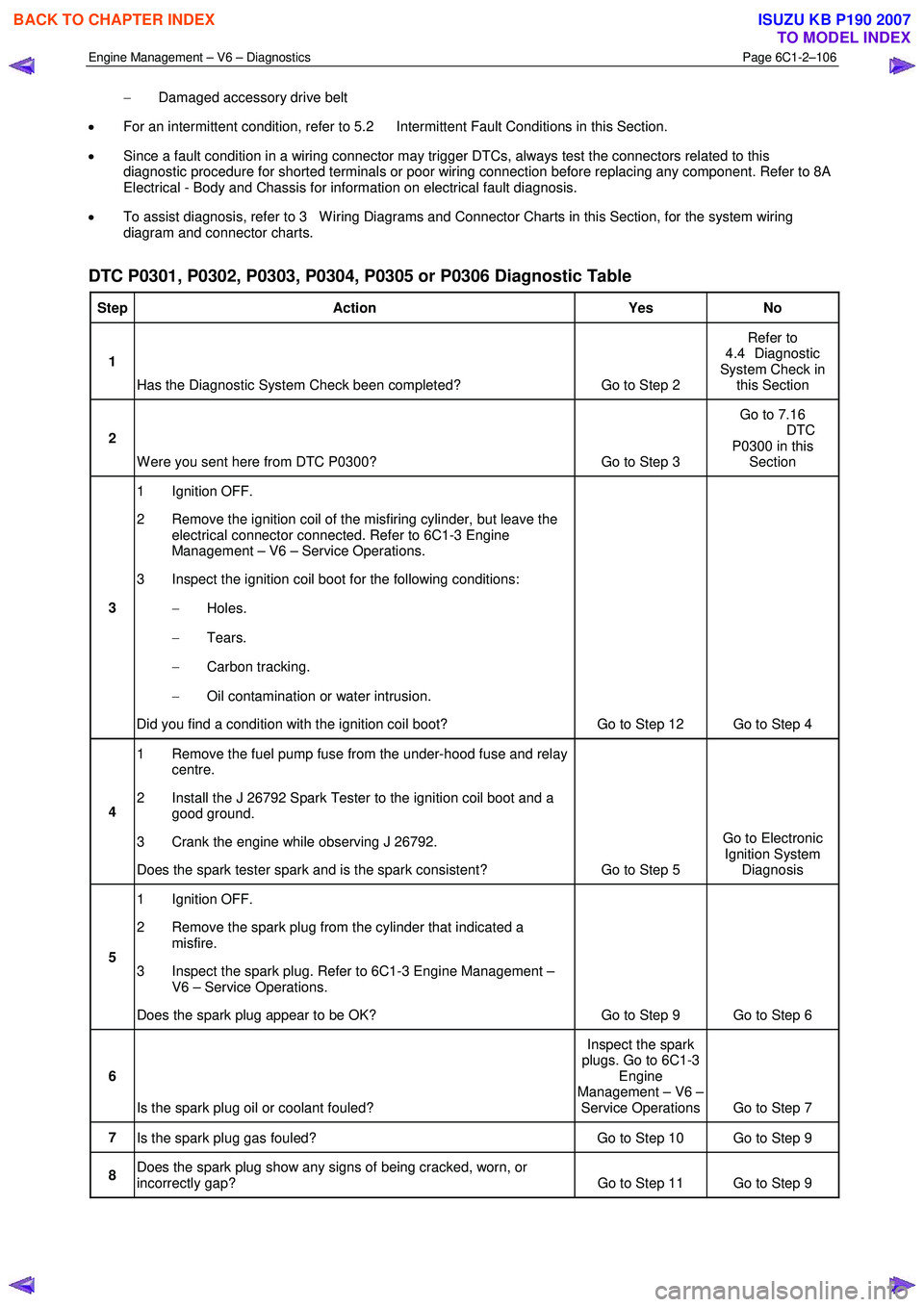
Engine Management – V6 – Diagnostics Page 6C1-2–106
− Damaged accessory drive belt
• For an intermittent condition, refer to 5.2 Intermittent Fault Conditions in this Section.
• Since a fault condition in a wiring connector may trigger DTCs, always test the connectors related to this
diagnostic procedure for shorted terminals or poor wiring connection before replacing any component. Refer to 8A
Electrical - Body and Chassis for information on electrical fault diagnosis.
• To assist diagnosis, refer to 3 W iring Diagrams and Connector Charts in this Section, for the system wiring
diagram and connector charts.
DTC P0301, P0302, P0303, P0304, P0305 or P0306 Diagnostic Table
Step Action Yes No
1
Has the Diagnostic System Check been completed? Go to Step 2 Refer to
4.4 Diagnostic
System Check in this Section
2
W ere you sent here from DTC P0300? Go to Step 3 Go to 7.16
DTC P0300 in this Section
3 1 Ignition OFF.
2 Remove the ignition coil of the misfiring cylinder, but leave the electrical connector connected. Refer to 6C1-3 Engine
Management – V6 – Service Operations.
3 Inspect the ignition coil boot for the following conditions:
− Holes.
− Tears.
− Carbon tracking.
− Oil contamination or water intrusion.
Did you find a condition with the ignition coil boot? Go to Step 12 Go to Step 4
4 1 Remove the fuel pump fuse from the under-hood fuse and relay
centre.
2 Install the J 26792 Spark Tester to the ignition coil boot and a good ground.
3 Crank the engine while observing J 26792.
Does the spark tester spark and is the spark consistent? Go to Step 5 Go to Electronic
Ignition System Diagnosis
5 1 Ignition OFF.
2 Remove the spark plug from the cylinder that indicated a misfire.
3 Inspect the spark plug. Refer to 6C1-3 Engine Management – V6 – Service Operations.
Does the spark plug appear to be OK? Go to Step 9 Go to Step 6
6
Is the spark plug oil or coolant fouled? Inspect the spark
plugs. Go to 6C1-3 Engine
Management – V6 – Service Operations Go to Step 7
7 Is the spark plug gas fouled? Go to Step 10 Go to Step 9
8 Does the spark plug show any signs of being cracked, worn, or
incorrectly gap? Go to Step 11 Go to Step 9
BACK TO CHAPTER INDEX
TO MODEL INDEX
ISUZU KB P190 2007