check engine light ISUZU KB P190 2007 Workshop User Guide
[x] Cancel search | Manufacturer: ISUZU, Model Year: 2007, Model line: KB P190, Model: ISUZU KB P190 2007Pages: 6020, PDF Size: 70.23 MB
Page 830 of 6020
ENGINE MECHANICAL 6A – 25
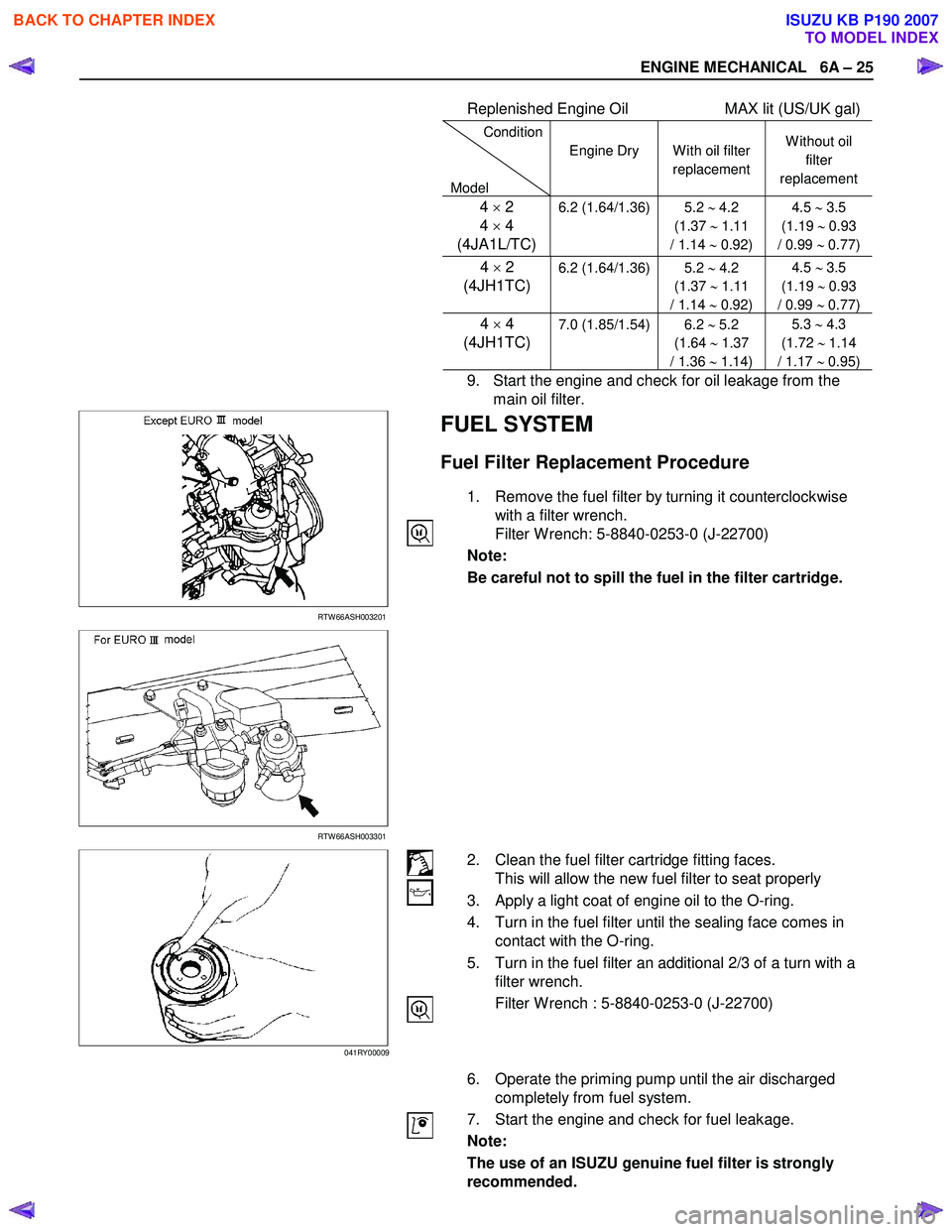
Replenished Engine Oil MAX lit (US/UK gal)
Condition
Model Engine Dry
W ith oil filter
replacement W ithout oil
filter
replacement
4 × 2
4 × 4
(4JA1L/TC)6.2 (1.64/1.36) 5.2 ∼ 4.2
(1.37 ∼ 1.11
/ 1.14 ∼ 0.92) 4.5
∼ 3.5
(1.19 ∼ 0.93
/ 0.99 ∼ 0.77)
4 × 2
(4JH1TC)
6.2 (1.64/1.36) 5.2
∼ 4.2
(1.37 ∼ 1.11
/ 1.14 ∼ 0.92) 4.5
∼ 3.5
(1.19 ∼ 0.93
/ 0.99 ∼ 0.77)
4 × 4
(4JH1TC) 7.0 (1.85/1.54) 6.2 ∼ 5.2
(1.64 ∼ 1.37
/ 1.36 ∼ 1.14) 5.3
∼ 4.3
(1.72 ∼ 1.14
/ 1.17 ∼ 0.95)
9. Start the engine and check for oil leakage from the
main oil filter.
RTW 66ASH003201
FUEL SYSTEM
Fuel Filter Replacement Procedure
1. Remove the fuel filter by turning it counterclockwise with a filter wrench.
Filter W rench: 5-8840-0253-0 (J-22700)
Note:
Be careful not to spill the fuel in the filter cartridge.
RTW 66ASH003301
2. Clean the fuel filter cartridge fitting faces. This will allow the new fuel filter to seat properly
3. Apply a light coat of engine oil to the O-ring.
4. Turn in the fuel filter until the sealing face comes in contact with the O-ring.
5. Turn in the fuel filter an additional 2/3 of a turn with a filter wrench.
Filter W rench : 5-8840-0253-0 (J-22700)
6. Operate the priming pump until the air discharged completely from fuel system.
7. Start the engine and check for fuel leakage.
Note:
The use of an ISUZU genuine fuel filter is strongly
recommended.
041RY00009
BACK TO CHAPTER INDEX
TO MODEL INDEX
ISUZU KB P190 2007
Page 831 of 6020
6A – 26 ENGINE MECHANICAL
041RY00011
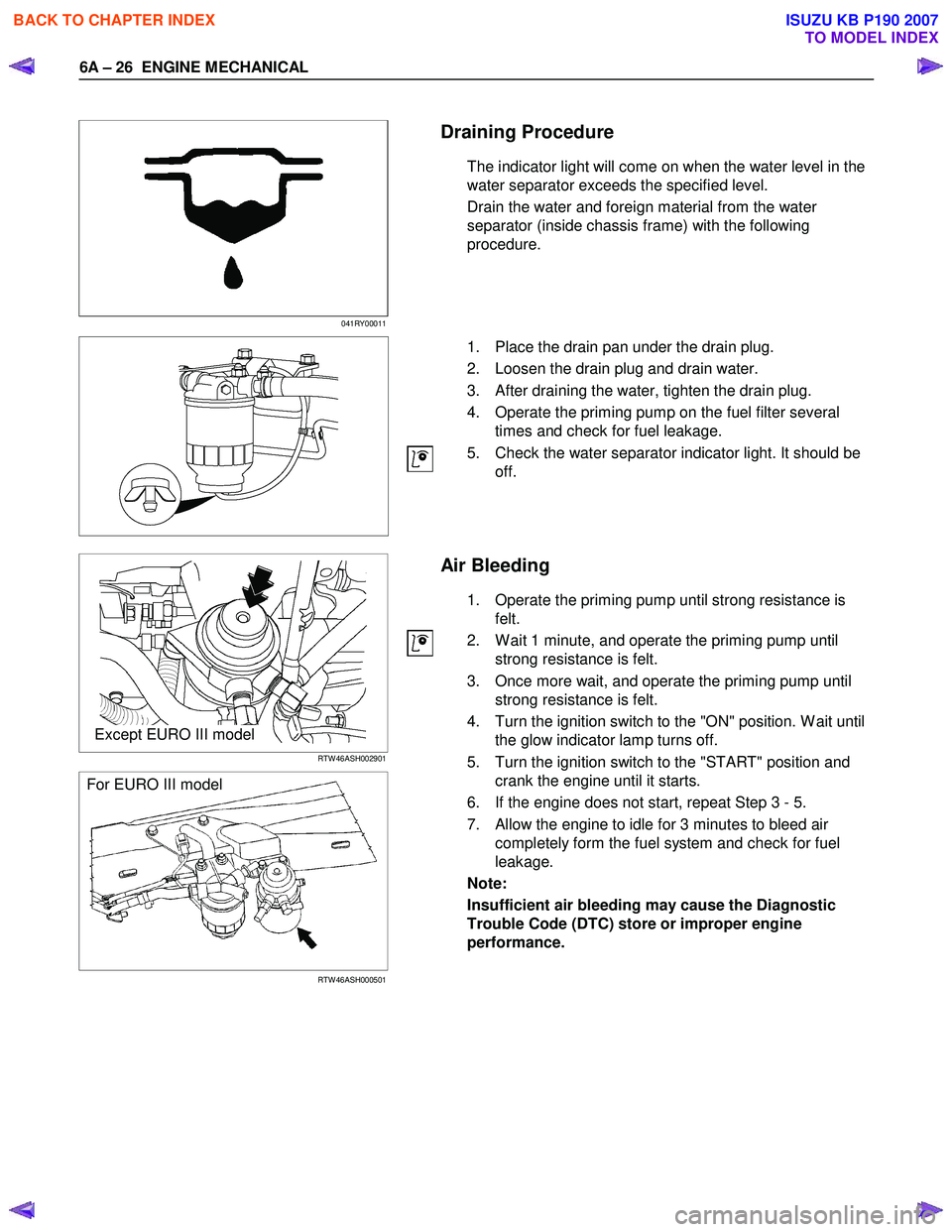
Draining Procedure
The indicator light will come on when the water level in the
water separator exceeds the specified level.
Drain the water and foreign material from the water
separator (inside chassis frame) with the following
procedure.
1. Place the drain pan under the drain plug.
2. Loosen the drain plug and drain water.
3. After draining the water, tighten the drain plug.
4. Operate the priming pump on the fuel filter several times and check for fuel leakage.
5. Check the water separator indicator light. It should be off.
Except EURO III model
RTW 46ASH002901
For EURO III model
RTW 46ASH000501
Air Bleeding
1. Operate the priming pump until strong resistance is felt.
2. W ait 1 minute, and operate the priming pump until strong resistance is felt.
3. Once more wait, and operate the priming pump until strong resistance is felt.
4. Turn the ignition switch to the "ON" position. W ait until the glow indicator lamp turns off.
5. Turn the ignition switch to the "START" position and crank the engine until it starts.
6. If the engine does not start, repeat Step 3 - 5.
7. Allow the engine to idle for 3 minutes to bleed air completely form the fuel system and check for fuel
leakage.
Note:
Insufficient air bleeding may cause the Diagnostic
Trouble Code (DTC) store or improper engine
performance.
BACK TO CHAPTER INDEX
TO MODEL INDEX
ISUZU KB P190 2007
Page 836 of 6020
ENGINE MECHANICAL 6A – 31
VALVE CLEARANCE ADJUSTMENT
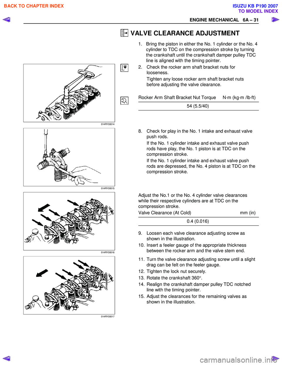
1. Bring the piston in either the No. 1 cylinder or the No. 4 cylinder to TDC on the compression stroke by turning
the crankshaft until the crankshaft damper pulley TDC
line is aligned with the timing pointer.
014RY00014
2. Check the rocker arm shaft bracket nuts for
looseness.
Tighten any loose rocker arm shaft bracket nuts
before adjusting the valve clearance.
Rocker Arm Shaft Bracket Nut Torque N·m (kg·m /lb·ft)
54 (5.5/40)
014RY00015
8. Check for play in the No. 1 intake and exhaust valve
push rods.
If the No. 1 cylinder intake and exhaust valve push
rods have play, the No. 1 piston is at TDC on the
compression stroke.
If the No. 1 cylinder intake and exhaust valve push
rods are depressed, the No. 4 piston is at TDC on the
compression stroke.
014RY00016
Adjust the No.1 or the No. 4 cylinder valve clearances
while their respective cylinders are at TDC on the
compression stroke.
Valve Clearance (At Cold) mm (in)
0.4 (0.016)
9. Loosen each valve clearance adjusting screw as
shown in the illustration.
10. Insert a feeler gauge of the appropriate thickness between the rocker arm and the valve stem end.
014RY00017
11. Turn the valve clearance adjusting screw until a slight
drag can be felt on the feeler gauge.
12. Tighten the lock nut securely.
13. Rotate the crankshaft 360 °.
14. Realign the crankshaft damper pulley TDC notched line with the timing pointer.
15. Adjust the clearances for the remaining valves as shown in the illustration.
BACK TO CHAPTER INDEX
TO MODEL INDEX
ISUZU KB P190 2007
Page 838 of 6020

ENGINE MECHANICAL 6A – 33
INJECTION TIMING ADJUSTMENT
(4JA1T(L) only)
1. Check that the notched line on the injection pump
flange is aligned with the front plate or the timing gear
case notched line.
2. Bring the piston in the No. 1 cylinder to TDC on the
compression stroke by turning the crankshaft until the
crankshaft pulley TDC line is aligned with the timing
mark.
Note:
Check for play in the No. 1 intake and exhaust valve
push rods.
If the No. 1 cylinder intake and exhaust valve push
rods have play, the No. 1 piston is at TDC on the
compression stroke.
RTW 46ASH000601
3. Disconnect the injection pipe from the injection pump
4. Remove one bolt from the distributor head.
5. Install the adapter set, togather with static timing gauge.
The probe of the gauge should be depressed inward
approximately 2 mm (0.079 in).
Static Timing Gauge: 5-8840-0145-0 (J-28827)
Adapter Set: Static Timing Gauge: 5-8840-2834-0
RTW 36ASH002101 6. Rotate the crankshaft to bring the piston in the No. 1
cylinder to a point 30 - 40 ° BTDC.
7. Set the timing gauge needle to zero.
8. Move the crankshaft pulley slightly in both directions to check that the gauge indication is stable.
BACK TO CHAPTER INDEX
TO MODEL INDEX
ISUZU KB P190 2007
Page 846 of 6020
ENGINE MECHANICAL 6A – 41
Coolant Replenishment
Warning:
When the coolant is heated to a high temperature, be
sure not to loosen or remove the rediator cap.
Otherwise you might get scalded by hot vapor or
boiling water.
To open the radiator cap, put a piece of thick cloth on
the cap and loosen the cap slowly to reduce the
pressure when the coolant has become cooler.
1. Open rediator cap pour coolant up to filler neck
2. Pour coolant into reservoir tank up to "MAX" line
3. Tighten radiator cap and start the engine. After idling for 2 to 3 minutes, stop the engine and reopen radiator
cap. If the water level is lower, replenish.
4. After replenish the coolant tighten radiator cap, warm up the engine at about 2000 rpm. Set heater
adjustment to the highest temperature position, and let
the coolant circulate also into heater water system.
5. Check to see the thermometer, continuously idling 5 minutes and stop the engine.
6. W hen the engine has been cooled, check filler neck for water level and replenish if required. Should extreme
shortage of coolant is found, check the coolant system
and reservoir tank hose for leakage.
7. Pour coolant into the reservoir tank up to "MAX" line.
Coolant Capacity lit (US/UK gal)
4JA1 / TC 9.4 (2.5 / 2.1)
4JH1TC M/T: 10.1 (2.7 / 2.2)
A/T: 10.0 (2.6 / 2.2)
Engine Warm-Up
After completing the required maintenance procedures,
start the engine and allow it to idle until it is warm.
Check the following:
1. Engine idling speed.
2. Engine noise level.
3. Engine lubricating system and cooling system. Carefully check for oil and coolant leakage.
4. Clutch engagement.
5. Transmission operation.
6. Indicator warning light operation.
BACK TO CHAPTER INDEX
TO MODEL INDEX
ISUZU KB P190 2007
Page 874 of 6020

ENGINE MECHANICAL 6A – 69
3. Check that the rocker arm oil port is free of obstructions. If necessary, use compressed air to clean the rocker arm
oil port.
Rocker Arm Correction
Inspect the rocker arm valve stem contact surfaces for step
wear (1) and scoring (2).
If the contact surfaces have light step wear or scoring, they
may be honed with an oil stone.
If the step wear or scoring is severe, the rocker arm must be
replaced.
CYLINDER BODY
Cylinder Body Upper Face Warpage
1. Remove the cylinder body dowel.
2. Remove the cylinder liner. Refer to "Cylinder Liner Replacement".
3. Use a straight edge (1) and a feeler gauge (2) to measure
the four sides and the two diagonals of the cylinder body
upper face.
If the measured values exceeds the limit, the cylinder body
must be replaced.
Cylinder Body Upper Face Warpage mm (in)
Standard Limit
0.05 (0.002) or less 0.20 (0.008)
Cylinder Body Height (H) (Reference) mm (in)
Standard
4JA1T(L), 4JA1TC : 244.945-245.055 (9.6435-9.6478)
4JH1TC : 269.945-270.055 (10.6277-10.6320)
4. Reinstall the cylinder liner. Refer to "Cylinder Liner Replacement".
5. Reinstall the cylinder body dowel.
014RY00024
012R100001
012RY00009 014RY00023
BACK TO CHAPTER INDEX
TO MODEL INDEX
ISUZU KB P190 2007
Page 979 of 6020

FUEL SYSTEM 6C – 15
140R100037
2. For removal of the quick connector, hold the quick
connector in one hand, and pull out the connector with the
other hand while pressing the square relieve button of the
connector, as illustrated.
NOTE: Do not use tools of any kind. Only use bare hands
when disconnecting the connector. Use a lubricant (light oil)
and/or push and pull the connector until the pipe is
disconnected.
140R100028
Cover the connectors that was removed with a plastic bag,
to prevent dust or rain water from entering.
140R100036
Reuse of Quick–Connector
• Replace the port and connector if scratch, dent or crack is
found.
• Remove any dirt build up on the port when installing the
connector. Replace the connector, if there is any forms o
f
rust, dent, scratch.
• After cleaning the port, insert it straight into the connecto
r
until it clicks. After it clicks, try pulling at 49N (5kgf) it out to
make sure that it is not drawn and is securely locked.
Assembling Advice
By applying engine oil or light oil to the pipe, port makes pipe
assembly easier. The pipe assembly should take place
immediately after applying oil (to prevent dust from sticking to
the pipe surface – which may decrease sealing ability). Test/Inspection After Assembling
1. Reconnect the battery negative cable.
2. Start the engine and observe the engine idle speed. The presence of dirt in the fuel system may affect the fuel
injection system.
3. Check for fuel leakage from the connector.
BACK TO CHAPTER INDEX
TO MODEL INDEX
ISUZU KB P190 2007
Page 1137 of 6020
Engine Control System (4JH1) 6E-103
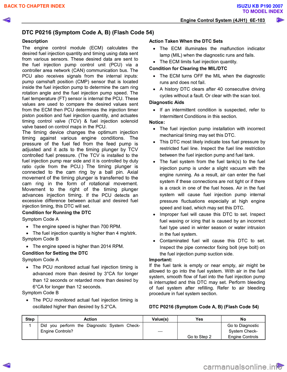
DTC P0216 (Symptom Code A, B) (Flash Code 54)
Description
The engine control module (ECM) calculates the
desired fuel injection quantity and timing using data sent
from various sensors. These desired data are sent to
the fuel injection pump control unit (PCU) via a
controller area network (CAN) communication bus. The
PCU also receives signals from the internal inputs:
pump camshaft position (CMP) sensor that is located
inside the fuel injection pump to determine the cam ring
rotation angle and the fuel injection pump speed. The
fuel temperature (FT) sensor is internal the PCU. These
values are used to compare the desired values sent
from the ECM then PCU determines the injection time
r
piston position and fuel injection quantity, and actuates
timing control valve (TCV) & fuel injection solenoid
valve based on control maps in the PCU.
The timing device changes the optimum injection
timing against various engine conditions. The
pressure of the fuel fed from the feed pump is
adjusted and it acts to the timing plunger by TCV
controlled fuel pressure. (
The TCV is installed to the
fuel injection pump rear side and it is controlled by dut
y
ratio cycle from the PCU.) The timing plunger is
connected to the cam ring by a ball pin. Axial
movement of the timing plunger is transferred to the
cam ring in the form of rotational movement.
Movement to the right of the timing plunge
r
advances injection timing.
If the PCU detects an
excessive difference between actual and desired fuel
injection timing, this DTC will set.
Condition for Running the DTC
Symptom Code A
• The engine speed is higher than 700 RPM.
• The fuel injection quantity is higher than 4 mg/strk.
Symptom Code B
• The engine speed is higher than 2014 RPM.
Condition for Setting the DTC
Symptom Code A
• The PCU monitored actual fuel injection timing is
advanced more than desired by 3°CA for longe
r
than 12 seconds or retarded more than desired by
6°CA for longer than 12 seconds.
Symptom Code B
• The PCU monitored actual fuel injection timing is
oscillated higher than desired by 5.2°CA.
Action Taken When the DTC Sets
• The ECM illuminates the malfunction indicato
r
lamp (MIL) when the diagnostic runs and fails.
• The ECM limits fuel injection quantity.
Condition for Clearing the MIL/DTC
• The ECM turns OFF the MIL when the diagnostic
runs and does not fail.
• A history DTC clears after 40 consecutive driving
cycles without a fault. Or clear with the scan tool.
Diagnostic Aids
• If an intermittent condition is suspected, refer to
Intermittent Conditions in this section.
Notice:
• The fuel injection pump installation with incorrect
mechanical timing may set this DTC.
• This DTC most likely indicate loss fuel pressure by
restricted fuel line. Inspect the fuel line restriction
between the fuel injection pump and fuel tank.
• The fuel system from the fuel tank(s) to the fuel
injection pump is under a slight vacuum with the
engine running. As a result, air can enter the fuel
system if these connections are not tight or if there
is a crack in one of the fuel hoses. Air in the fuel
system will cause fuel injection pump internal
pressure fluctuations especially at high engine
speed and load, which may set this DTC.
• Improper fuel will cause this DTC to set. Inspect
fuel waxing or icing that is caused by an incorrect
fuel type used in winter season or water intrusion
in the fuel system.
• Contaminated fuel will cause this DTC to set.
Inspect the pipe connector fixing bolt (eye bolt) on
the fuel injection pump suction side.
Important:
If the fuel tank is empty or near empty, air might be
allowed to go into the fuel system. W ith air in the fuel
system, smooth flow of fuel into the fuel injection pump
is interrupted and this DTC may set. Perform bleeding
of fuel system after refilling. Refer to air bleeding
procedure in fuel system section.
DTC P0216 (Symptom Code A, B) (Flash Code 54)
Step Action Value(s) Yes No
1 Did you perform the Diagnostic System Check-
Engine Controls?
Go to Step 2 Go to Diagnostic
System Check-
Engine Controls
BACK TO CHAPTER INDEX
TO MODEL INDEX
ISUZU KB P190 2007
Page 1138 of 6020

6E-104 Engine Control System (4JH1)
Step Action Value(s) Yes No
2 1. Install the scan tool.
2. Turn OFF the ignition for 30 seconds.
3. Start the engine and let idle for 30 seconds.
4. Monitor the Diagnostic Trouble Code (DTC) Information with the scan tool.
Is DTC P0335 (Symptom Code B or D), P1335
(Symptom Code A) or P1345 (Symptom Code A)
set?
Go to Applicable DTC Go to Step 3
3 1. Turn OFF the engine. 2. Place the transmission in park or neutral (P or N) and set the park brake.
3. Start the engine and let engine idle for 30 seconds while observing the Actual Injection
Timing parameter with the scan tool.
4. Accelerate the engine and keep the constant engine speed around 2000 RPM while observing
the Actual Injection Timing parameter with the
scan tool.
5. Accelerate the engine and keep the constant engine speed around 3000 RPM while observing
the Actual Injection Timing parameter with the
scan tool.
Does the Actual Injection Timing parameter follow
the Desired Injection Timing within 2°CA on each
engine speed?
Go to Diagnostic Aids Go to Step 4
4 1. Turn OFF the ignition. 2. Check the fuel system line connections between the fuel tank and the fuel injection pump for
tightness and all fuel hoses for cuts, cracks and
for the use of proper clamps.
Notice: The fuel system from the fuel tank(s) to the
fuel injection pump is under a slight vacuum with the
engine running. As a result, air can enter the fuel
system if these connections are not tight. Air in the
fuel system will cause fuel injection pump internal
pressure fluctuations especially at high engine
speed and load, which may set this DTC.
3. Pump the priming pump on the fuel filter until it becomes firm. If there is a leak on the suction
side of the fuel system between the priming
pump and the fuel injection pump, the priming
pump will not build up sufficient firmness and fuel
leakage may occur.
4. Repair or replace as necessary.
Did you find and correct the condition?
Go to Step 9 Go to Step 5
BACK TO CHAPTER INDEX
TO MODEL INDEX
ISUZU KB P190 2007
Page 1164 of 6020

6E-130 Engine Control System (4JH1)
DTC P0335 (Symptom Code B, D) (Flash Code 43)
Circuit Description
The crankshaft position (CKP) sensor is located on top
of the flywheel housing. There are 4 slits spaced 90 °
on the flywheel circumference. The CKP sensor is a
magnetic coil type sensor, which generates an AC
signal voltage based on the crankshaft rotational speed.
The engine control module (ECM) monitors both the
CKP sensor and injection pump camshaft position
(CMP) sensor signals to ensure they correlate with each
other.
If the ECM receives extra or missing CKP sensor signal
pulses, this DTC will set. (Symptom Code B)
If the ECM receives a certain amount of injection pump
CMP sensor signal pulses without a CKP sensor signal,
this DTC will set. (Symptom Code D)
Condition for Running the DTC
Symptom Code B • The ignition switch is ON.
• The engine speed is higher than 665 RPM
Symptom Code D • DTC P0335 (Symptom Code B) is not set.
• The ignition switch is ON.
• The fuel injection pump CMP sensor signal is
generated.
• The controller area network (CAN) communication
between the ECM and PCU is normal.
Condition for Setting the DTC
Symptom Code B • The ECM detects extra or missing CKP senso
r
signals while engine is running.
Symptom Code D
• The ECM detects that the CKP sensor signals are
not generated when doubled fuel injection pump
rotation speed is higher than 50 RPM.
Action Taken When the DTC Sets
• The ECM illuminates the malfunction indicato
r
lamp (MIL) when the diagnostic runs and fails.
The ECM uses an engine speed substitution o
f
doubled fuel injection pump speed for engine
control.
Condition for Clearing the MIL/DTC
• The ECM turns OFF the MIL when the diagnostic
runs and does not fail.
• A history DTC clears after 40 consecutive driving
cycles without a fault. Or clear with the scan tool.
Diagnostic Aids
• If an intermittent condition is suspected, refer to
Intermittent Conditions in this section.
• Ensure the sensor is tight and the flywheel
circumference is not damaged.
DTC P0335 (Symptom Code B, D) (Flash Code 43)
Schematic Reference: Engine Controls Schematics
Connector End View Reference: Engine Controls
Connector End Views or Engine Control Module (ECM)
Connector End Views
Step Action Value(s) Yes No
1 Did you perform the Diagnostic System Check-
Engine Controls?
Go to Step 2 Go to Diagnostic
System Check-
Engine Controls
2 1. Install the scan tool. 2. Turn OFF the ignition for 30 seconds.
3. Start the engine (Note a slight start delay may be noticed).
4. Monitor the Diagnostic Trouble Code (DTC) Information with the scan tool.
Does the DTC fail this ignition?
Go to Step 3 Go to Diagnostic
Aids
3 1. Turn OFF the ignition. 2. Disconnect the crankshaft position sensor (CKP) harness connector.
3. Connect a DMM across the CKP sensor terminals (pins 1 and 2 of E-9 connector).
4. Measure the resistance across the CKP sensor.
Is the CKP sensor resistance within the specified
value? 870 – 930
Ω
Go to Step 4 Go to Step 20
BACK TO CHAPTER INDEX
TO MODEL INDEX
ISUZU KB P190 2007