coolant level ISUZU KB P190 2007 Workshop Repair Manual
[x] Cancel search | Manufacturer: ISUZU, Model Year: 2007, Model line: KB P190, Model: ISUZU KB P190 2007Pages: 6020, PDF Size: 70.23 MB
Page 787 of 6020
6 – 2 TROUBLESHOOTING
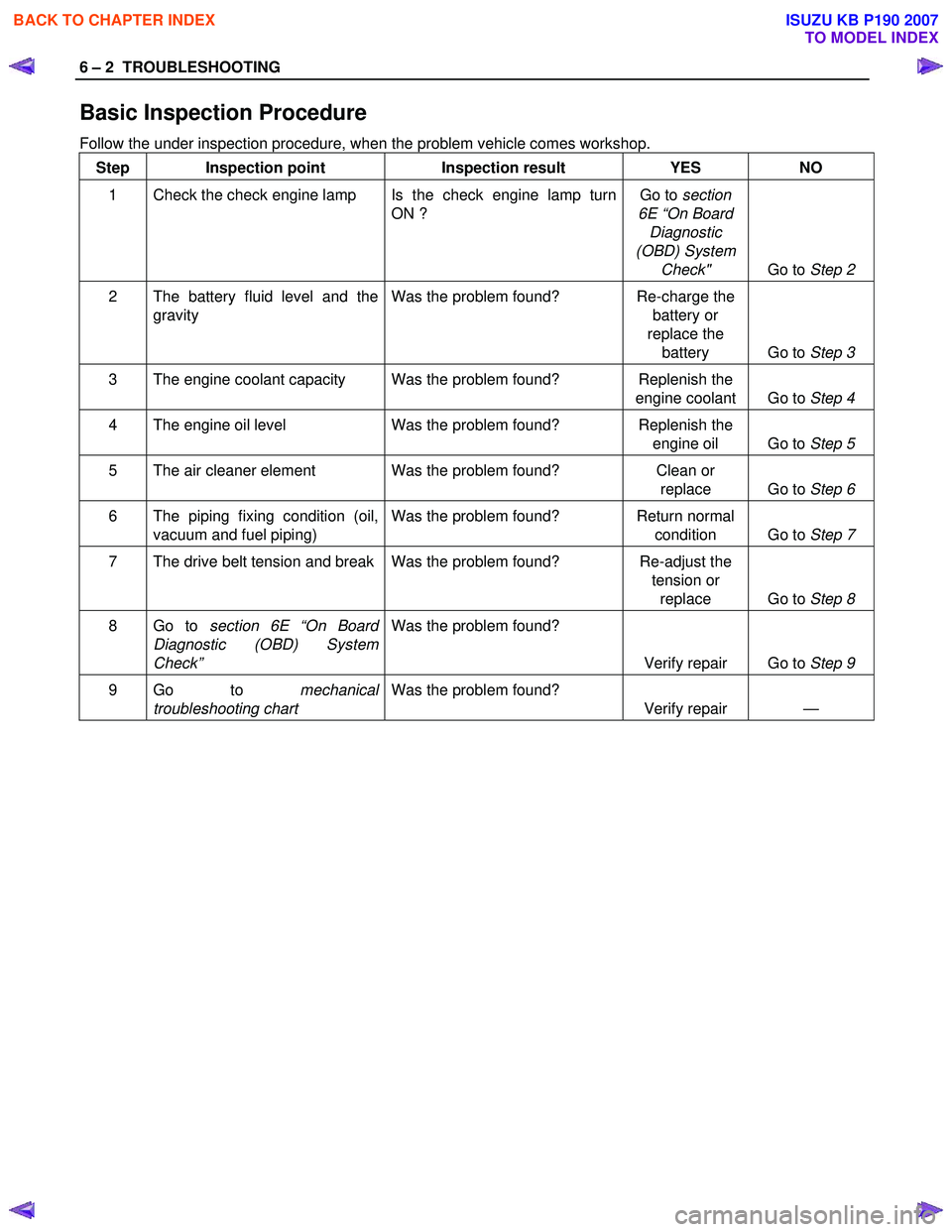
Basic Inspection Procedure
Follow the under inspection procedure, when the problem vehicle comes workshop. Step Inspection point Inspection result YES NO
1 Check the check engine lamp Is the check engine lamp turn ON ? Go to
section
6E “On Board Diagnostic
(OBD) System Check" Go to Step 2
2 The battery fluid level and the
gravity Was the problem found? Re-charge the
battery or
replace the battery Go to Step 3
3 The engine coolant capacity Was the problem found? Replenish the
engine coolant Go to Step 4
4 The engine oil level Was the problem found? Replenish the
engine oil Go to Step 5
5 The air cleaner element Was the problem found? Clean or
replace Go to Step 6
6 The piping fixing condition (oil,
vacuum and fuel piping) Was the problem found? Return normal
condition Go to Step 7
7 The drive belt tension and break Was the problem found? Re-adjust the
tension or replace Go to Step 8
8 Go to section 6E “On Board
Diagnostic (OBD) System
Check” Was the problem found?
Verify repair Go to Step 9
9 Go to mechanical
troubleshooting chart Was the problem found?
Verify repair —
BACK TO CHAPTER INDEX
TO MODEL INDEX
ISUZU KB P190 2007
Page 794 of 6020

TROUBLESHOOTING 6 – 9
6. Overheating
Step Action Value(s) Yes No
1 Was the engine coolant level OK? —
Go to Step 2 Replenish the
coolant
2 Was the water leakage or the radiator restriction found? (Include radiator cap) —
Repair or
replace the
leakage part. Go to Step 3
3 Was the fan belt slippage found? — Tension or
replace the fan belt. Go to Step 4
4 Was the fan clutch working completely? —
Go to Step 5 Replace the fan
clutch
assembly.
5 Was the oil leakage found from fan clutch? — Replace the fan
clutch
assembly Go to Step 6
6 Was the thermostat working normally? —
Go to Step 7 Replace the
thermostat.
7 Was the water pump working OK? —
Go to Step 8 Replace the
water pump assembly.
8 Was the restriction by the foreign materials in the cooling system found? For example, clog the water
hose between the cylinder body and radiator etc.. —
Clean or
replace the clog part. Go to Step 9
9 Was the water leakage found from the sealing cap
on the cylinder body? —
Replace the
sealing cap or replace the
cylinder body. Go to Step 10
10 Are any DTC stored? — Go to indicated
DTC. Solved
7. White Exhaust Smoke
Step Action Value(s) Yes No
1 Was the compression pressure OK? 3.0 MPa
(31.0 kg/cm2,
441 psi) at 200 rpm
Go to Step 2 Readjust the
valve clearance or replace the cylinder head gasket or
cylinder liner or
piston or piston ring or valve and relation parts.
2 Was the PCV (Positive Crankcase Ventilation) valve working completely? —
Go to Step 3 Repair or
replace the
PCV valve.
3 Was the turbocharger working completely? —
Go to Step 4 Replace the
turbocharger.
4 Are any DTC stored? — Go to indicated
DTC Solved
BACK TO CHAPTER INDEX
TO MODEL INDEX
ISUZU KB P190 2007
Page 832 of 6020
ENGINE MECHANICAL 6A – 27
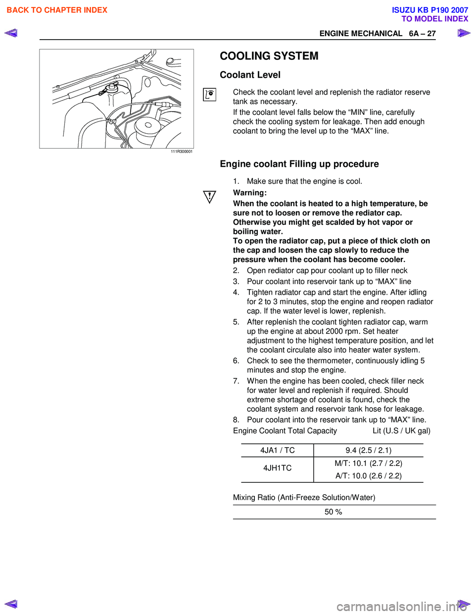
111R300001
COOLING SYSTEM
Coolant Level
Check the coolant level and replenish the radiator reserve
tank as necessary.
If the coolant level falls below the “MIN” line, carefully
check the cooling system for leakage. Then add enough
coolant to bring the level up to the “MAX” line.
Engine coolant Filling up procedure
1. Make sure that the engine is cool.
Warning:
When the coolant is heated to a high temperature, be
sure not to loosen or remove the rediator cap.
Otherwise you might get scalded by hot vapor or
boiling water.
To open the radiator cap, put a piece of thick cloth on
the cap and loosen the cap slowly to reduce the
pressure when the coolant has become cooler.
2. Open rediator cap pour coolant up to filler neck
3. Pour coolant into reservoir tank up to “MAX” line
4. Tighten radiator cap and start the engine. After idling for 2 to 3 minutes, stop the engine and reopen radiator
cap. If the water level is lower, replenish.
5. After replenish the coolant tighten radiator cap, warm up the engine at about 2000 rpm. Set heater
adjustment to the highest temperature position, and let
the coolant circulate also into heater water system.
6. Check to see the thermometer, continuously idling 5 minutes and stop the engine.
7. W hen the engine has been cooled, check filler neck for water level and replenish if required. Should
extreme shortage of coolant is found, check the
coolant system and reservoir tank hose for leakage.
8. Pour coolant into the reservoir tank up to “MAX” line.
Engine Coolant Total Capacity Lit (U.S / UK gal)
4JA1 / TC 9.4 (2.5 / 2.1)
4JH1TC M/T: 10.1 (2.7 / 2.2)
A/T: 10.0 (2.6 / 2.2)
Mixing Ratio (Anti-Freeze Solution/W ater)
50 %
BACK TO CHAPTER INDEX
TO MODEL INDEX
ISUZU KB P190 2007
Page 846 of 6020
ENGINE MECHANICAL 6A – 41
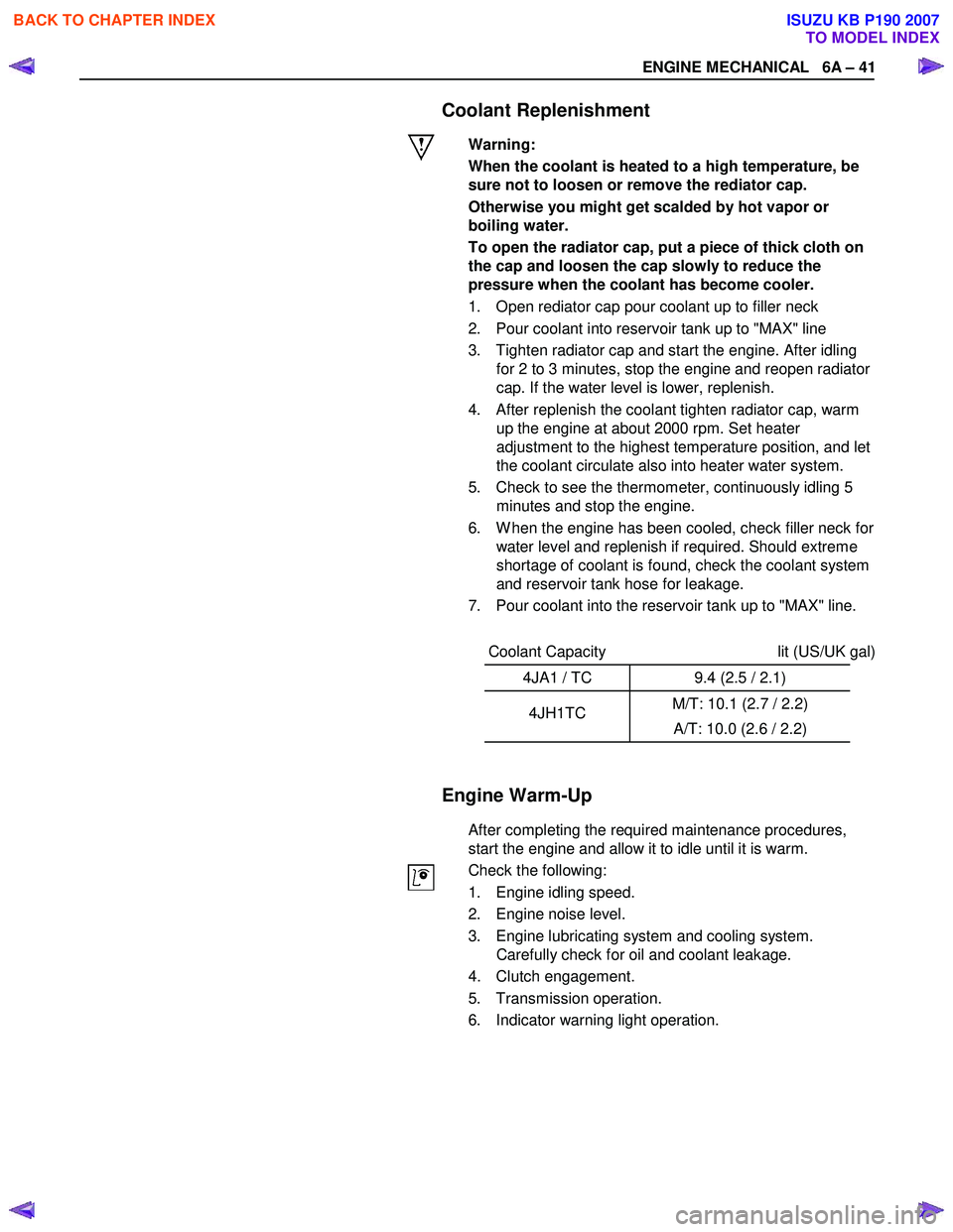
Coolant Replenishment
Warning:
When the coolant is heated to a high temperature, be
sure not to loosen or remove the rediator cap.
Otherwise you might get scalded by hot vapor or
boiling water.
To open the radiator cap, put a piece of thick cloth on
the cap and loosen the cap slowly to reduce the
pressure when the coolant has become cooler.
1. Open rediator cap pour coolant up to filler neck
2. Pour coolant into reservoir tank up to "MAX" line
3. Tighten radiator cap and start the engine. After idling for 2 to 3 minutes, stop the engine and reopen radiator
cap. If the water level is lower, replenish.
4. After replenish the coolant tighten radiator cap, warm up the engine at about 2000 rpm. Set heater
adjustment to the highest temperature position, and let
the coolant circulate also into heater water system.
5. Check to see the thermometer, continuously idling 5 minutes and stop the engine.
6. W hen the engine has been cooled, check filler neck for water level and replenish if required. Should extreme
shortage of coolant is found, check the coolant system
and reservoir tank hose for leakage.
7. Pour coolant into the reservoir tank up to "MAX" line.
Coolant Capacity lit (US/UK gal)
4JA1 / TC 9.4 (2.5 / 2.1)
4JH1TC M/T: 10.1 (2.7 / 2.2)
A/T: 10.0 (2.6 / 2.2)
Engine Warm-Up
After completing the required maintenance procedures,
start the engine and allow it to idle until it is warm.
Check the following:
1. Engine idling speed.
2. Engine noise level.
3. Engine lubricating system and cooling system. Carefully check for oil and coolant leakage.
4. Clutch engagement.
5. Transmission operation.
6. Indicator warning light operation.
BACK TO CHAPTER INDEX
TO MODEL INDEX
ISUZU KB P190 2007
Page 951 of 6020
ENGINE COOLING 6B – 7
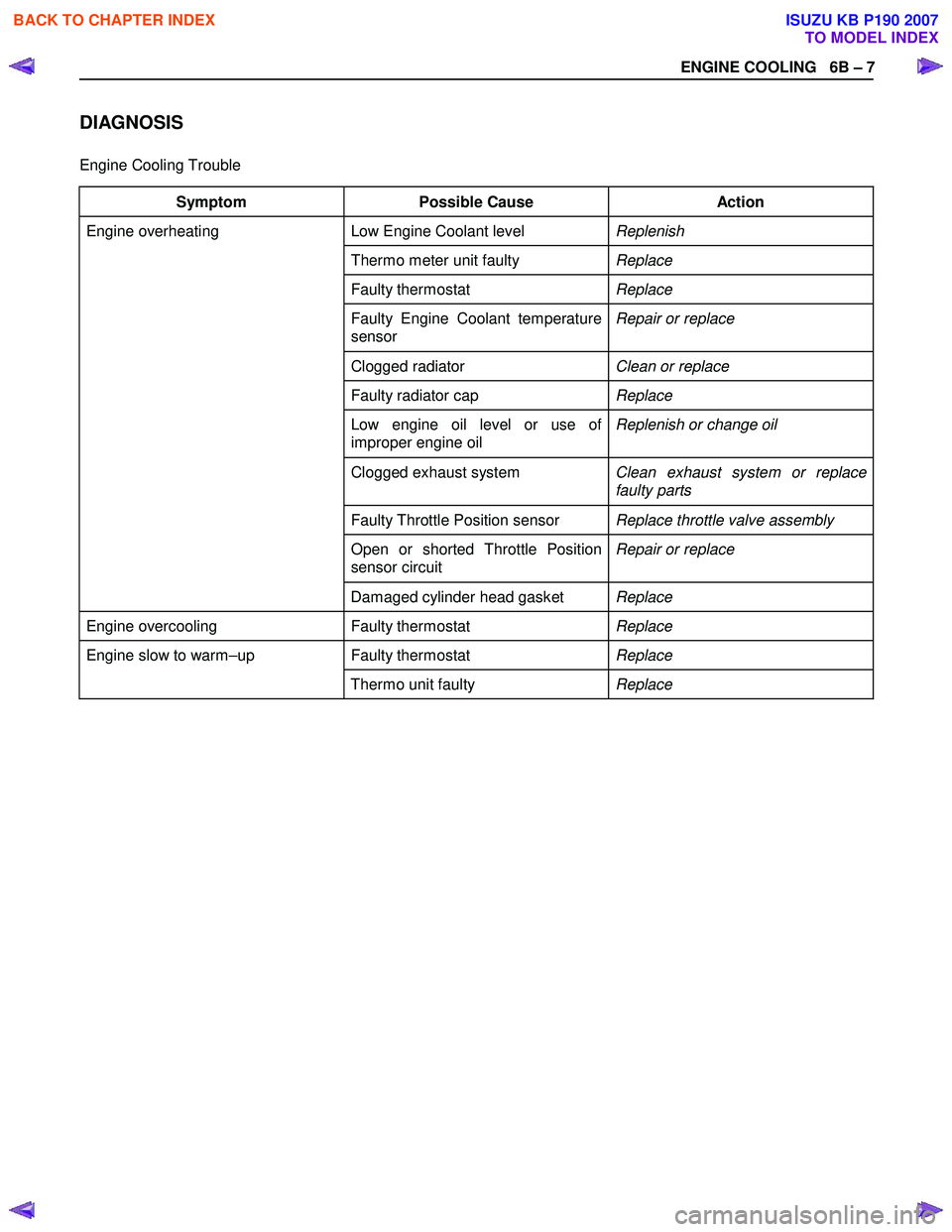
DIAGNOSIS
Engine Cooling Trouble
Symptom Possible Cause Action
Low Engine Coolant level Replenish
Thermo meter unit faulty Replace
Faulty thermostat Replace
Faulty Engine Coolant temperature
sensor Repair or replace
Clogged radiator
Clean or replace
Faulty radiator cap Replace
Low engine oil level or use of
improper engine oil Replenish or change oil
Clogged exhaust system
Clean exhaust system or replace
faulty parts
Faulty Throttle Position sensor Replace throttle valve assembly
Open or shorted Throttle Position
sensor circuit Repair or replace
Engine overheating
Damaged cylinder head gasket Replace
Engine overcooling Faulty thermostat Replace
Faulty thermostat Replace Engine slow to warm–up
Thermo unit faulty Replace
BACK TO CHAPTER INDEX
TO MODEL INDEX
ISUZU KB P190 2007
Page 952 of 6020
6B – 8 ENGINE COOLING
Draining and Refilling Cooling System
Before draining the cooling system, inspect the system and
perform any necessary service to ensure that it is clean, does
not leak and is in proper working order. The engine coolant
(EC) level should be between the “MIN" and “MAX" lines o
f
reserve tank when the engine is cold. If low, check for leakage
and add EC up to the “MAX" line.
There should not be any excessive deposit of rust or scales
around the radiator cap or radiator filler hole, and the EC
should also be free from oil.
Replace the EC if excessively dirty.
P1010064
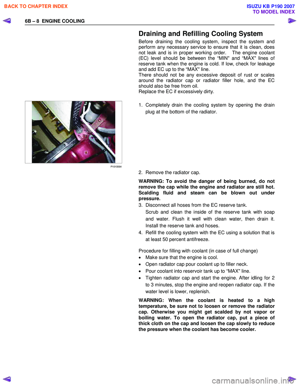
1. Completely drain the cooling system by opening the drain
plug at the bottom of the radiator.
2. Remove the radiator cap.
WARNING: To avoid the danger of being burned, do not
remove the cap while the engine and radiator are still hot.
Scalding fluid and steam can be blown out unde
r
pressure.
3. Disconnect all hoses from the EC reserve tank.
Scrub and clean the inside of the reserve tank with soap and water. Flush it well with clean water, then drain it.
Install the reserve tank and hoses.
4. Refill the cooling system with the EC using a solution that is at least 50 percent antifreeze.
Procedure for filling with coolant (in case of full change)
• Make sure that the engine is cool.
• Open radiator cap pour coolant up to filler neck.
• Pour coolant into reservoir tank up to “MAX" line.
• Tighten radiator cap and start the engine. After idling for 2
to 3 minutes, stop the engine and reopen radiator cap. If the
water level is lower, replenish.
WARNING: When the coolant is heated to a high
temperature, be sure not to loosen or remove the radiato
r
cap. Otherwise you might get scalded by not vapor or
boiling water. To open the radiator cap, put a piece of
thick cloth on the cap and loosen the cap slowly to reduce
the pressure when the coolant has become cooler.
BACK TO CHAPTER INDEX
TO MODEL INDEX
ISUZU KB P190 2007
Page 953 of 6020
ENGINE COOLING 6B – 9
• After tightening radiator cap, warm up the engine at about
2000 rpm. Set heater adjustment to the highest temperature
position, and let the coolant circulate also into heater wate
r
system.
• Check to see the thermostat has opened through the
needle position of water thermometer, conduct a 5–minute
idling again and stop the engine.
• W hen the engine has been cooled, check filler neck fo
r
water level and replenish if required. Should extreme
shortage of coolant is found, check the cooling system and
reservoir tank hose for leakage.
• Pour coolant into the reservoir tank up to “MAX" line.
BACK TO CHAPTER INDEX
TO MODEL INDEX
ISUZU KB P190 2007
Page 1038 of 6020
6E-4 Engine Control System (4JH1)
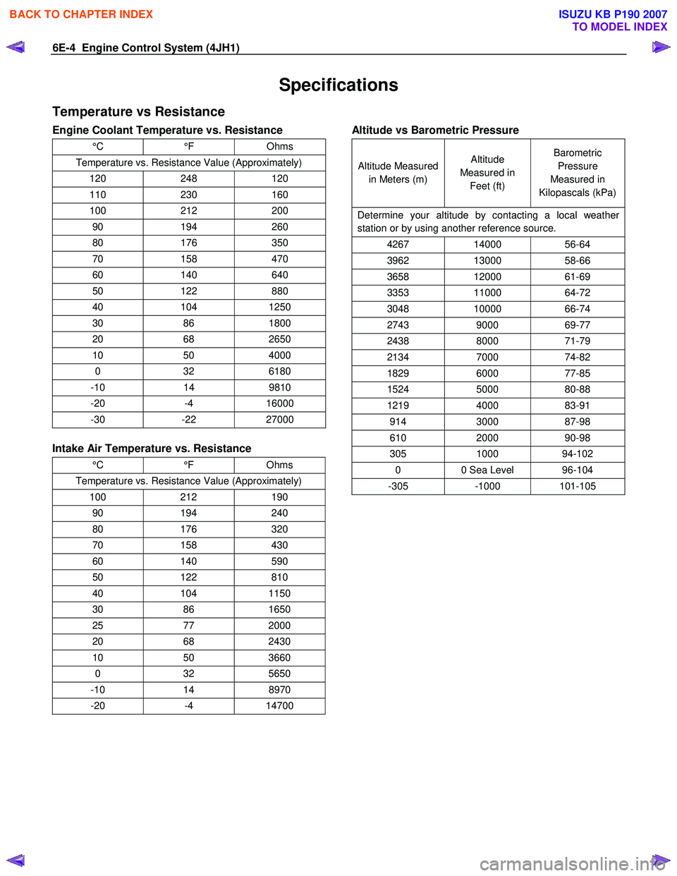
Specifications
Temperature vs Resistance
Engine Coolant Temperature vs. Resistance
°C °F Ohms
Temperature vs. Resistance Value (Approximately)
120 248 120
110 230 160
100 212 200
90 194 260
80 176 350
70 158 470
60 140 640
50 122 880
40 104 1250
30 86 1800
20 68 2650
10 50 4000
0 32 6180
-10 14 9810
-20 -4 16000
-30 -22 27000
Intake Air Temperature vs. Resistance
°C °F Ohms
Temperature vs. Resistance Value (Approximately)
100 212 190
90 194 240
80 176 320
70 158 430
60 140 590
50 122 810
40 104 1150
30 86 1650
25 77 2000
20 68 2430
10 50 3660
0 32 5650
-10 14 8970
-20 -4 14700
Altitude vs Barometric Pressure
Altitude Measured
in Meters (m) Altitude
Measured in Feet (ft) Barometric
Pressure
Measured in
Kilopascals (kPa)
Determine your altitude by contacting a local weather
station or by using another reference source.
4267 14000 56-64
3962 13000 58-66
3658 12000 61-69
3353 11000 64-72
3048 10000 66-74
2743 9000 69-77
2438 8000 71-79
2134 7000 74-82
1829 6000 77-85
1524 5000 80-88
1219 4000 83-91
914 3000 87-98
610 2000 90-98
305 1000 94-102
0 0 Sea Level 96-104
-305 -1000 101-105
BACK TO CHAPTER INDEX
TO MODEL INDEX
ISUZU KB P190 2007
Page 1070 of 6020
6E-36 Engine Control System (4JH1)
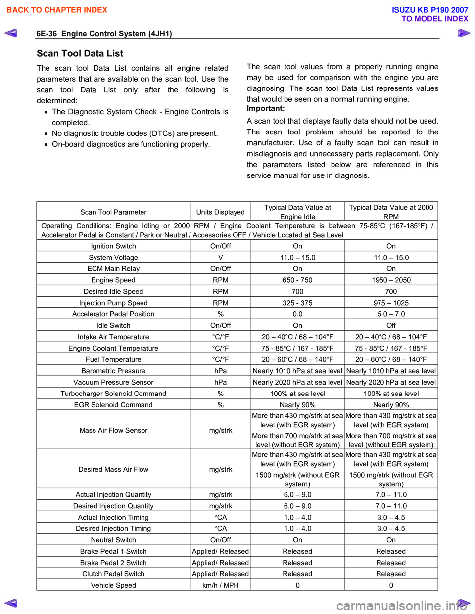
Scan Tool Data List
The scan tool Data List contains all engine related
parameters that are available on the scan tool. Use the
scan tool Data List only after the following is
determined: • The Diagnostic System Check - Engine Controls is
completed.
• No diagnostic trouble codes (DTCs) are present.
• On-board diagnostics are functioning properly.
The scan tool values from a properly running engine
may be used for comparison with the engine you are
diagnosing. The scan tool Data List represents values
that would be seen on a normal running engine.
Important:
A scan tool that displays faulty data should not be used.
The scan tool problem should be reported to the
manufacturer. Use of a faulty scan tool can result in
misdiagnosis and unnecessary parts replacement. Onl
y
the parameters listed below are referenced in this
service manual for use in diagnosis.
Scan Tool Parameter Units DisplayedTypical Data Value at
Engine Idle
Typical Data Value at 2000
RPM
Operating Conditions: Engine Idling or 2000 RPM / Engine Coolant Temperature is between 75-85 °C (167-185 °F) /
Accelerator Pedal is Constant / Park or Neutral / Accessories OFF / Vehicle Located at Sea Level
Ignition Switch On/Off On On
System Voltage V 11.0 – 15.0 11.0 – 15.0
ECM Main Relay On/Off On On
Engine Speed RPM 650 - 750 1950 – 2050
Desired Idle Speed RPM 700 700
Injection Pump Speed RPM 325 - 375 975 – 1025
Accelerator Pedal Position % 0.0 5.0 – 7.0
Idle Switch On/Off On Off
Intake Air Temperature °C/°F 20 – 40°C / 68 – 104°F 20 – 40°C / 68 – 104°F
Engine Coolant Temperature °C/°F 75 - 85 °C / 167 - 185 °F 75 - 85 °C / 167 - 185 °F
Fuel Temperature °C/°F 20 – 60°C / 68 – 140°F 20 – 60°C / 68 – 140°F
Barometric Pressure hPa Nearly 1010 hPa at sea level Nearly 1010 hPa at sea level
Vacuum Pressure Sensor hPa Nearly 2020 hPa at sea level Nearly 2020 hPa at sea level
Turbocharger Solenoid Command % 100% at sea level 100% at sea level
EGR Solenoid Command % Nearly 90% Nearly 90%
Mass Air Flow Sensor mg/strk
More than 430 mg/strk at sea
level (with EGR system)
More than 700 mg/strk at sea
level (without EGR system)
More than 430 mg/strk at sea
level (with EGR system)
More than 700 mg/strk at sea
level (without EGR system)
Desired Mass Air Flow mg/strk
More than 430 mg/strk at sea
level (with EGR system)
1500 mg/strk (without EGR
system)
More than 430 mg/strk at sea
level (with EGR system)
1500 mg/strk (without EGR
system)
Actual Injection Quantity mg/strk 6.0 – 9.0 7.0 – 11.0
Desired Injection Quantity mg/strk 6.0 – 9.0 7.0 – 11.0
Actual Injection Timing °CA 1.0 – 4.0 3.0 – 4.5
Desired Injection Timing °CA 1.0 – 4.0 3.0 – 4.5
Neutral Switch On/Off On On
Brake Pedal 1 Switch Applied/ ReleasedReleased Released
Brake Pedal 2 Switch Applied/ ReleasedReleased Released
Clutch Pedal Switch Applied/ ReleasedReleased Released
Vehicle Speed km/h / MPH 0 0
BACK TO CHAPTER INDEX
TO MODEL INDEX
ISUZU KB P190 2007
Page 1124 of 6020

6E-90 Engine Control System (4JH1)
DTC P0115 (Symptom Code 1) (Flash Code 14)
Circuit Description
The engine coolant temperature (ECT) sensor is
installed to the thermostat housing. The ECT sensor is
a variable resistor. The ECT sensor has a signal circuit
and a low reference circuit. The ECT sensor measures
the temperature of the engine coolant. The engine
control module (ECM) supplies 5 volts to the ECT signal
circuit and a ground for the ECT low reference circuit.
W hen the ECT sensor is cold, the sensor resistance is
high. W hen the engine coolant temperature increases,
the sensor resistance decreases. W ith high senso
r
resistance, the ECM detects a high voltage on the ECT
signal circuit. W ith lower sensor resistance, the ECM
detects a lower voltage on the ECT signal circuit. If the
ECM detects an excessively high ECT signal voltage,
this DTC will set.
Condition for Running the DTC
• The ignition switch is ON.
Condition for Setting the DTC
• The ECM detects that the ECT sensor signal
voltage is more than 4.7 volts for 3 seconds.
Action Taken When the DTC Sets
• The ECM illuminates the malfunction indicato
r
lamp (MIL) when the diagnostic runs and fails.
• The ECM uses an ECT substitution of fuel
temperature for engine control.
•
The ECM uses an ECT substitution of 60 °C
(120 °F) for injection timing control.
• The ECM uses an ECT substitution of -15 °C (5 °F)
for glow control.
Condition for Clearing the MIL/DTC
• The ECM turns OFF the MIL when the diagnostic
runs and does not fail.
• A history DTC clears after 40 consecutive driving
cycles without a fault. Or clear with the scan tool.
Diagnostic Aids
• If an intermittent condition is suspected, refer to
Intermittent Conditions in this section.
•
After starting the engine, the ECT should rise
steadily to about 80°C – 85°C (176°F – 185°F)
then stabilize when the thermostat opens.
• Use the Temperature vs. Resistance table to test
the ECT sensor at various temperature levels to
evaluate the possibility of a skewed sensor.
A
skewed sensor could result in poor driveabilit
y
concerns.
DTC P0115 (Symptom Code 1) (Flash Code 14)
Schematic Reference: Engine Controls Schematics
Connector End View Reference: Engine Controls
Connector End Views or Engine Control Module (ECM)
Connector End Views
Step Action Value(s) Yes No
1 Did you perform the Diagnostic System Check-
Engine Controls?
Go to Step 2 Go to Diagnostic
System Check-
Engine Controls
2 1. Install the scan tool. 2. Turn ON the ignition, with the engine OFF.
3. Observe the Engine Coolant Temperature (ECT) parameter with the scan tool.
Is the ECT parameter less than the specified value? -35°C (-31°F)
Go to Step 3 Go to Diagnostic
Aids
3 1. Turn OFF the ignition. 2. Disconnect the ECT sensor harness connector.
3. Connect a DMM between the signal circuit of the ECT sensor harness (pin 1 of E-41 connector)
and a known good ground.
4. Turn ON the ignition, with the engine OFF.
Is the DMM voltage more than the specified value? 5.5 volts
Go to Step 4 Go to Step 5
4 Important: The ECT sensor may be damaged if the
sensor signal circuit is shorted to a voltage source.
1. Test the signal circuit between the engine control module (ECM) (pin 89 of C-57 connector) and
the ECT sensor (pin 1 of E-41 connector) for a
short to battery or ignition voltage.
2. Repair the circuit(s) as necessary.
Did you find and correct the condition?
Go to Step 14 Go to Step 13
BACK TO CHAPTER INDEX
TO MODEL INDEX
ISUZU KB P190 2007