refrigerant type ISUZU KB P190 2007 Workshop Repair Manual
[x] Cancel search | Manufacturer: ISUZU, Model Year: 2007, Model line: KB P190, Model: ISUZU KB P190 2007Pages: 6020, PDF Size: 70.23 MB
Page 56 of 6020

1-22 HEATER AND AIR CONDITIONING
RECEIVER/DRIER
Capacity cc (cu in)
kPa (kg/cm
2/psi)
kPa (kg/cm2/psi)
kPa (kg/cm
2/psi)
kPa (kg/cm2/psi) 250 (15.3)
Assembly includes sight glass and pressure sensitive device
(Dual pressure switch) • Low pressure control
OFF: 177 ±26 (1.8 ±0.25/26 ±4)
ON: 186 ±30 (1.9 ±0.3/27 ±4)
• High pressure control
OFF: 2746 ±196 (28 ±2/398 ±28)
ON: 588 ±196 (6 ±2/85 ±28)
kPa (kg/cm
2/psi)
kPa (kg/cm2/psi)
kPa (kg/cm
2/psi)
kPa (kg/cm2/psi)
kPa (kg/cm
2/psi)
kPa (kg/cm2/psi)
ELECTRIC FAN
Fan Dia
Motor Power (w)
REFRIGERANT
Type
Capacity kg (lbs)
IDLE SPEED-UP CONTROL
(Triple pressure switch) • Low pressure control
OFF: 177 ±26 (1.8 ±0.25/26 ±4)
ON: 186 ±30 (1.9 ±0.3/27 ±4)
• Medium pressure control
OFF: 1128 ±118 (11.5 ±1.2/164 ±17)
ON: 1521 ±88 (15.5 ±0.9/220 ±13)
• High pressure control
OFF: 2746 ±196 (28 ±2/398 ±28)
ON: 588 ±196 (6 ±2/85 ±28)
∅250
90
HFC-134a
• 4JA1-T, 4JH1-TC, C24SE
0.72 (1.59)
• 4JJ1-TC (Standard Output),
4JJ1-TC (High Output), 4JK1-TC (High Output)
0.65 (1.43)
Idle speed controlled by solenoid switch (4JA1-T only)
BACK TO CHAPTER INDEX
TO MODEL INDEX
ISUZU KB P190 2007
Page 86 of 6020

1-52 HEATER AND AIR CONDITIONING
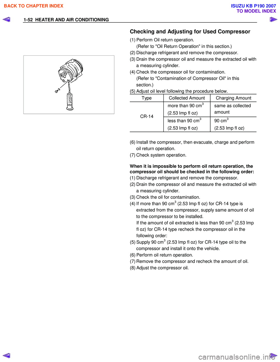
Checking and Adjusting for Used Compressor
(1) Perform Oil return operation.
(Refer to "Oil Return Operation" in this section.)
(2) Discharge refrigerant and remove the compressor.
(3) Drain the compressor oil and measure the extracted oil with
a measuring cylinder.
(4) Check the compressor oil for contamination.
(Refer to "Contamination of Compressor Oil" in this section.)
(5) Adjust oil level following the procedure below.
Type Collected Amount Charging Amount
more than 90 cm3
(2.53 lmp fl oz) same as collected
amount
less than 90 cm3
(2.53 lmp fl oz) 90 cm3
(2.53 lmp fl oz) CR-14
(6) Install the compressor, then evacuate, charge and perform
oil return operation.
(7) Check system operation.
When it is impossible to perform oil return operation, the
compressor oil should be checked in the following order:
(1) Discharge refrigerant and remove the compressor.
(2) Drain the compressor oil and measure the extracted oil with a measuring cylinder.
(3) Check the oil for contamination.
(4) If more than 90 cm
3 (2.53 lmp fl oz) for CR-14 type is
extracted from the compressor, supply same amount of oil
to the compressor to be installed.
If the amount of oil extracted is less than 90 cm
3 (2.53 lmp
fl oz) for CR-14 type recheck the compressor oil in the
following order:
(5) Supply 90 cm
3 (2.53 lmp fl oz) for CR-14 type oil to the
compressor and install it onto the vehicle.
(6) Perform oil return operation.
(7) Remove the compressor and recheck the amount of oil.
(8) Adjust the compressor oil.
BACK TO CHAPTER INDEX
TO MODEL INDEX
ISUZU KB P190 2007
Page 3423 of 6020

Engine Management – V6 – Diagnostics Page 6C1-2–145
An A/C refrigerant pressure sensor circuit DTC sets if the ECM detects the A/C pressure sensor signal is not within the
specified range for 3 seconds.
Conditions for Running the DTC
DTC P0532 and P0533 run continuously when the engine is running or when the A/C is switched on.
Conditions for Setting the DTC
DTC P0532
The A/C refrigerant pressure signal voltage is less than 0.2 V for longer than 3 seconds.
DTC P0533
The A/C refrigerant pressure signal voltage is greater than 4.9 V for longer than 3 seconds.
Conditions for Clearing the DTC
The A/C refrigerant pressure sensor circuit DTCs are Type C DTCs. Refer to 1.4 Diagnostic Trouble Codes in this
Section, for action taken when Type C DTC sets and conditions for clearing Type C DTCs.
Additional Information
• Refer to 6C1-1 Engine Management – V6 – General Information for details of the A/C Refrigerant Pressure Sensor
operation.
• For an intermittent fault condition, refer to 5.2 Intermittent Fault Conditions in this Section.
• The A/C refrigerant pressure sensor circuit diagnostic table is developed with the assumption the A/C refrigerant
system is functioning correctly. Therefore, rectify any A/C refrigerant system fault conditions before proceeding
with this diagnostic procedure.
− An A/C refrigerant low-pressure fault condition may cause DTC P0532 to set.
− An A/C refrigerant high-pressure fault condition may cause DTC P0533 to set.
• Since fault condition in a wiring connector may trigger DTCs, always test the connectors related to this diagnostic
procedure for shorted terminals or poor wiring connection before replacing any component. Refer to 8A Electrical -
Body and Chassis for information on electrical fault diagnosis.
• To assist diagnosis, refer to 3 W iring Diagrams and Connector Charts in this Section, for the system wiring
diagram and connector charts.
Test Description
The following numbers refer to the step numbers in the diagnostic table:
2 Determines if there is an A/C refrigerant system fault condition.
6 Measures the integrity of the A/C Refrigerant Pressure Sensor low reference circuit. Removal of the ECM Fuse 29 enables the ECM to power down completely prior to the test procedure.
DTC P0532 or P0533 Diagnostic Table
Step Action Yes No
1 Has the Diagnostic System Check been performed?
Go to Step 2 Refer to
4.4 Diagnostic
System Check in this Section
2 Test the A/C refrigerant system. Refer to 2A Heater and Air-
conditioning.
W as any fault found and rectified? Go to Step 12 Go to Step 3
BACK TO CHAPTER INDEX
TO MODEL INDEX
ISUZU KB P190 2007