rear combination ISUZU KB P190 2007 Workshop Repair Manual
[x] Cancel search | Manufacturer: ISUZU, Model Year: 2007, Model line: KB P190, Model: ISUZU KB P190 2007Pages: 6020, PDF Size: 70.23 MB
Page 221 of 6020
2B-24 SHEET METAL
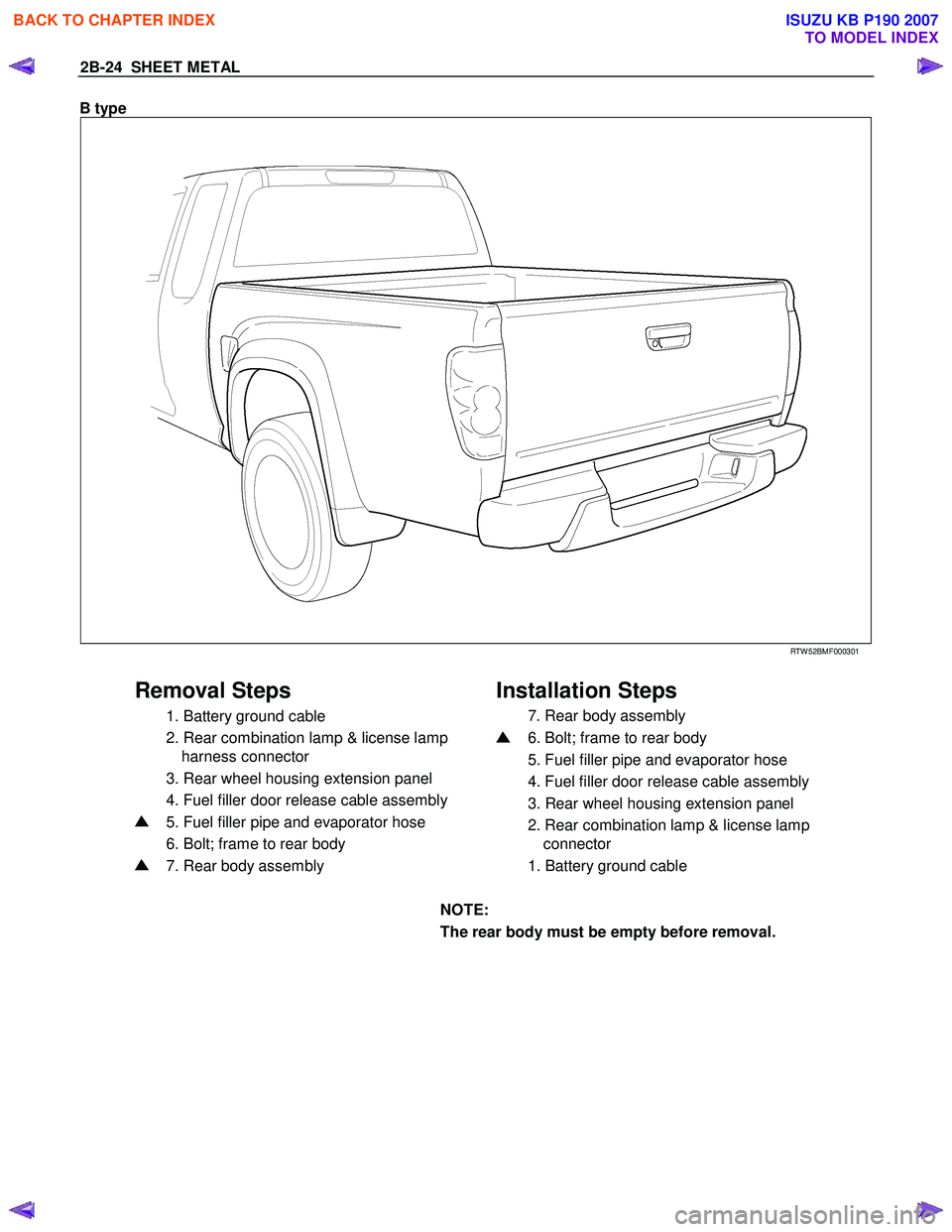
B type
RTW 52BMF000301
Removal Steps Installation Steps
1. Battery ground cable
2. Rear combination lamp & license lamp
harness connector
3. Rear wheel housing extension panel
4. Fuel filler door release cable assembly
5. Fuel filler pipe and evaporator hose
6. Bolt; frame to rear body
7. Rear body assembly
7. Rear body assembly
6. Bolt; frame to rear body
5. Fuel filler pipe and evaporator hose
4. Fuel filler door release cable assembly
3. Rear wheel housing extension panel
2. Rear combination lamp & license lamp
connector
1. Battery ground cable
NOTE:
The rear body must be empty before removal.
BACK TO CHAPTER INDEX
TO MODEL INDEX
ISUZU KB P190 2007
Page 259 of 6020
FRONT ALIGNMENT 3A-11
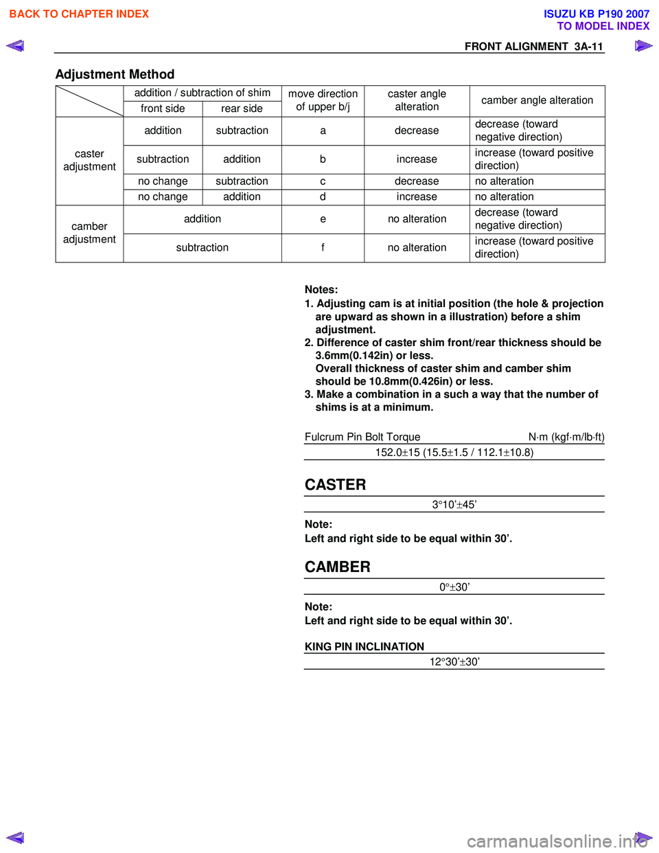
Adjustment Method
addition / subtraction of shim front side rear side move direction
of upper b/j caster angle
alteration camber angle alteration
addition subtraction a decrease decrease (toward
negative direction)
subtraction addition b increase increase (toward positive
direction)
no change subtraction c decrease no alteration
caster
adjustment
no change addition d increase no alteration
addition e no alteration decrease (toward
negative direction) camber
adjustment subtraction f no alteration increase (toward positive
direction)
Notes:
1. Adjusting cam is at initial position (the hole & projection are upward as shown in a illustration) before a shim
adjustment.
2. Difference of caster shim front/rear thickness should be 3.6mm(0.142in) or less.
Overall thickness of caster shim and camber shim
should be 10.8mm(0.426in) or less.
3. Make a combination in a such a way that the number of shims is at a minimum.
Fulcrum Pin Bolt Torque N⋅m (kgf ⋅m/lb ⋅ft)
152.0 ±15 (15.5 ±1.5 / 112.1 ±10.8)
CASTER
3 °10’ ±45’
Note:
Left and right side to be equal within 30’.
CAMBER
0 °± 30’
Note:
Left and right side to be equal within 30’.
KING PIN INCLINATION
12 °30’ ±30’
BACK TO CHAPTER INDEX
TO MODEL INDEX
ISUZU KB P190 2007
Page 465 of 6020
REAR AXLE 4B-21
Disassembly
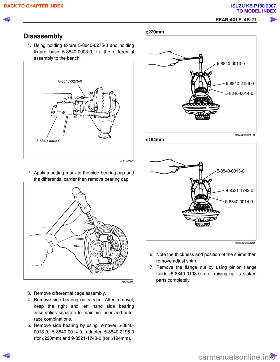
1. Using holding fixture 5-8840-0275-0 and holding
fixture base 5-8840-0003-0, fix the differential
assembly to the bench.
425L100007
2.
Apply a setting mark to the side bearing cap and
the differential carrier then remove bearing cap.
425RS009
3. Remove differential cage assembly.
4. Remove side bearing outer race. After removal,
keep the right and left hand side bearing
assemblies separate to maintain inner and oute
r
race combinations.
5. Remove side bearing by using remover 5-8840-
0013-0, 5-8840-0014-0, adapter 5-8840-2196-0
(for φ220mm) and 9-8521-1743-0 (for φ194mm).
φ
φφ
φ
220mm
RTW 54BSH000101
φ
φφ
φ
194mm
RTW 54BSH000201
6. Note the thickness and position of the shims then
remove adjust shim.
7. Remove the flange nut by using pinion flange holder 5-8840-0133-0 after raising up its staked
parts completely.
BACK TO CHAPTER INDEX
TO MODEL INDEX
ISUZU KB P190 2007
Page 597 of 6020

5A-4 BRAKE CONTROL SYSTEM
General Description
EHCU has controlled ABS (Anti-lock Brake System) and
EBD (Electronic Brake-force Distribution System). ABS
works on all four wheels. EBD system works on rear 2
wheels. A combination of wheel speed sensor and
Electronic Hydraulic Control Unit (EHCU) can determine
when a wheel is about to stop turning and adjust brake
pressure to maintain best braking. This system helps the driver maintain greater control of
the vehicle under heavy braking conditions.
Note: The Electronic Hydraulic Control Unit (EHCU)
comprises the Hydraulic Unit (H/U) and Control Unit.
This illustration is based on RHD model
RTW 75AMF001101
Legend
(1) Electronic (6) Front Left W heel Speed Sensor
(2) Hydraulic (7) Rear Right W heel Speed Sensor
(3) Hydraulic Unit (H/U) (8) Rear Left W heel Speed Sensor
(4) Control Unit (9) G sensor (4W D only)
(5) Front Right W heel Speed Sensor (10) 2-4W D Control Unit (4W D only)
BACK TO CHAPTER INDEX
TO MODEL INDEX
ISUZU KB P190 2007
Page 2452 of 6020

ENGINE EXHAUST 6F-3
W hen inspecting or replacing exhaust system components,
make sure there is adequate clearance from all points on the
underbody to prevent overheating the floor pan and possible
damage to the passenger compartment insulation and trim
materials.
Check complete exhaust system and nearby body areas and
rear compartment lid for broken, damaged, missing or
mispositioned parts, open seams, holes, loose connections or
other deterioration which could permit exhaust fumes to seep
into the rear compartment or passenger compartment. Dust or
water in the rear compartment may be an indication of a
problem in one of these areas. Any faulty areas should be
corrected immediately.
Hangers
Various types of hangers are used to support exhaust
system(s). These include conventional rubber straps, rubber
rings, and rubber blocks.
The installation of exhaust system supports is very important,
as improperly installed supports can cause annoying vibrations
which can be difficult to diagnose.
Three Way Catalytic Converter (If applicable)
The three way catalytic converter is an emission control device
added to the exhaust system to reduce pollutants from the
exhaust gas stream.
CAUTION: The catalytic converter requires the use of
unleaded fuel only.
Periodic maintenance of the exhaust system is not required. If
the vehicle is raised for other service, it is advisable to check
the condition of the complete exhaust system.
A dual bed monolith catalytic converter is used in combination
with three way catalytic converter.
Catalytic Types:
Three way (Reduction/Oxidation) catalyst
The catalyst coating on the three way (reduction) converter
contains platinum and rhodium which lowers the levels of
nitrous oxide (NOx) as well as hydrocarbons (HC) and carbon
monoxide (Co).
Gasket
The gasket must be replaced whenever a new exhaust pipe,
muffler or catalytic converter is installed.
BACK TO CHAPTER INDEX
TO MODEL INDEX
ISUZU KB P190 2007
Page 2843 of 6020
Engine Mechanical – V6 Page 6A1–66
Page 6A1–66
3 Minor Service Operations
ATTENTION
The V6 engine is a combination of numerous components, containing machined, honed, polished and lapped
surfaces manufactured on the latest, high technology production equipment. Many of the components
contain tolerances measured in thousa ndths of a millimetre. Consequently, when any e ngine component is to
be serviced, care and cleanliness are extremely important.
Prior to re-assembly of the engine, all components mu st be cleaned and inspected in accordance with the
relevant clean and inspect procedur es throughout this Section, and repl aced or repaired where required.
In addition to cleaning and inspecting components, a liberal coating of engine oil should be applied to friction
surfaces during assembly to protect and lubr icate the surfaces on initial operation.
When performing any service operation, it should be understood that correct cleaning and protection of
machined surfaces and friction areas is part of the repair procedure. This is considered standard workshop
practice, even if not specifically stated. Torque va lues must be used as specified during reassembly to
ensure correct retention of all components.
Through out this section, fastener torque wrench sp ecifications may be accompanied with the following
identification marks:
■ Fasteners must be replaced after loosening.
Fasteners either have micro encapsulated sealant a pplied or incorporate a mechanical thread lock and
should only be re-used once. If in doubt, replacement is recommended.
If one of these identification marks is present alongs ide a fastener torque wrench specification, the
recommendation regarding that fastener must be adhered to.
3.1 Engine Oil
The procedure outlined below is typically the same for both rear wheel drive and all wheel drive vehicles.
Check
The following procedure is applicable to both rear wheel and all wheel drive vehicles
1 Run the engine to bring it to normal operating temperature.
2 Park the vehicle on a level surface. A vehicle that is not level will affect the accuracy of the level reading.
3 Stop the engine and wait 5 to 10 minutes to a llow the oil to drain back into the oil pan.
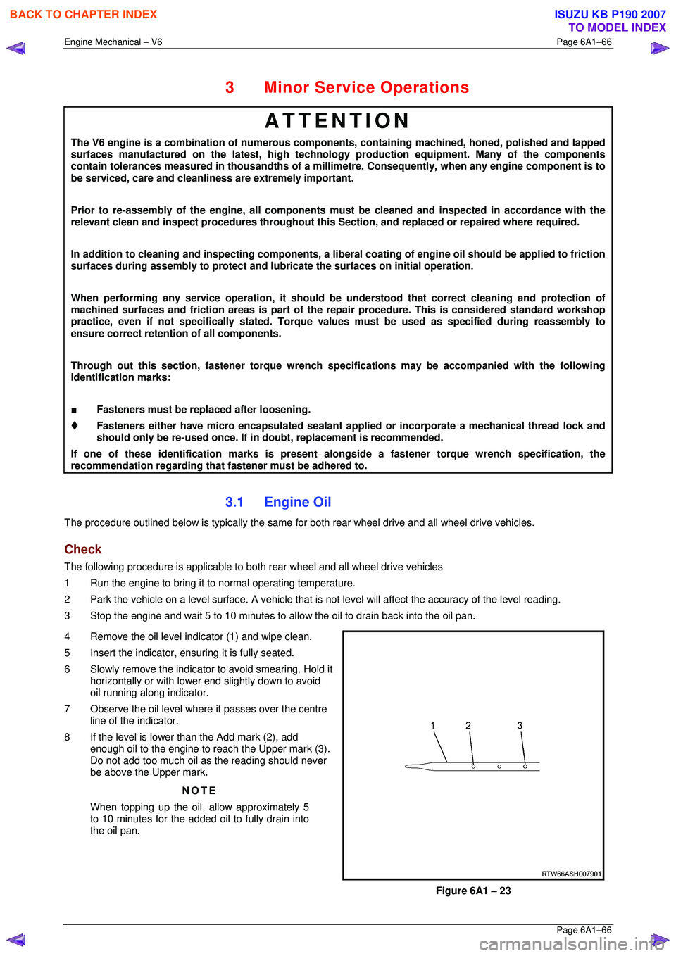
4 Remove the oil level indicator (1) and wipe clean.
5 Insert the indicator, ens uring it is fully seated.
6 Slowly remove the indicator to avoid smearing. Hold it horizontally or with lower end slightly down to avoid
oil running along indicator.
7 Observe the oil level where it passes over the centre
line of the indicator.
8 If the level is lower than the Add mark (2), add enough oil to the engine to reach the Upper mark (3).
Do not add too much oil as the reading should never
be above the Upper mark.
NOTE
When topping up the oil, allow approximately 5
to 10 minutes for the added oil to fully drain into
the oil pan.
Figure 6A1 – 23
BACK TO CHAPTER INDEX
TO MODEL INDEX
ISUZU KB P190 2007
Page 4249 of 6020

7A1-10 CONSTRUCTION AND FUNCTION
INPUT SHAFT
• The input shaft has some oil holes, through which lubricating ATF is supplied to the torque converter, the
bearings, etc.
• The input shaft is fitted to the turbine runner in the torque converter, the reverse & high clutch drum and
the rear sun gear by means of the spline. Therefore, the engine driving force received by the torque
converter is transmitted to the reverse & high clutch drum and rear sun gear.
OUTPUT SHAFT
• The output shaft has some oil holes, through which the lubricating ATF is supplied to the bearings, the
planetary gear unit, etc.
• The output shaft transmits the engine driving force from the planetary gear to the propeller shaft.
• The front internal gear is fitted with the rear carrier assembly by spline. The parking gear is also fitted by
spline. By fixing this gear mechanically, the output shaft is fixed as required when parking the vehicle.
GEAR SHIFTING MECHANISM
• The JR405E consists of two sets of planetary gears, three multiple plate clutches, two multiple plate
brakes and a one-way clutch. They are activated in different combinations in any of four forward and one
reverse gear positions.
Principle of gear shifting (Figure 12) • Planetary gears have the advantage of a compact configuration because of the way they are constructed
with a single central shaft.
• Also, unlike the manual transmission gears that require changing of the gear mesh, the gear ratio of the
planetary gears can be changed more easily by locking, releasing or rotating only some of their parts.
• A planetary gear is made up of a sun gear (1) at its center, and pinion gears (2) each of which rotates
about its own center and around the sun gear, as shown. They are all contained within the internal gear
(3).
• Also, since the pinion gears are further supported by the planetary carrier (4), they rotate as a unit in the
same direction, and at the same rate.
• As shown below, each planetary gear is constructed of three elements; a sun gear, pinion gears, an
internal gear and a planetary carrier. Gear shifting is achieved by conditioning two of the three elements,
namely the sun gear, the internal gear and planetary carrier.
• The planetary gears are locked by the clutch, brake and one-way clutch according to the gear shifting.
1. Sun Gear
2. Pinion Gear
3. Internal Gear
4. Planetary Carrier
Figure 12. Planetary Gear
BACK TO CHAPTER INDEX
TO MODEL INDEX
ISUZU KB P190 2007
Page 4917 of 6020
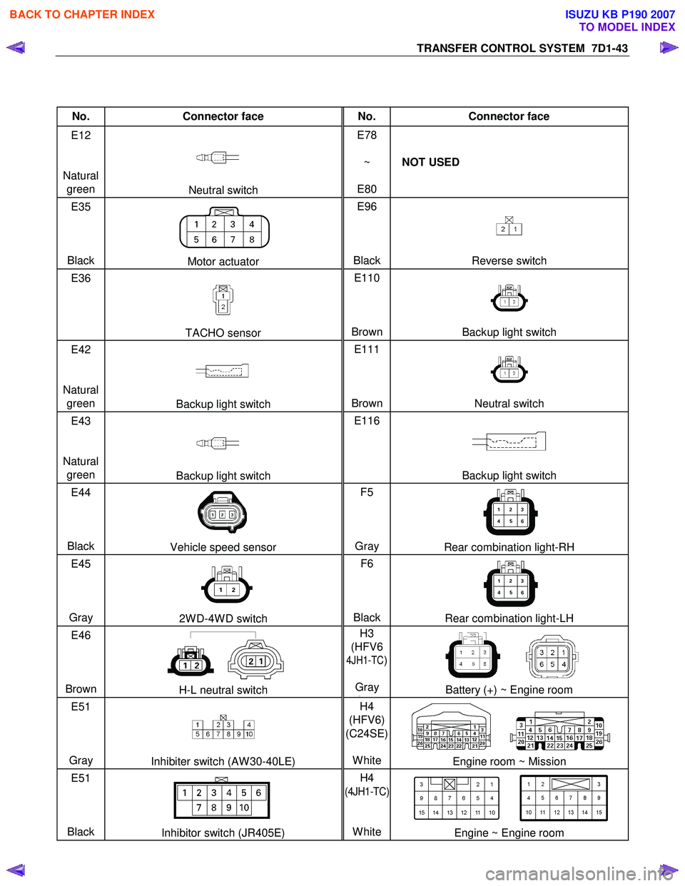
TRANSFER CONTROL SYSTEM 7D1-43
No. Connector face No. Connector face
E12
Natural green
Neutral switch E78
~
E80 NOT USED
E35
Black
Motor actuator E96
BlackReverse switch
E36
TACHO sensor E110
BrownBackup light switch
E42
Natural green
Backup light switch E111
BrownNeutral switch
E43
Natural green
Backup light switch E116
Backup light switch
E44
Black
Vehicle speed sensor F5
Gray Rear combination light-RH
E45
Gray
2W D-4W D switch F6
BlackRear combination light-LH
E46
Brown
H-L neutral switch H3
(HFV6
4JH1-TC)
Gray
GBattery (+) ~ Engine room
E51
Gray
Inhibiter switch (AW 30-40LE) H4
(HFV6)
(C24SE)
WhiteEngine room ~ Mission
E51
Black
Inhibitor switch (JR405E) H4
(4JH1-TC)
White
Engine ~ Engine room
BACK TO CHAPTER INDEX
TO MODEL INDEX
ISUZU KB P190 2007
Page 5173 of 6020

ELECTRICAL-BODY AND CHASSIS 8A-235
REMOVAL AND INSTALLATION
A Type
RTW 780SH002101
REAR COMBINATION LIGHT
Stoplight
Removal
1. Open the tail gate.
2. Remove the screws of rear combination light.
3. Remove the rear combination light assembly.
B Type
RTW 580SH000401
A Type
RTW 780SH001201
4. Turn the bulb (1) counterclockwise to remove it.
B Type
RTW 580SH000501
Installation
Follow the removal procedure in the reverse order to install the
rear combination light.
Pay close attention to the important points mentioned in the
following paragraphs.
Bulb
Be absolutely sure that each bulb is correctly installed.
This will prevent a poor contact and an open circuit.
BACK TO CHAPTER INDEX TO MODEL INDEXISUZU KB P190 2007
Page 5174 of 6020
8A-236 ELECTRICAL-BODY AND CHASSIS
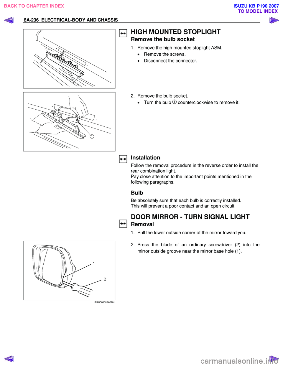
HIGH MOUNTED STOPLIGHT
Remove the bulb socket
1. Remove the high mounted stoplight ASM. • Remove the screws.
• Disconnect the connector.
2. Remove the bulb socket.
• Turn the bulb
1 counterclockwise to remove it.
Installation
Follow the removal procedure in the reverse order to install the
rear combination light.
Pay close attention to the important points mentioned in the
following paragraphs.
Bulb
Be absolutely sure that each bulb is correctly installed.
This will prevent a poor contact and an open circuit.
DOOR MIRROR - TURN SIGNAL LIGHT
Removal
1. Pull the lower outside corner of the mirror toward you.
RUW 580SH000701
2. Press the blade of an ordinary screwdriver (2) into the
mirror outside groove near the mirror base hole (1).
BACK TO CHAPTER INDEX TO MODEL INDEXISUZU KB P190 2007