ISUZU TF SERIES 2004 Workshop Manual
Manufacturer: ISUZU, Model Year: 2004, Model line: TF SERIES, Model: ISUZU TF SERIES 2004Pages: 4264, PDF Size: 72.63 MB
Page 1441 of 4264
4JA1/4JH1 ENGINE DRIVEABILITY AND EMISSIONS 6E–69
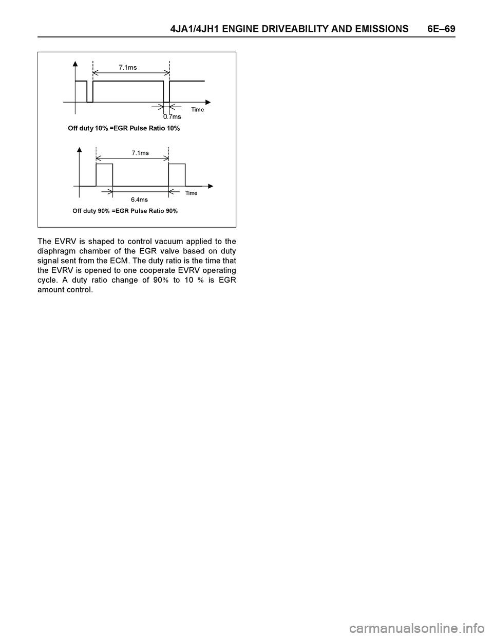
The EVRV is shaped to control vacuum applied to the
diaphragm chamber of the EGR valve based on duty
signal sent from the ECM. The duty ratio is the time that
the EVRV is opened to one cooperate EVRV operating
cycle. A duty ratio change of 90% to 10 % is EGR
amount control.
7.1m s
Time 0. 7m s Off duty 10% =EGR Pulse Ratio 10%
7.1ms
Ti m e 6.4ms Off duty 90% =EGR Pulse Ratio 90%
Page 1442 of 4264
6E–70 4JA1/4JH1 ENGINE DRIVEABILITY AND EMISSIONS
GENERAL DESCRIPTION FOR INJECTION
PUMP
Outline
Instead of the previous face cam type, the radial plunger
distributor type injection pump utilizes a cam ring to
enable fuel injection at high-pressures, marking it
suitable for small, high-speed direct injection diesel
engines. This pump was developed to provide the most
suitable fuel injection quantity and injection timing to
satisfy the demand for engine reliability, driveability, low
smoke, low noise, high output and clear ex haust
emissions.
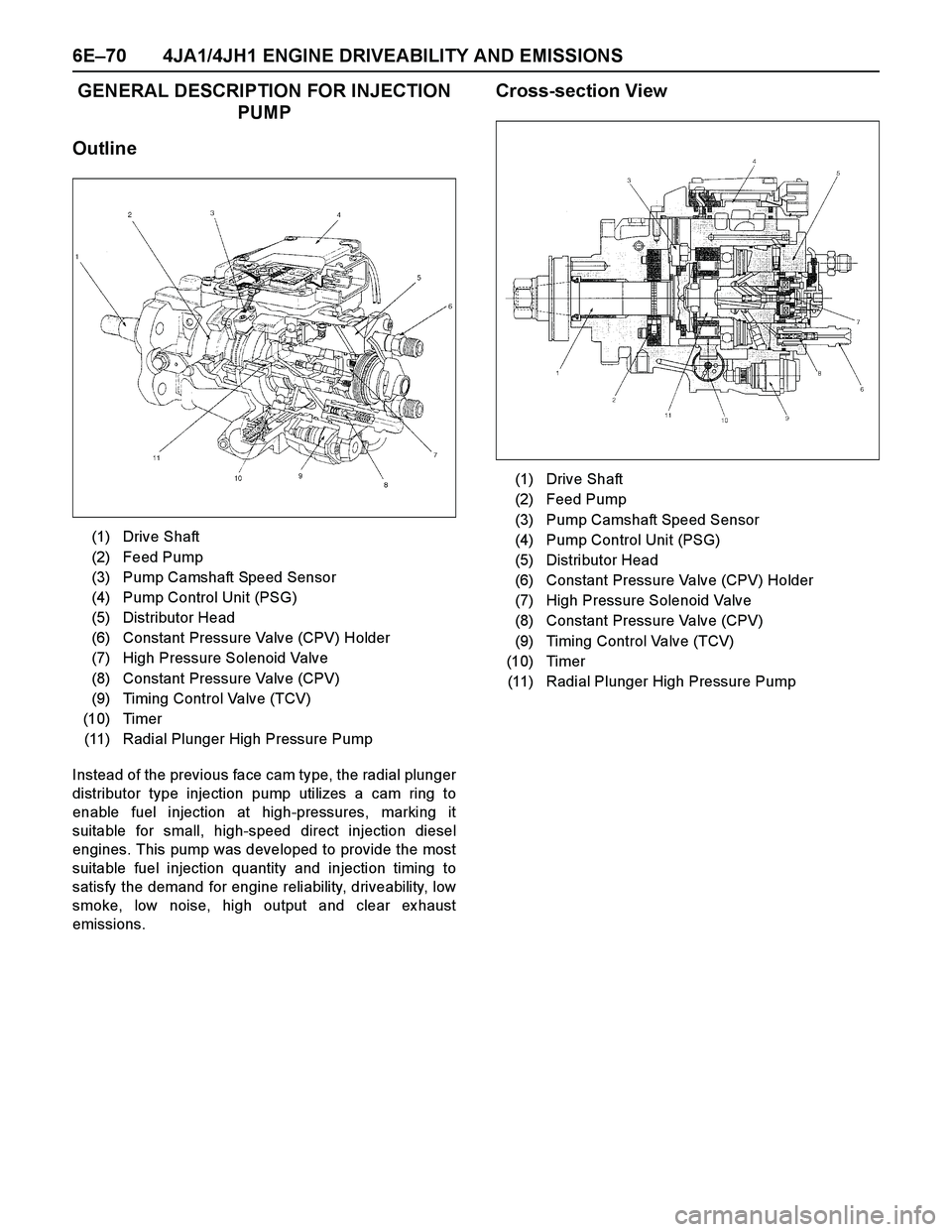
Cross-section View
(1) Drive Shaft
(2) Feed Pump
(3) Pump Camshaft Speed Sensor
(4) Pump Control Unit (PSG)
(5) Distributor Head
(6) Constant Pressure Valve (CPV) Holder
(7) High Pressure Solenoid Valve
(8) Constant Pressure Valve (CPV)
(9) Timing Control Valve (TCV)
(10) Timer
(11) Radial Plunger High Pressure Pump
(1) Drive Shaft
(2) Feed Pump
(3) Pump Camshaft Speed Sensor
(4) Pump Control Unit (PSG)
(5) Distributor Head
(6) Constant Pressure Valve (CPV) Holder
(7) High Pressure Solenoid Valve
(8) Constant Pressure Valve (CPV)
(9) Timing Control Valve (TCV)
(10) Timer
(11) Radial Plunger High Pressure Pump
Page 1443 of 4264
4JA1/4JH1 ENGINE DRIVEABILITY AND EMISSIONS 6E–71
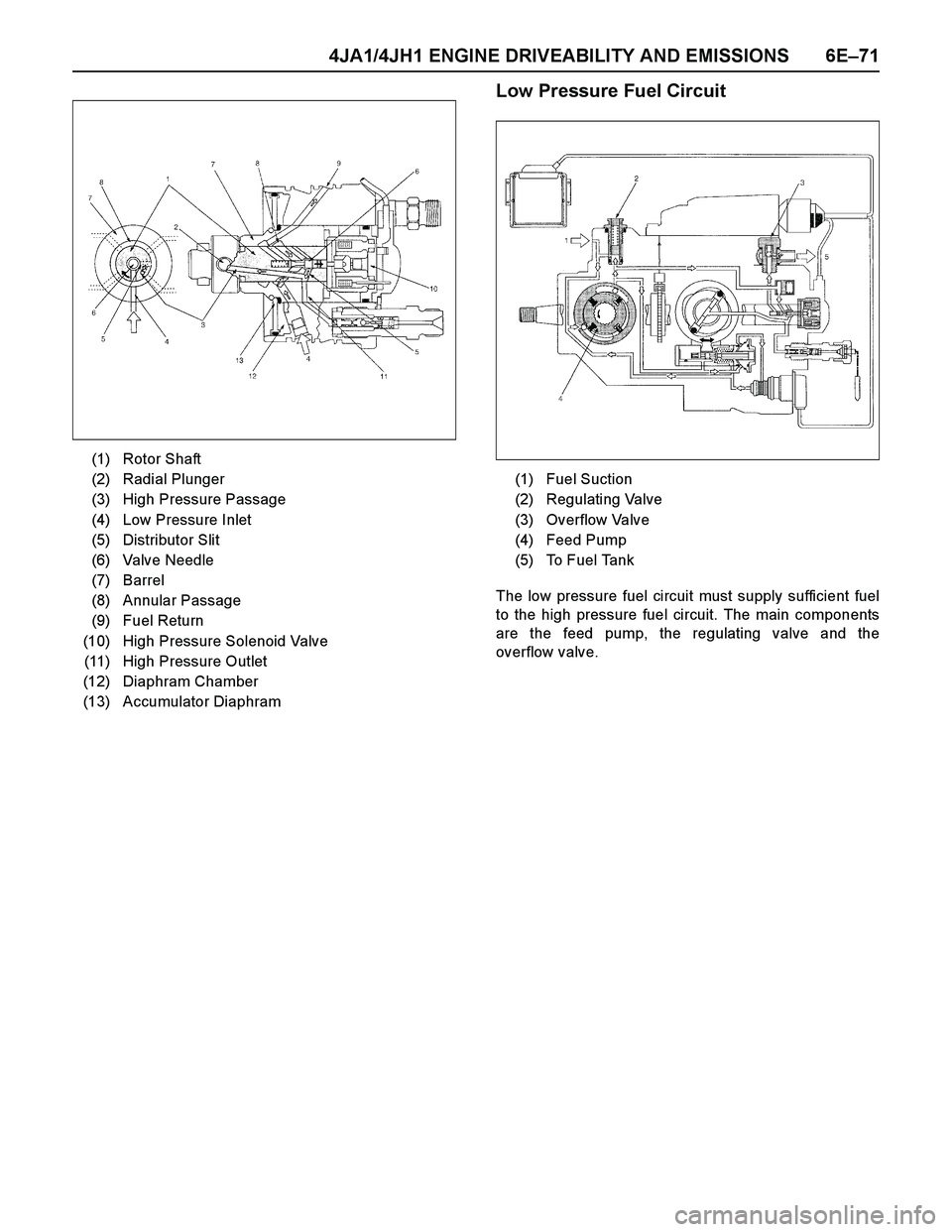
Low Pressure Fuel Circuit
The low pressure fuel circuit must supply sufficient fuel
to the high pressure fuel circuit. The main components
are the feed pump, the regulating valve and the
overflow valve. (1) Rotor Shaft
(2) Radial Plunger
(3) High Pressure Passage
(4) Low Pressure Inlet
(5) Distributor Slit
(6) Valve Needle
(7) Barrel
(8) Annular Passage
(9) Fuel Return
(10) High Pressure Solenoid Valve
(11) High Pressure Outlet
(12) Diaphram Chamber
(13) Accumulator Diaphram
(1) Fuel Suction
(2) Regulating Valve
(3) Overflow Valve
(4) Feed Pump
(5) To Fuel Tank
Page 1444 of 4264
6E–72 4JA1/4JH1 ENGINE DRIVEABILITY AND EMISSIONS
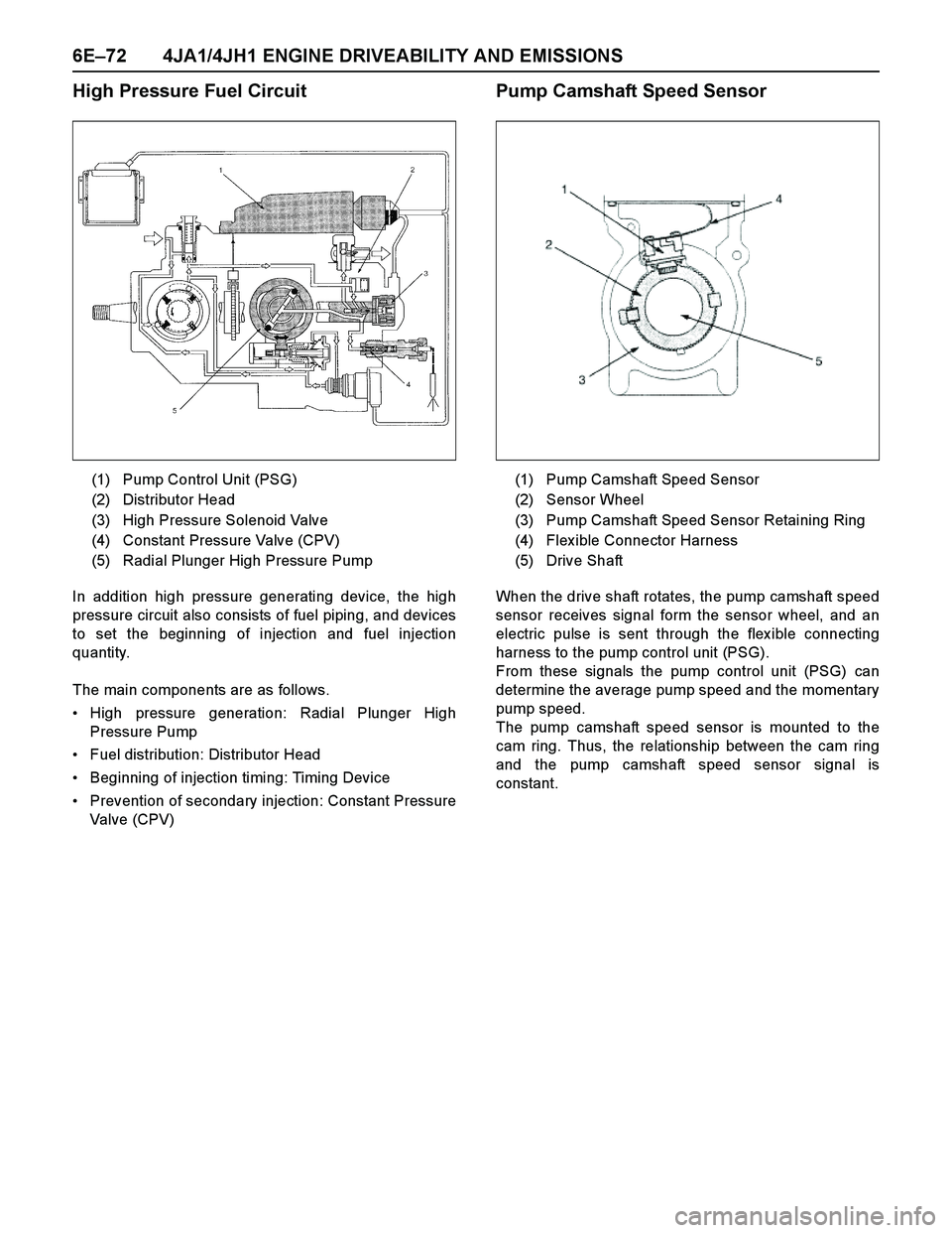
High Pressure Fuel Circuit
In addition high pressure generating device, the high
pressure circuit also consists of fuel piping, and devices
to set the beginning of injection and fuel injection
quantity.
The main components are as follows.
High pressure generation: Radial Plunger High
Pressure Pump
Fuel distribution: Distributor Head
Beginning of injection timing: Timing Device
Prevention of secondary injection: Constant Pressure
Valve (CPV)
Pump Camshaft Speed Sensor
When the drive shaft rotates, the pump camshaft speed
sensor receives signal form the sensor wheel, and an
electric pulse is sent through the flex ible connecting
harness to the pump control unit (PSG).
From these signals the pump control unit (PSG) can
determine the average pump speed and the momentary
pump speed.
The pump camshaft speed sensor is mounted to the
cam ring. Thus, the relationship between the cam ring
and the pump camshaft speed sensor signal is
constant. (1) Pump Control Unit (PSG)
(2) Distributor Head
(3) High Pressure Solenoid Valve
(4) Constant Pressure Valve (CPV)
(5) Radial Plunger High Pressure Pump
(1) Pump Camshaft Speed Sensor
(2) Sensor Wheel
(3) Pump Camshaft Speed Sensor Retaining Ring
(4) Flex ible Connector Harness
(5) Drive Shaft
Page 1445 of 4264
4JA1/4JH1 ENGINE DRIVEABILITY AND EMISSIONS 6E–73
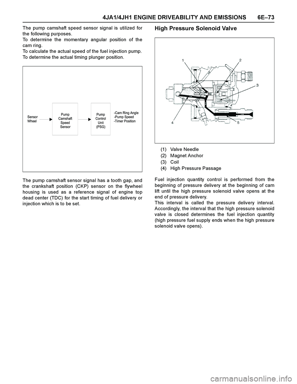
The pump camshaft speed sensor signal is utilized for
the following purposes.
To determine the momentary angular position of the
cam ring.
To calculate the actual speed of the fuel injection pump.
To determine the actual timing plunger position.
The pump camshaft sensor signal has a tooth gap, and
the crankshaft position (CKP) sensor on the flywheel
housing is used as a reference signal of engine top
dead center (TDC) for the start timing of fuel delivery or
injection which is to be set.High Pressure Solenoid Valve
Fuel injection quantity control is performed from the
beginning of pressure delivery at the beginning of cam
lift until the high pressure solenoid valve opens at the
end of pressure delivery.
This interval is called the pressure delivery interval.
Accordingly, the interval that the high pressure solenoid
valve is closed determines the fuel injection quantity
(high pressure fuel supply ends when the high pressure
solenoid valve opens).
-Cam Ring Angle
Sensor -Pump Speed
Wheel -Timer PositionPump
Control
Unit
(PSG)Pump
Camshaft
Speed
Sensor
(1) Valve Needle
(2) Magnet Anchor
(3) Coil
(4) High Pressure Passage
Page 1446 of 4264
6E–74 4JA1/4JH1 ENGINE DRIVEABILITY AND EMISSIONS
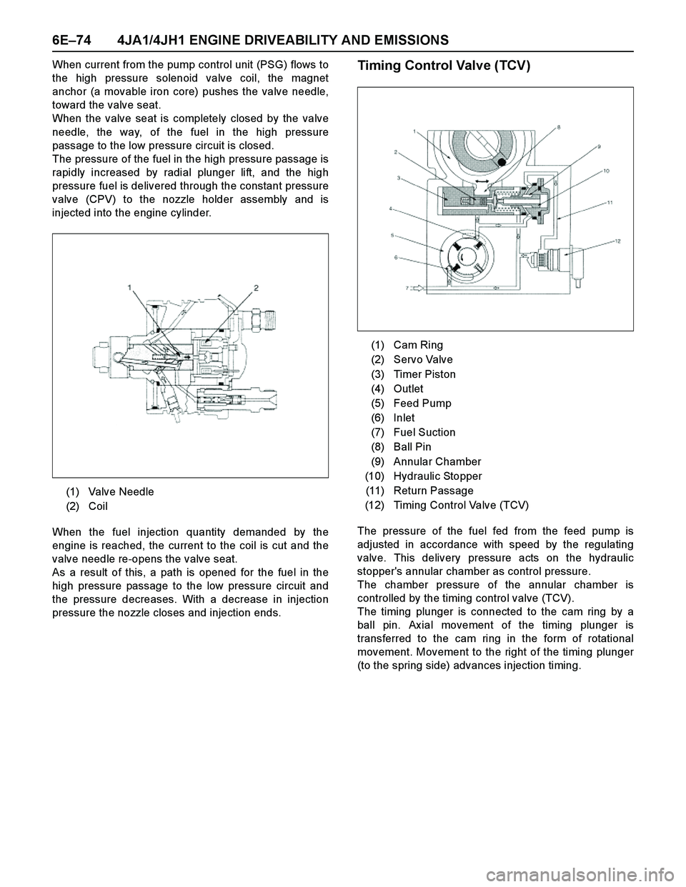
When current from the pump control unit (PSG) flows to
the high pressure solenoid valve coil, the magnet
anchor (a movable iron core) pushes the valve needle,
toward the valve seat.
When the valve seat is completely closed by the valve
needle, the way, of the fuel in the high pressure
passage to the low pressure circuit is closed.
The pressure of the fuel in the high pressure passage is
rapidly increased by radial plunger lift, and the high
pressure fuel is delivered through the constant pressure
valve (CPV) to the nozzle holder assembly and is
injected into the engine cylinder.
When the fuel injection quantity demanded by the
engine is reached, the current to the coil is cut and the
valve needle re-opens the valve seat.
As a result of this, a path is opened for the fuel in the
high pressure passage to the low pressure circuit and
the pressure decreases. With a decrease in injection
pressure the nozzle closes and injection ends.Timing Control Valve (TCV)
The pressure of the fuel fed from the feed pump is
adjusted in accordance with speed by the regulating
valve. This delivery pressure acts on the hydraulic
stopper's annular chamber as control pressure.
The chamber pressure of the annular chamber is
controlled by the timing control valve (TCV).
The timing plunger is connected to the cam ring by a
ball pin. Ax ial movement of the timing plunger is
transferred to the cam ring in the form of rotational
movement. Movement to the right of the timing plunger
(to the spring side) advances injection timing. (1) Valve Needle
(2) Coil
(1) Cam Ring
(2) Servo Valve
(3) Timer Piston
(4) Outlet
(5) Feed Pump
(6) Inlet
(7) Fuel Suction
(8) Ball Pin
(9) Annular Chamber
(10) Hydraulic Stopper
(11) Return Passage
(12) Timing Control Valve (TCV)
Page 1447 of 4264
4JA1/4JH1 ENGINE DRIVEABILITY AND EMISSIONS 6E–75
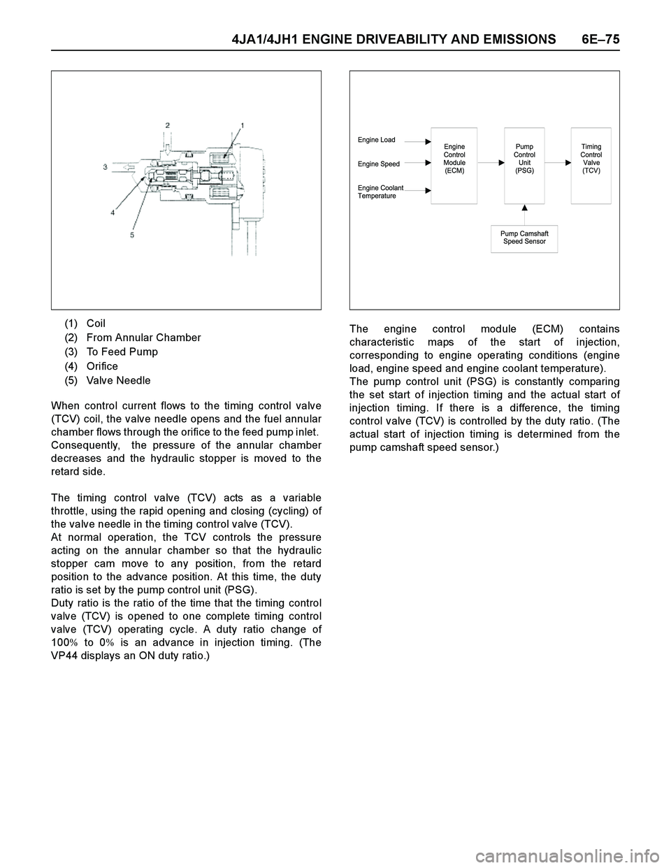
When control current flows to the timing control valve
(TCV) coil, the valve needle opens and the fuel annular
chamber flows through the orifice to the feed pump inlet.
Consequently, the pressure of the annular chamber
decreases and the hydraulic stopper is moved to the
retard side.
The timing control valve (TCV) acts as a variable
throttle, using the rapid opening and closing (cycling) of
the valve needle in the timing control valve (TCV).
At normal operation, the TCV controls the pressure
acting on the annular chamber so that the hydraulic
stopper cam move to any position, from the retard
position to the advance position. At this time, the duty
ratio is set by the pump control unit (PSG).
Duty ratio is the ratio of the time that the timing control
valve (TCV) is opened to one complete timing control
valve (TCV) operating cycle. A duty ratio change of
100% to 0% is an advance in injection timing. (The
VP44 displays an ON duty ratio.)The engine control module (ECM) contains
characteristic maps of the start of injection,
corresponding to engine operating conditions (engine
load, engine speed and engine coolant temperature).
The pump control unit (PSG) is constantly comparing
the set start of injection timing and the actual start of
injection timing. If there is a difference, the timing
control valve (TCV) is controlled by the duty ratio. (The
actual start of injection timing is determined from the
pump camshaft speed sensor.) (1) Coil
(2) From Annular Chamber
(3) To Feed Pump
(4) Orifice
(5) Valve Needle
Engine Load
Engine Speed
Engine Coolant
TemperatureEngine
Control
Module
(ECM)Pump
Control
Unit
(PSG)
Pump Camshaft
Speed Sensor
Timing
Control
Valve
(TCV)
Page 1448 of 4264

6E–76 4JA1/4JH1 ENGINE DRIVEABILITY AND EMISSIONS
ISUZU Strategy Based Diagnostics
Overview
As a retail service technician, you are part of the ISUZU
service team. The team goal is FIX IT RIGHT THE
FIRST TIME for the satisfaction of every customer. You
are a very important member of the team as you
diagnose and repair customer vehicles.You have max imum efficiency in diagnosis when you
have an effective, organized plan for your work.
Strategy Based Diagnostics (refer to Figure 1) provides
you with guidance as you create and follow a plan of
action for each specific diagnostic situation.
STRATEGY BASED DIAGNOSTICS CHART
Page 1449 of 4264
4JA1/4JH1 ENGINE DRIVEABILITY AND EMISSIONS 6E–77
Diagnostic Thought Process
As you follow a diagnostic plan, every box on the
Strategy Based Diagnostics chart requires you to use
the diagnostic thought process. This method of thinking
optimizes your diagnosis in the following ways:
Improves your understanding and definition of the
customer complaint
Saves time by avoiding testing and/or replacing good
parts
Allows you to look at the problem from different
perspectives
Guides you to determine what level of understanding
about system operation is needed:
–Owner’s manual level
–Service manual level
–In-depth (engineering) level
–Owner’s manual level
–Service manual level
–In-depth (engineering) level
1. Verify the Complaint
What you should do
To verify the customer complaint, you need to know the
correct (normal) operating behavior of the system and
verify that the customer complaint is a valid failure of the
system.
The following information will help you verify the
complaint:
WHAT the vehicle model/options are
WHAT aftermarket and dealer-installed accessories
exist
WHAT related system(s) operate properly
WHEN the problem occurs
WHERE the problem occurs
HOW the problem occurs
HOW LONG the condition has ex isted (and if the
system ever worked correctly)
HOW OFTEN the problem occurs
Whether the severity of the problem has increased,
decreased or stayed the same
What resources you should use
Whenever possible, you should use the following
resources to assist you in verifying the complaint:
Service manual Theory or Circuit Description
sections
Service manual “System Performance Check”
Owner manual operational description
Technician ex perience
Identical vehicle for comparisonCircuit testing tools
Vehicle road tests
Complaint check sheet
Contact with the customer
2. Perform Preliminary Checks
NOTE: An estimated 10 percent of successful vehicle
repairs are diagnosed with this step!
What you should do
You perform preliminary checks for several reasons:
To detect if the cause of the complaint is VISUALLY
OBVIOUS
To identify parts of the system that work correctly
To accumulate enough data to correctly and
accurately search for a ISUZU Service Bulletin on
ISUZU Web site.
The initial checks may vary depending on the
complex ity of the system and may include the following
actions:
Operate the suspect system
Make a visual inspection of harness routing and
accessible/visible power and ground circuits
Check for blown fuses
Make a visual inspection for separated connectors
Make a visual inspection of connectors (includes
checking terminals for damage and tightness)
Check for any DTCs stored by the on-board
computers
Sense unusual noises, smells, vibrations or
mov ements
Investigate the vehicle service history (call other
dealerships, if appropriate)
What resources you should use
Whenever appropriate, you should use the following
resources for assistance in performing preliminary
checks:
Tech II or other technical equipment for viewing DTCs
Service manual information:
–Component locations
–Harness routing
–Wiring schematics
–Procedures for viewing DTCs
Dealership service history file
Vehicle road test
Identical vehicle or system for comparison
Page 1450 of 4264
6E–78 4JA1/4JH1 ENGINE DRIVEABILITY AND EMISSIONS
3. Check Bulletins and
Troubleshooting Hints
NOTE: As estimated 30 percent of successful vehicle
repairs are diagnosed with this step!
What you should do
You should have enough information gained from
preliminary checks to accurately search for a bulletin
and other related service information. Some service
manual sections provide troubleshooting hints that
match symptoms with specific complaints.
What resources you should use
You should use the following resources for assistance in
checking for bulletins and troubleshooting hints:
Printed bulletins
Access ISUZU Bulletin Web site.
Videotapes
Service manual
4. Perform Service Manual
Diagnostic Checks
What you should do
The “System Checks” in most service manual sections
and in most cells of section 8A (electrical) provide you
with:
A systematic approach to narrowing down the
possible causes of a system fault
Direction to specific diagnostic procedures in the
service manual
Assistance to identify what systems work correctly
What resources you should use
Whenever possible, you should use the following
resources to perform service manual checks:
Service manual
Technical equipment (for viewing DTCs and
analyzing data)
Digital multimeter and circuit testing tools
Other tools as needed
5a and 5b. Perform Service Manual
Diagnostic Procedures
NOTE: An estimated 40 percent of successful vehicle
repairs are diagnosed with these steps!
What you should do
When directed by service manual diagnostic checks,
you must then carefully and accurately perform the
steps of diagnostic procedures to locate the fault relatedto the customer complaint.
What resources you should use
Whenever appropriate, you should use the following
resources to perform service manual diagnostic
procedures:
Service manual
Technical equipment (for analyzing diagnostic data)
Digital multimeter and circuit testing tools
Essential and special tools
5c. Technician Self Diagnoses
When there is no DTC stored and no matching
symptom for the condition identified in the service
manual, you must begin with a thorough understanding
of how the system(s) operates. Efficient use of the
service manual combined with you ex perience and a
good process of elimination will result in accurate
diagnosis of the condition.
What you should do
Step 1: Identify and understand the suspect
circuit(s)
Having completed steps 1 through 4 of the Strategy
Based Diagnostics chart, you should have enough
information to identify the system(s) or sub-system(s)
involved. Using the service manual, you should
determine and investigate the following circuit
characteristics:
Electrical:
–How is the circuit powered (power distribution
charts and/or fuse block details)?
–How is the circuit grounded (ground distribution
charts)?
–How is the circuit controlled or sensed (theory of
operation):
–If it is a switched circuit, is it normally open or
normally closed?
–Is the power switched or is the ground
switched?
–Is it a variable resistance circuit (ECT sensor
or TP sensor, for ex ample)?
–Is it a signal generating device (MAF sensor of
VSS, for example)?
–Does it rely on some mechanical/vacuum
device to operate?
Physical:
–Where are the circuit components (component
locators and wire harness routing diagrams):
–Are there areas where wires could be chafed
or pinched (brackets or frames)?
–Are there areas subjected to ex treme
temperatures?