engine ISUZU TF SERIES 2004 Workshop Manual
[x] Cancel search | Manufacturer: ISUZU, Model Year: 2004, Model line: TF SERIES, Model: ISUZU TF SERIES 2004Pages: 4264, PDF Size: 72.63 MB
Page 1237 of 4264

ENGINE MECHANICAL 6A – 97
Reassembly
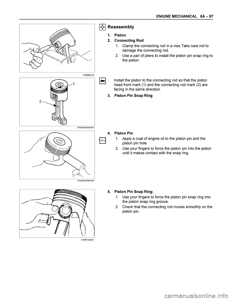
1. Piston
2. Connecting Rod
1. Clamp the connecting rod in a vise.Take care not to
damage the connecting rod.
2. Use a pair of pliers to install the piston pin snap ring to
the piston.
RTW36ASH001801
Install the piston to the connecting rod so that the piston
head front mark (1) and the connecting rod mark (2) are
facing in the same direction.
3. Piston Pin Snap Ring
RTW36ASH001901
4. Piston Pin
1. Apply a coat of engine oil to the piston pin and the
piston pin hole.
2. Use your fingers to force the piston pin into the piston
until it makes contact with the snap ring.
5. Piston Pin Snap Ring
1. Use your fingers to force the piston pin snap ring into
the piston snap ring groove.
2. Check that the connecting rod moves smoothly on the
piston pin.
F06MV015
015R100001
Page 1238 of 4264

6A – 98 ENGINE MECHANICAL
RTW36ASH002001
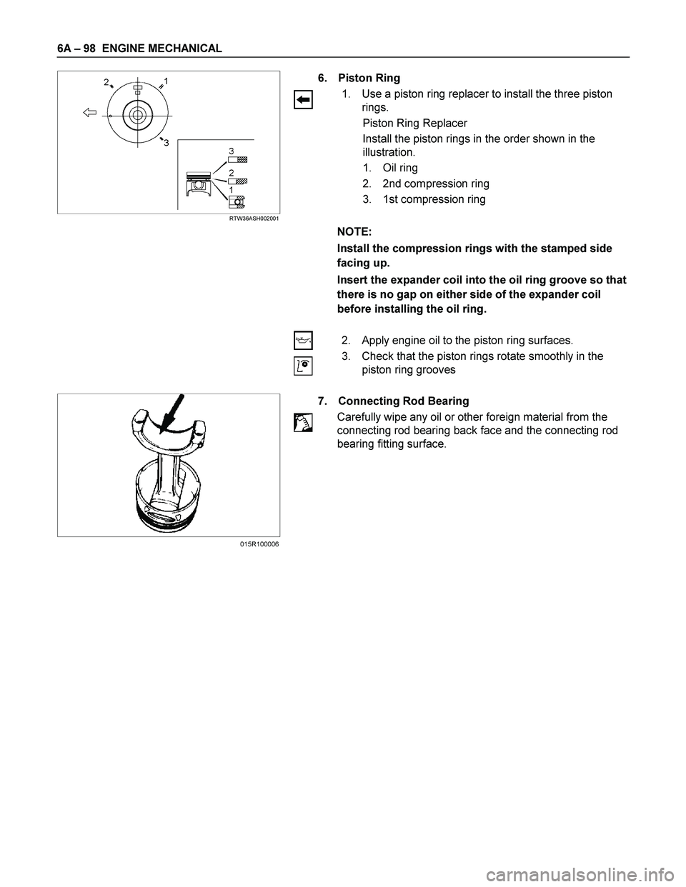
6. Piston Ring
1. Use a piston ring replacer to install the three piston
rings.
Piston Ring Replacer
Install the piston rings in the order shown in the
illustration.
1. Oil ring
2. 2nd compression ring
3. 1st compression ring
NOTE:
Install the compression rings with the stamped side
facing up.
Insert the expander coil into the oil ring groove so that
there is no gap on either side of the expander coil
before installing the oil ring.
2. Apply engine oil to the piston ring surfaces.
3. Check that the piston rings rotate smoothly in the
piston ring grooves
7. Connecting Rod Bearing
Carefully wipe any oil or other foreign material from the
connecting rod bearing back face and the connecting rod
bearing fitting surface.
015R100006
Page 1239 of 4264

ENGINE MECHANICAL 6A – 99
POSITIVE CRANKCASE VENTILATION (PCV) VALVE
RTW46AMF000101
Reassembly Steps
1. Positive Crankcase Ventilation
(PCV) Valve 5.
Fixing bolt
2.
Rubber space 6.
Oil filler cap
3.
Cylinder head insulator cover
4.
Breather pipe
Page 1240 of 4264

6A – 100 ENGINE MECHANICAL
Reassembly
1. PCV Valve
Install the PCV valve and tighten the bolts to specified
torque.
PCV Valve Bolts Torque N·m(kg·m/lb in)
2 (0.2/17)
2. Rubber Spacer
3. Cylinder Head Insulator Cover
RTW36ASH001401
4. Breather Hose
Apply LOCTITE 262 or equivalent to the new breather pipe.
Do not reuse the breather pipe.
5. Fixing Bolt
Fixing Bolt Torque N·m(kg·m/lb in)
19 (1.9/14)
6. Oil Filler Cap
010R100014
Page 1241 of 4264

ENGINE MECHANICAL 6A – 101
MAJOR COMPONENT
Reassembly Steps-1
1.
Cylinder body 10.
Camshaft timing gear
2.
Tappet 11. Piston and connecting rod with
upper bearing
3.
Crankshaft upper bearing 12. Connecting rod bearing cap with
lower bearing
4.
Crankshaft 13.
Piston cooling oil pipe
5.
Crankshaft thrust bearing 14.
Oil pump with oil pipe
6. Crankshaft bearing cap with
lower bearing 15.
Crankshaft rear oil seal
7.
Camshaft 16.
Crank case
8.
Timing gear case 17.
Cylinder body rear plate
9.
Camshaft thrust plate 18.
Flywheel
014R300004
Page 1242 of 4264

6A – 102 ENGINE MECHANICAL
RTW46ALF000501
Reassembly Steps-2
19.
Crankshaft timing gear 23.
Injection pump
20.
Idler gear shaft 24.
Water pump
21.
Idler gear "A" 25.
Timing gear case cover
22.
Idler gear "B" and shaft 26.
Crankshaft damper pulley
Page 1243 of 4264

ENGINE MECHANICAL 6A – 103
Reassembly Steps-3
27.
Cylinder head gasket 31. Thermostat housing with thermo
switch
28.
Cylinder head 32.
Water by-pass hose
29.
Push rod 33.
Injection nozzle and bracket
30. Rocker arm shaft and rocker
arm 34.
Cylinder head cover with gasket
011R300002
Page 1244 of 4264

6A – 104 ENGINE MECHANICAL
Reassembly
1. Cylinder Body
Use compressed air to thoroughly clean the inside and
outside surfaces of the cylinder body, the oil holes, and the
water jackets.
2. Tappet
1. Apply a coat of engine oil to the tappet and the
cylinder body tappet insert holes.
2. Locate the position mark applied at disassembly (if
the tappet is to be reused).
NOTE:
The tappet must be installed before the camshaft
installation.
3. Crankshaft Upper Bearing
The crankshaft upper bearings have an oil hole and an oil
groove. The lower bearings do not.
1. Carefully wipe any foreign material from the upper
bearing.
NOTE:
Do not apply engine oil to the bearing back faces and
the cylinder body bearing fitting surfaces.
2. Locate the position mark applied at disassembly if the
removed upper bearings are to be reused.
4. Crankshaft
Apply an ample coat of engine oil to the crankshaft journals
and the crankshaft bearing surfaces before installing the
crankshaft.
015R100004015R100003
014LX088
015LX125
Page 1245 of 4264

ENGINE MECHANICAL 6A – 105
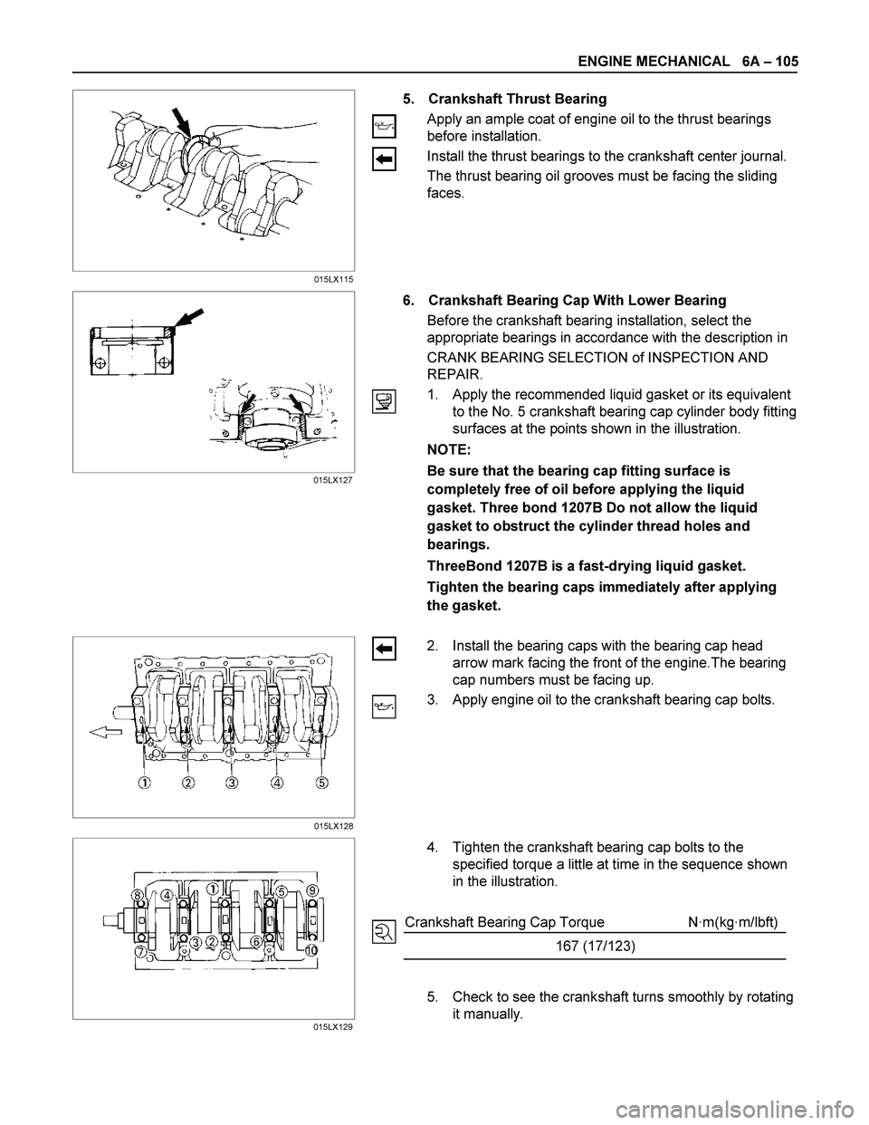
5. Crankshaft Thrust Bearing
Apply an ample coat of engine oil to the thrust bearings
before installation.
Install the thrust bearings to the crankshaft center journal.
The thrust bearing oil grooves must be facing the sliding
faces.
6. Crankshaft Bearing Cap With Lower Bearing
Before the crankshaft bearing installation, select the
appropriate bearings in accordance with the description in
CRANK BEARING SELECTION of INSPECTION AND
REPAIR.
1. Apply the recommended liquid gasket or its equivalent
to the No. 5 crankshaft bearing cap cylinder body fitting
surfaces at the points shown in the illustration.
NOTE:
Be sure that the bearing cap fitting surface is
completely free of oil before applying the liquid
gasket. Three bond 1207B Do not allow the liquid
gasket to obstruct the cylinder thread holes and
bearings.
ThreeBond 1207B is a fast-drying liquid gasket.
Tighten the bearing caps immediately after applying
the gasket.
2. Install the bearing caps with the bearing cap head
arrow mark facing the front of the engine.The bearing
cap numbers must be facing up.
3. Apply engine oil to the crankshaft bearing cap bolts.
4. Tighten the crankshaft bearing cap bolts to the
specified torque a little at time in the sequence shown
in the illustration.
Crankshaft Bearing Cap Torque N·m(kg·m/lbft)
167 (17/123)
5. Check to see the crankshaft turns smoothly by rotating
it manually.
015LX115
015LX127
015LX128
015LX129
Page 1246 of 4264

6A – 106 ENGINE MECHANICAL
7. Camshaft
1. Apply a coat of engine oil to the camshaft and the
camshaft bearings.
2. Install the camshaft to the cylinder body.
Take care not to damage the camshaft bearings.
8. Timing Gear Case
Tighten the timing gear case with timing gear case gasket
to the specified torque.
Timing Gear Case Bolt Torque N·m(kg·m/lbft)
19 (1.9/14)
9. Camshaft Thrust Plate
Install the thrust plate to the cylinder body and tighten the
thrust plate bolts to the specified torque.
Thrust Plate Bolt Torque N·m(kg·m/lbft)
19 (1.9/14)
RTW36ASH000901
10. Camshaft Timing Gear
1. Install the camshaft timing gear to the camshaft. The
timing gear mark must be facing outward.
2. Tighten the timing gear to the specified torque.
Timing Gear Bolt Torque N·m(kg·m/lbft)
110 (11.2/82)
014RY00019
020R300003
020RY00032