wiring ISUZU TF SERIES 2004 Workshop Manual
[x] Cancel search | Manufacturer: ISUZU, Model Year: 2004, Model line: TF SERIES, Model: ISUZU TF SERIES 2004Pages: 4264, PDF Size: 72.63 MB
Page 2617 of 4264
ENGINE DRIVEABILITY AND EMISSIONS 6E–41
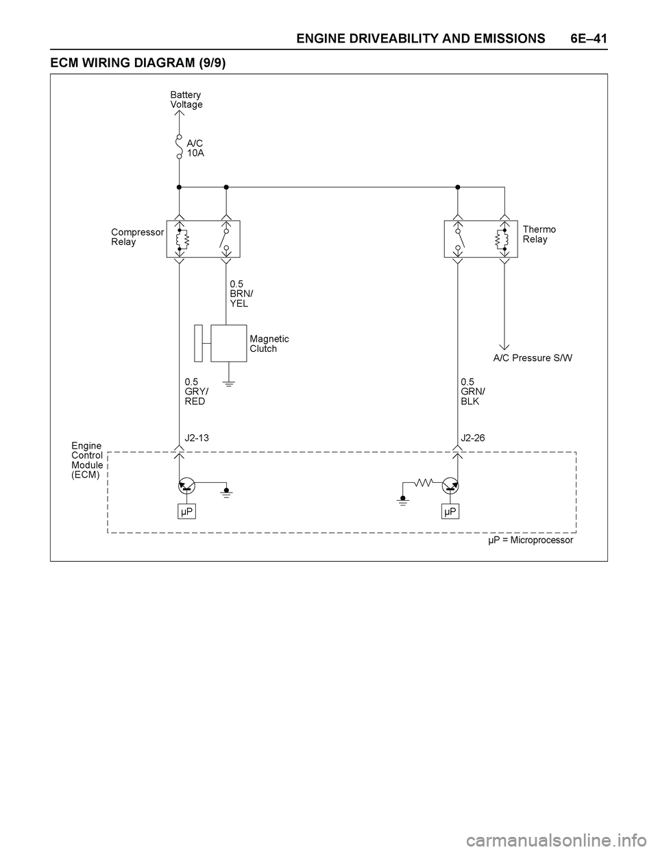
ECM WIRING DIAGRAM (9/9)
Page 2636 of 4264
6E–60 ENGINE DRIVEABILITY AND EMISSIONS
A/C CLUTCH DIAGNOSIS
A/C Clutch Circuit Operation
A 12-volt signal is supplied to the A/C request input of
the ECM when the A/C is selected through the A/C
control switch.
The A/C compressor clutch relay is controlled through
the ECM. This allows the ECM to modify the idle air
control position prior to the A/C clutch engagement for
better idle quality. If the engine operating conditions are
within their specified calibrated acceptable ranges, the
ECM will enable the A/C compressor relay. This is done
by providing a ground path for the A/C relay coil within
the ECM. When the A/C compressor relay is enabled,
battery voltage is supplied to the compressor relay is
enabled, battery voltage is supplied to the compressor
clutch coil.
The ECM will enable the A/C compressor clutch
whenever the engine is running and the A/C has been
requested. The ECM will not enable the A/C
compressor clutch if any of the following conditions are
met:
The engine speed is greater than 6000 RPM.
The ECT is greater than 122°C (251°F).
The throttle is more than 95% open.
A/C Clutch Circuit Purpose
The A/C compressor operation is controlled by the
engine control module (ECM) for the following reasons:
It improves idle quality during compressor clutch
engagement.
It improves wide open throttle (WOT) performance.
It provides A/C compressor protection from operation
with incorrect refrigerant pressures.
The A/C electrical system consists of the following
components:
The A/C control switch.
The A/C refrigerant pressure switches.
The A/C compressor clutch.
The A/C compressor clutch relay.
The ECM.
A/C Request Signal
This signal tells the ECM when the A/C mode is
selected at the A/C control switch. The ECM uses this
input to adjust the idle speed before turning on the A/C
clutch. The A/C compressor will be inoperative if this
signal is not available to the ECM.
Refer to A/C Clutch Circuit Diagnosis for A/C wiring
diagrams and diagnosis for the A/C electrical system.
Page 2638 of 4264
6E–62 ENGINE DRIVEABILITY AND EMISSIONS
Diagnostic Thought Process
As you follow a diagnostic plan, every box on the
Strategy Based Diagnostics chart requires you to use
the diagnostic thought process. This method of thinking
optimizes your diagnosis in the following ways:
Improves your understanding and definition of the
customer complaint
Saves time by avoiding testing and/or replacing good
parts
Allows you to look at the problem from different
perspectives
Guides you to determine what level of understanding
about system operation is needed:
–Owner’s manual level
–Service manual level
–In-depth (engineering) level
–Owner’s manual level
–Service manual level
–In-depth (engineering) level
1. Verify the Complaint
What you should do
To verify the customer complaint, you need to know the
correct (normal) operating behavior of the system and
verify that the customer complaint is a valid failure of the
system.
The following information will help you verify the
complaint:
WHAT the vehicle model/options are
WHAT aftermarket and dealer-installed accessories
exist
WHAT related system(s) operate properly
WHEN the problem occurs
WHERE the problem occurs
HOW the problem occurs
HOW LONG the condition has ex isted (and if the
system ever worked correctly)
HOW OFTEN the problem occurs
Whether the severity of the problem has increased,
decreased or stayed the same
What resources you should use
Whenever possible, you should use the following
resources to assist you in verifying the complaint:
Service manual Theory or Circuit Description
sections
Service manual “System Performance Check”
Owner manual operational description
Technician ex perience
Identical vehicle for comparisonCircuit testing tools
Vehicle road tests
Complaint check sheet
Contact with the customer
2. Perform Preliminary Checks
NOTE: An estimated 10 percent of successful vehicle
repairs are diagnosed with this step!
What you should do
You perform preliminary checks for several reasons:
To detect if the cause of the complaint is VISUALLY
OBVIOUS
To identify parts of the system that work correctly
To accumulate enough data to correctly and
accurately search for a ISUZU Service Bulletin on
ISUZU Web site.
The initial checks may vary depending on the
complex ity of the system and may include the following
actions:
Operate the suspect system
Make a visual inspection of harness routing and
accessible/visible power and ground circuits
Check for blown fuses
Make a visual inspection for separated connectors
Make a visual inspection of connectors (includes
checking terminals for damage and tightness)
Check for any DTCs stored by the on-board
computers
Sense unusual noises, smells, vibrations or
mov ements
Investigate the vehicle service history (call other
dealerships, if appropriate)
What resources you should use
Whenever appropriate, you should use the following
resources for assistance in performing preliminary
checks:
Tech II or other technical equipment for viewing DTCs
Service manual information:
–Component locations
–Harness routing
–Wiring schematics
–Procedures for viewing DTCs
Dealership service history file
Vehicle road test
Identical vehicle or system for comparison
Page 2640 of 4264
6E–64 ENGINE DRIVEABILITY AND EMISSIONS
–Are there areas subjected to vibration or
movement (engine, transmission or
suspension)?
–Are there areas ex posed to moisture, road salt
or other corrosives (battery acid, oil or other
fluids)?
–Are there common mounting areas with other
systems/components?
–Have previous repairs been performed to wiring,
connectors, components or mounting areas
(causing pinched wires between panels and
drivetrain or suspension components without
causing and immediate problem)?
–Does the vehicle have aftermarket or dealer-
installed equipment (radios, telephone, etc.)
Step 2: Isolate the problem
At this point, you should have a good idea of what could
cause the present condition, as well as could not cause
the condition. Actions to take include the following:
Divide (and separate, where possible) the system or
circuit into smaller sections
Confine the problem to a smaller area of the vehicle
(start with main harness connections while removing
panels and trim as necessary in order to eliminate
large vehicle sections from further investigation)
For two or more circuits that do not share a common
power or ground, concentrate on areas where
harnesses are routed together or connectors are
shared (refer to the following hints)
Hints
Though the symptoms may vary, basic electrical failures
are generally caused by:
Loose connections:
–Open/high resistance in terminals, splices,
connectors or grounds
Incorrect connector/harness routing (usually in new
vehicles or after a repair has been made):
–Open/high resistance in terminals, splices,
connectors of grounds
Corrosion and wire damage:
–Open/high resistance in terminals, splices,
connectors of grounds
Component failure:
–Opens/short and high resistance in relays,
modules, switches or loads
Aftermarket equipment affecting normal operation of
other systems
You may isolate circuits by:
Unplugging connectors or removing a fuse to
separate one part of the circuit from another part
Operating shared circuits and eliminating those that
function normally from the suspect circuit
If only one component fails to operate, begin testingat the component
If a number of components do no operate, begin tests
at the area of commonality (such as power sources,
ground circuits, switches or major connectors)
What resources you should use
Whenever appropriate, you should use the following
resources to assist in the diagnostic process:
Service manual
Technical equipment (for data analysis)
Ex perience
Technical Assistance
Circuit testing tools
5d. Intermittent Diagnosis
By definition, an intermittent problem is one that does
not occur continuously and will occur when certain
conditions are met. All these conditions, however, may
not be obvious or currently known. Generally,
intermittents are caused by:
Faulty electrical connections and wiring
Malfunctioning components (such as sticking relays,
solenoids, etc.)
EMI/RFI (Electromagnetic/radio frequency
interference)
Aftermarket equipment
Intermittent diagnosis requires careful analysis of
suspected systems to help prevent replacing good
parts. This may involve using creativity and ingenuity to
interpret customer complaints and simulating all
ex ternal and internal system conditions to duplicate the
problem.
What you should do
Step 1: A cquire information
A thorough and comprehensive customer check sheet
is critical to intermittent problem diagnosis. You should
require this, since it will dictate the diagnostic starting
point. The vehicle service history file is another
source for accumulating information about the
complaint.
Step 2: A nalyze the intermittent problem
Analyze the customer check sheet and service history
file to determine conditions relevant to the suspect
system(s).
Using service manual information, you must identify,
trace and locate all electrical circuits related to the
malfunctioning system(s). If there is more than one
system failure, you should identify, trace and locate
areas of commonality shared by the suspect circuits.
Page 2674 of 4264
6E–98 ENGINE DRIVEABILITY AND EMISSIONS
FUEL METERING SYSTEM CHECK
Some failures of the fuel metering system will result in
an “Engine Cranks But Will Not Run” symptom. If this
condition ex ists, refer to the Cranks But Will Not Run
chart. This chart will determine if the problem is caused
by the ignition system, the ECM, or the fuel pump
electrical circuit.
Refer to Fuel System Electrical Test for the fuel system
wiring schematic.
If there is a fuel delivery problem, refer to Fuel System
Diagnosis, which diagnoses the fuel injectors, the fuel
pressure regulator, and the fuel pump.
Followings are applicable to the vehicles with
closed Loop System:
If a malfunction occurs in the fuel metering system, it
usually results in either a rich HO2S signal or a lean
HO2S signal. This condition is indicated by the HO2S
voltage, which causes the ECM to change the fuel
calculation (fuel injector pulse width) based on the
HO2S reading. Changes made to the fuel calculation
will be indicated by a change in the long term fuel trim
values which can be monitored with a Scan Tool. Ideal
long term fuel trim values are around 0%; for a lean
HO2S signal, the ECM will add fuel, resulting in a fuel
trim value above 0%. Some variations in fuel trim values
are normal because all engines are not ex actly the
same. If the evaporative emission canister purge is 02
status may be rich condition. 02 status indicates the
lean condition, refer to DTC P1171 for items which can
cause a lean HO2S signal.
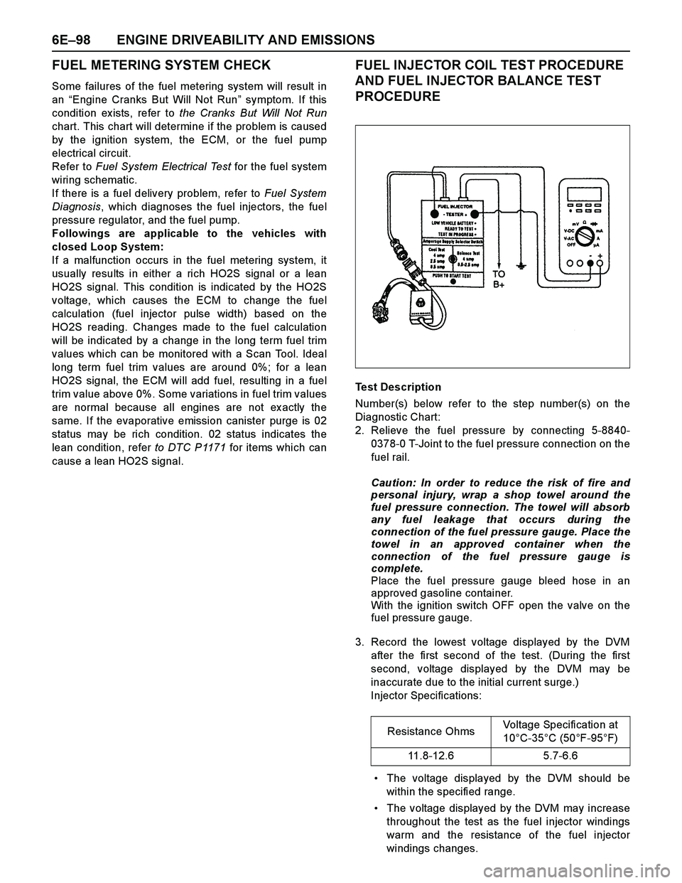
FUEL INJECTOR COIL TEST PROCEDURE
AND FUEL INJECTOR BALANCE TEST
PROCEDURE
Test Description
Number(s) below refer to the step number(s) on the
Diagnostic Chart:
2. Relieve the fuel pressure by connecting 5-8840-
0378-0 T-Joint to the fuel pressure connection on the
fuel rail.
Caution: In order to reduce the risk of fire and
personal injury, wrap a shop towel around the
fuel pressure connection. The towel will absorb
any fuel leakage that occurs during the
connection of the fuel pressure gauge. Place the
towel in an approved container when the
connection of the fuel pressure gauge is
complete.
Place the fuel pressure gauge bleed hose in an
approved gasoline container.
With the ignition switch OFF open the valve on the
fuel pressure gauge.
3. Record the lowest voltage displayed by the DVM
after the first second of the test. (During the first
second, voltage displayed by the DVM may be
inaccurate due to the initial current surge.)
Injector Specifications:
The voltage displayed by the DVM should be
within the specified range.
The voltage displayed by the DVM may increase
throughout the test as the fuel injector windings
warm and the resistance of the fuel injector
windings changes.Resistance OhmsVoltage Specification at
10°C-35°C (50°F-95°F)
11.8-12.6 5.7-6.6
Page 2696 of 4264
6E–120 ENGINE DRIVEABILITY AND EMISSIONS
connectors for backed-out terminals, improper
mating, broken locks, improperly formed or damaged
terminals, and poor terminal-to-wire connection.
If these codes are also set, it could indicate a
problem with the 5 Volt reference circuit.
Damaged harness - Inspect the wiring harness fordamage, short to ground, short to battery positive,
and open circuit. If the harness appears to be OK,
observe the MAP display on the Tech 2 while moving
connectors and wiring harnesses related to the
sensor. A change in the display will indicate the
location of the fault.
Diagnostic Trouble Code (DTC) P0107
Manifold Absolute Pressure Circuit Low Input
Step A ction Value(s) Yes No
1 Was the “On-Board Diagnostic (OBD) System Check”
performed?
—Go to Step 2Go to On Board
Diagnostic
(OBD) System
Check
2 1. Connect the Tech 2.
2. Review and record the failure information.
3. Select “F0: Read DTC Infor By Priority” in “F0:
Diagnostic Trouble Code”.
Is the DTC P0107 stored as “Present Failure”?—Go to Step 3Refer to
Diagnostic Aids
and Go to Step
3
3 1. Using the Tech2, ignition “On” and engine “Off”.
2. Select “Clear DTC Information” with the Tech2 and
clear the DTC information.
3. Operate the vehicle and monitor the “F5: Failed
This Ignition” in “F2: DTC Information”.
Was the DTC P0107 stored in this ignition cycle?—Go to Step 4Refer to
Diagnostic Aids
and Go to Step
4
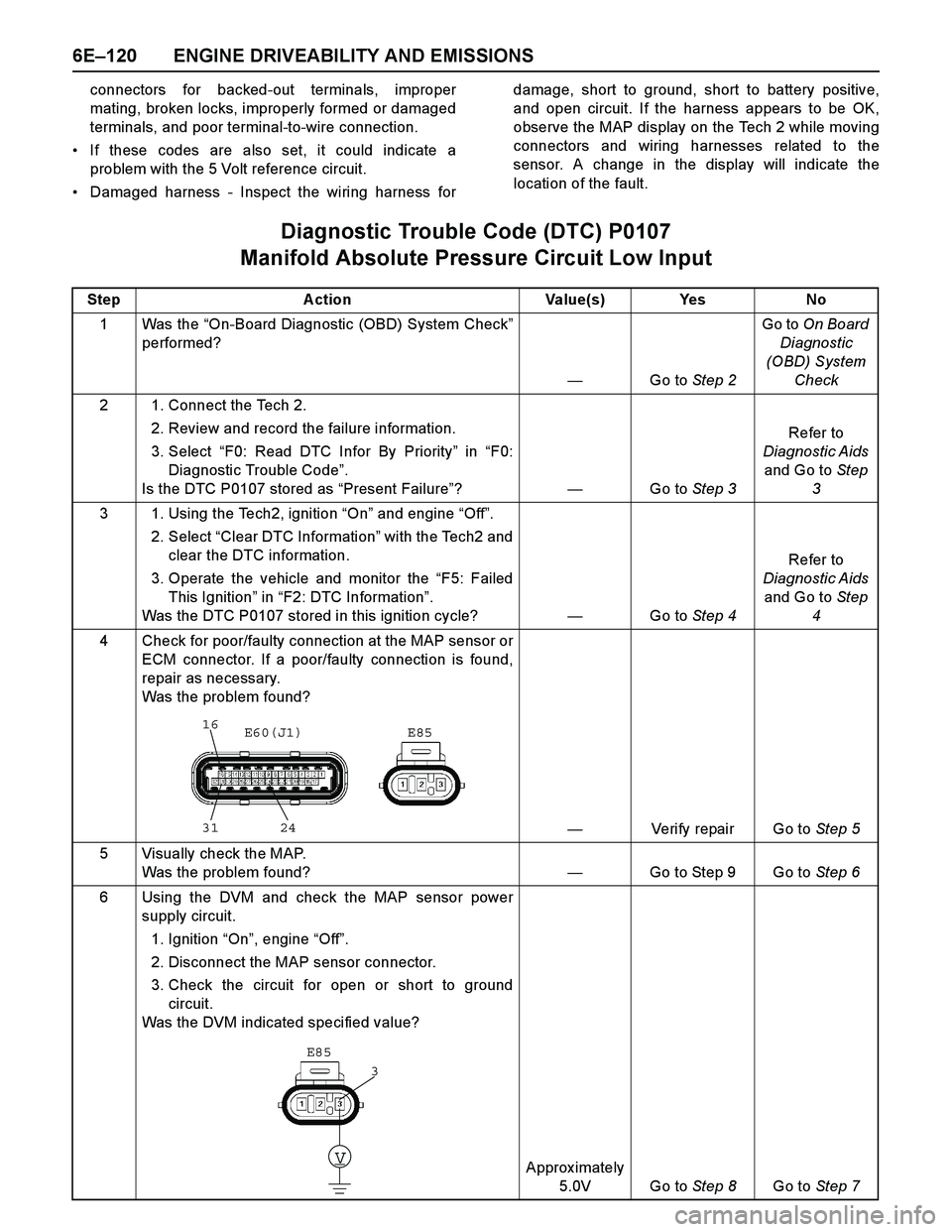
4 Check for poor/faulty connection at the MAP sensor or
ECM connector. If a poor/faulty connection is found,
repair as necessary.
Was the problem found?
—Verify repair Go to Step 5
5 Visually check the MAP.
Was the problem found? —Go to Step 9 Go to Step 6
6 Using the DVM and check the MAP sensor power
supply circuit.
1. Ignition “On”, engine “Off”.
2. Disconnect the MAP sensor connector.
3. Check the circuit for open or short to ground
circuit.
Was the DVM indicated specified value?
Approx imately
5.0V Go to Step 8Go to Step 7
16
31 24E85 E60(J1)
V
E85
3
Page 2700 of 4264
6E–124 ENGINE DRIVEABILITY AND EMISSIONS
Diagnostic Aids
Check for the following conditions:
Poor connection at ECM - Inspect harness
connectors for backed-out terminals, improper
mating, broken locks, improperly formed or damaged
terminals, and poor terminal-to-wire connection.
If these codes are also set, it could indicate aproblem with the 5 Volt reference circuit.
Damaged harness - Inspect the wiring harness for
damage; an open circuit, a short to ground, or a short
to voltage. If the harness appears to be OK, observe
the MAP display on the Tech 2 while moving
connectors and wiring harnesses related to the
sensor. A change in the display will indicate the
location of the fault.
Diagnostic Trouble Code (DTC) P0108
Manifold Absolute Pressure Circuit High Input
Step Action Value(s) Yes No
1Was the “On-Board Diagnostic (OBD) System Check”
performed?
—Go to Step 2Go to On Board
Diagnostic
(OBD) System
Check
2 1. Connect the Tech 2.
2. Review and record the failure information.
3. Select “F0: Read DTC Infor By Priority” in “F0:
Diagnostic Trouble Code”.
Is the DTC P0108 stored as “Present Failure”?—Go to Step 3Refer to
Diagnostic Aids
and Go to Step
3
3 1. Using the Tech2, ignition “On” and engine “Off”.
2. Select “Clear DTC Information” with the Tech2 and
clear the DTC information.
3. Operate the vehicle and monitor the “F5: Failed
This Ignition” in “F2: DTC Information”.
Was the DTC P0108 stored in this ignition cycle?—Go to Step 4Refer to
Diagnostic Aids
and Go to Step
4
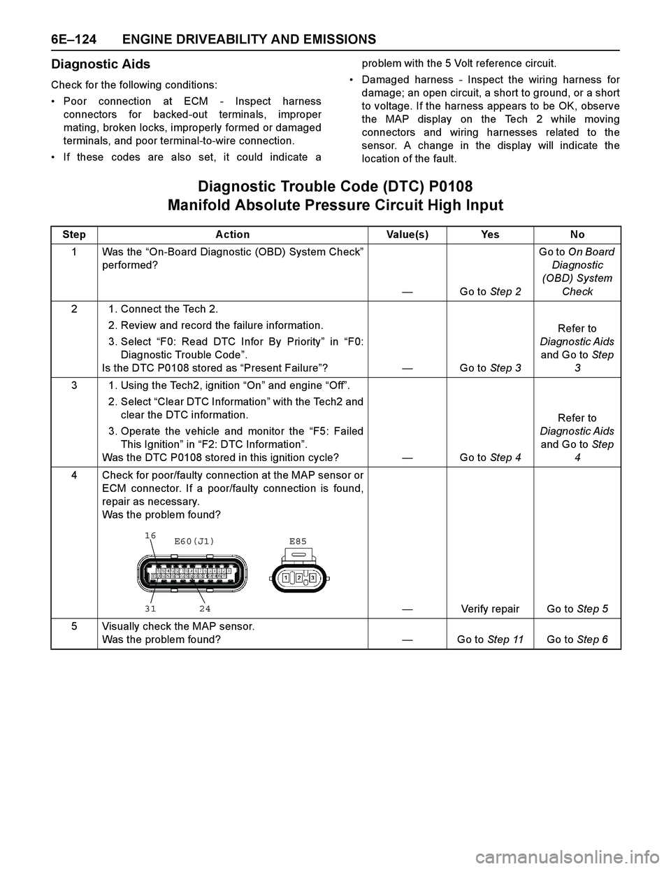
4 Check for poor/faulty connection at the MAP sensor or
ECM connector. If a poor/faulty connection is found,
repair as necessary.
Was the problem found?
—Verify repair Go to Step 5
5 Visually check the MAP sensor.
Was the problem found?—Go to Step 11Go to Step 6
16
31 24E85 E60(J1)
Page 2703 of 4264
ENGINE DRIVEABILITY AND EMISSIONS 6E–127
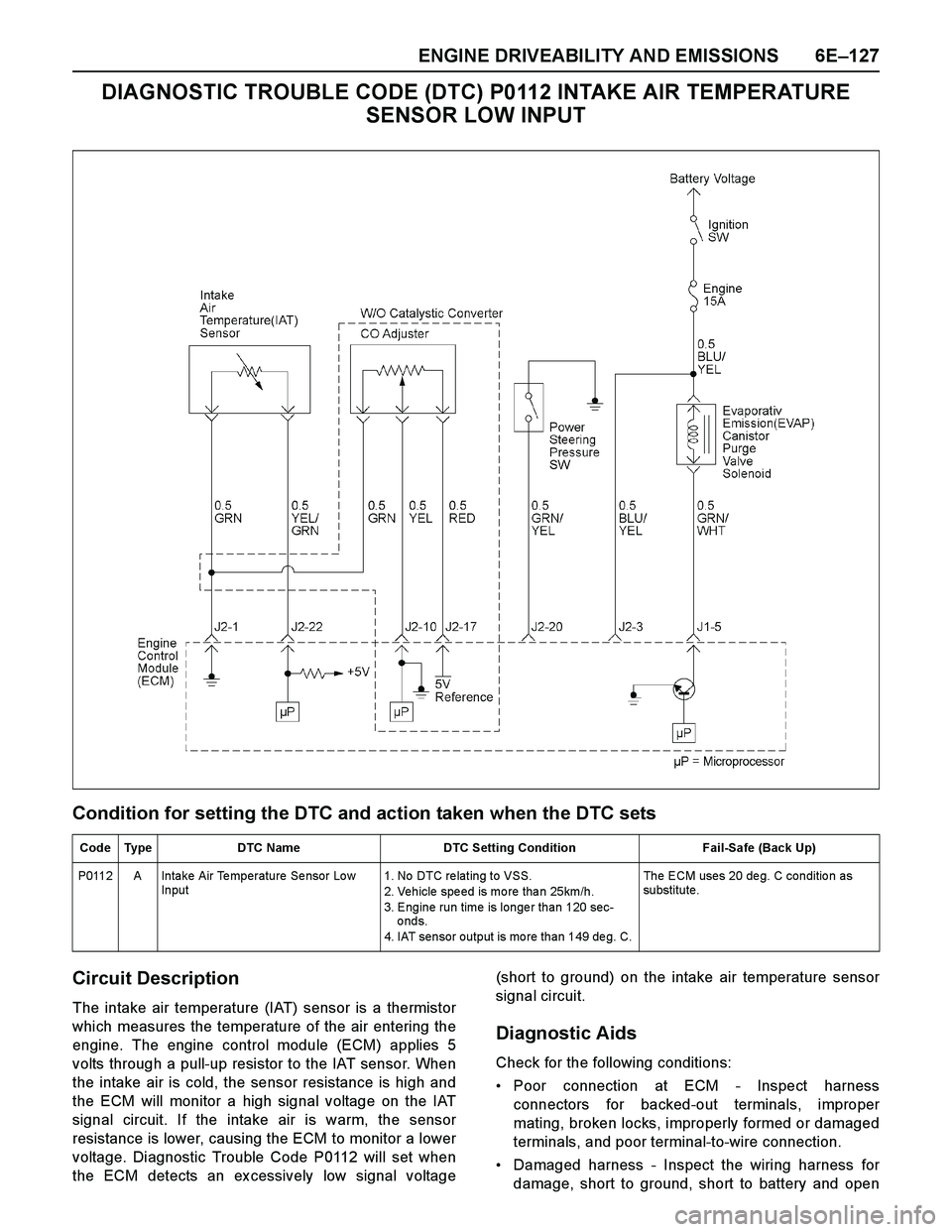
DIAGNOSTIC TROUBLE CODE (DTC) P0112 INTAKE AIR TEMPERATURE
SENSOR LOW INPUT
Condition for setting the DTC and action taken when the DTC sets
Circuit Description
The intake air temperature (IAT) sensor is a thermistor
which measures the temperature of the air entering the
engine. The engine control module (ECM) applies 5
volts through a pull-up resistor to the IAT sensor. When
the intake air is cold, the sensor resistance is high and
the ECM will monitor a high signal voltage on the IAT
signal circuit. If the intake air is warm, the sensor
resistance is lower, causing the ECM to monitor a lower
voltage. Diagnostic Trouble Code P0112 will set when
the ECM detects an ex cessively low signal voltage(short to ground) on the intake air temperature sensor
signal circuit.
Diagnostic Aids
Check for the following conditions:
Poor connection at ECM - Inspect harness
connectors for backed-out terminals, improper
mating, broken locks, improperly formed or damaged
terminals, and poor terminal-to-wire connection.
Damaged harness - Inspect the wiring harness for
damage, short to ground, short to battery and open
Code Type DTC Name DTC Setting Condition Fail-Safe (Back Up)
P0112 A Intake Air Temperature Sensor Low
Input1. No DTC re lating to VSS.
2. Vehicle spe ed is mo re tha n 25km/h.
3. Engine run time is longer than 120 sec-
onds.
4. IAT sensor output is more than 149 deg. C. The ECM uses 20 de g. C conditio n as
substitute.
Page 2704 of 4264
6E–128 ENGINE DRIVEABILITY AND EMISSIONS
circuit. If the harness appears to be OK, observe the
IAT display on the Tech 2 while moving connectors
and wiring harnesses related to the IAT sensor. Achange in the IAT display will indicate the location of
the fault.
Diagnostic Trouble Code (DTC) P0112
Intake Air Temperature Sensor Low Input
Step A ction Value(s) Yes No
1 Was the “On-Board Diagnostic (OBD) System Check”
performed?
—Go to Step 2Go to On Board
Diagnostic
(OBD) System
Check
2 1. Connect the Tech 2.
2. Review and record the failure information.
3. Select “F0: Read DTC Infor By Priority” in “F0:
Diagnostic Trouble Code”.
Is the DTC P0112 stored as “Present Failure”?—Go to Step 3Refer to
Diagnostic Aids
and Go to Step
3
3 1. Using the Tech2, ignition “On” and engine “Off”.
2. Select “Clear DTC Information” with the Tech2 and
clear the DTC information.
3. Operate the vehicle and monitor the “F5: Failed
This Ignition” in “F2: DTC Information”.
Was the DTC P0112 stored in this ignition cycle?—Go to Step 4Refer to
Diagnostic Aids
and Go to Step
4
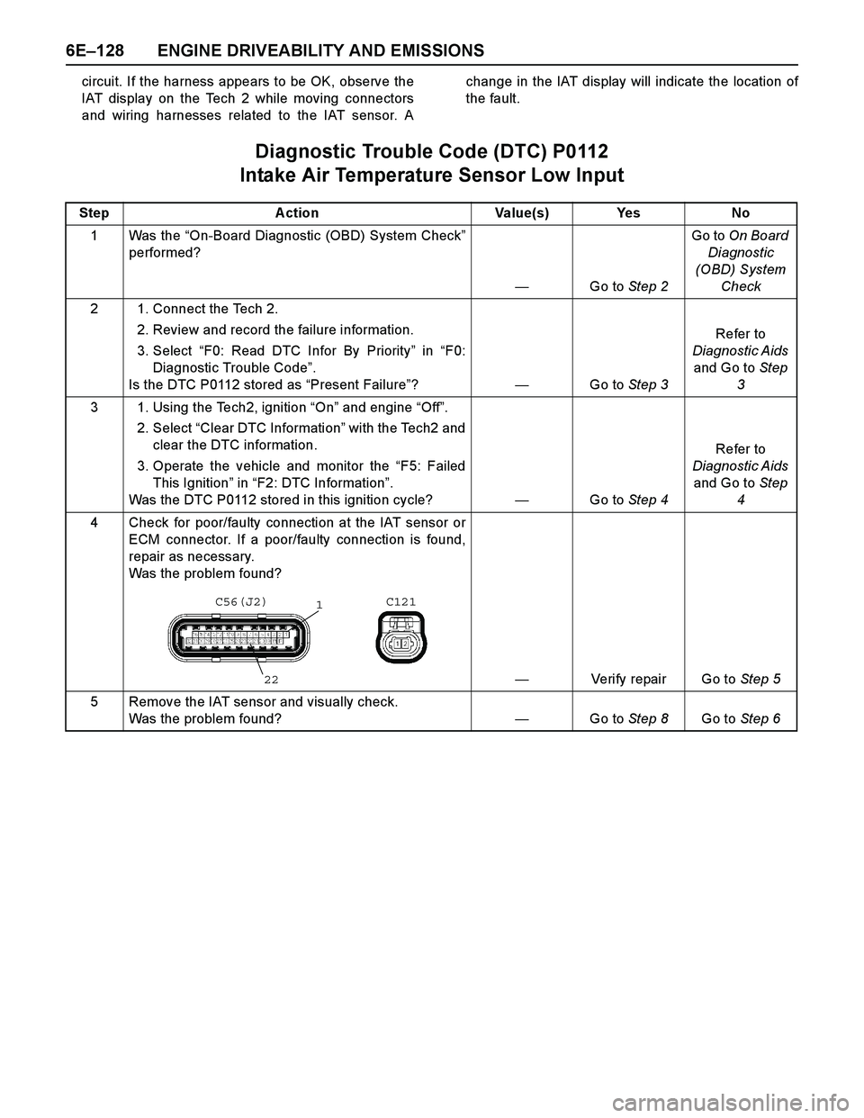
4 Check for poor/faulty connection at the IAT sensor or
ECM connector. If a poor/faulty connection is found,
repair as necessary.
Was the problem found?
—Verify repair Go to Step 5
5 Remove the IAT sensor and visually check.
Was the problem found? —Go to Step 8Go to Step 6
C56(J2) C121
1
22
Page 2708 of 4264
6E–132 ENGINE DRIVEABILITY AND EMISSIONS
terminals, and poor terminal-to-wire connection.
Damaged harness - Inspect the wiring harness for
damage, short to ground, short to battery positive,
and open circuit. If the harness appears to be OK,observe the IAT display on the Tech 2 while moving
connectors and wiring harnesses related to the IAT
sensor. A change in the IAT display will indicate the
location of the fault.
Diagnostic Trouble Code (DTC) P0113
Intake Air Temperature Sensor High Input
Step A ction Value(s) Yes No
1 Was the “On-Board Diagnostic (OBD) System Check”
performed?
—Go to Step 2Go to On Board
Diagnostic
(OBD) System
Check
2 1. Connect the Tech 2.
2. Review and record the failure information.
3. Select “F0: Read DTC Infor By Priority” in “F0:
Diagnostic Trouble Code”.
Is the DTC P0113 stored as “Present Failure”?—Go to Step 3Refer to
Diagnostic Aids
and Go to Step
3
3 1. Using the Tech2, ignition “On” and engine “Off”.
2. Select “Clear DTC Information” with the Tech2 and
clear the DTC information.
3. Operate the vehicle and monitor the “F5: Failed
This Ignition” in “F2: DTC Information”.
Was the DTC P0113 stored in this ignition cycle?—Go to Step 4Refer to
Diagnostic Aids
and Go to Step
4
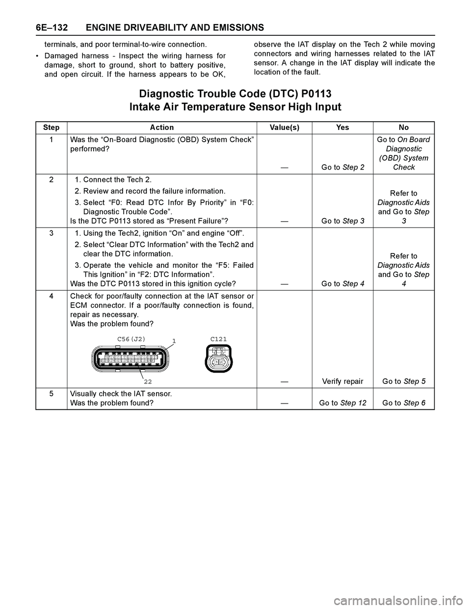
4 Check for poor/faulty connection at the IAT sensor or
ECM connector. If a poor/faulty connection is found,
repair as necessary.
Was the problem found?
—Verify repair Go to Step 5
5 Visually check the IAT sensor.
Was the problem found? —Go to Step 12Go to Step 6
C56(J2) C121
1
22