ISUZU TF SERIES 2004 Workshop Manual
Manufacturer: ISUZU, Model Year: 2004, Model line: TF SERIES, Model: ISUZU TF SERIES 2004Pages: 4264, PDF Size: 72.63 MB
Page 2401 of 4264

INDUCTION (6VE1 3.5L) 6J-1
ENGINE
INDUCTION (6VE1 3.5L)
CONTENTS
Service Precaution................................................. 6J-1
Air Cleaner Element............................................... 6J-2
Removal............................................................... 6J-2
Inspection............................................................. 6J-2
Installation............................................................. 6J-2
Service Precaution
WARNING: THIS VEHICLE HAS A SUPPLEMENTAL
RESTRAINT SYSTEM (SRS). REFER TO THE SRS
COMPONENT AND WIRING LOCATION VIEW IN
ORDER TO DETERMINE WHETHER YOU ARE
PERFORMING SERVICE ON OR NEAR THE SRS
COMPONENTS OR THE SRS WIRING. WHEN YOU
ARE PERFORMING SERVICE ON OR NEAR THE
SRS COMPONENTS OR THE SRS WIRING, REFE
R
TO THE SRS SERVICE INFORMATION. FAILURE TO
FOLLOW WARNINGS COULD RESULT IN
POSSIBLE AIR BAG DEPLOYMENT, PERSONAL
INJURY, OR OTHERWISE UNNEEDED SRS SYSTEM
REPAIRS.
CAUTION: Always use the correct fastener in the
proper location. When you replace a fastener, use
ONLY the exact part number for that application.
ISUZU will call out those fasteners that require a
replacement after removal. ISUZU will also call out
the fasteners that require thread lockers or thread
sealant. UNLESS OTHERWISE SPECIFIED, do not
use supplemental coatings (Paints, greases, o
r
other corrosion inhibitors) on threaded fasteners o
r
fastener joint interfaces. Generally, such coatings
adversely affect the fastener torque and the joint
clamping force, and may damage the fastener.
When you install fasteners, use the correct
tightening sequence and specifications. Following
these instructions can help you avoid damage to
parts and systems.
Page 2402 of 4264
6J-2 INDUCTION (6VE1 3.5L)
Air Cleaner
Removal
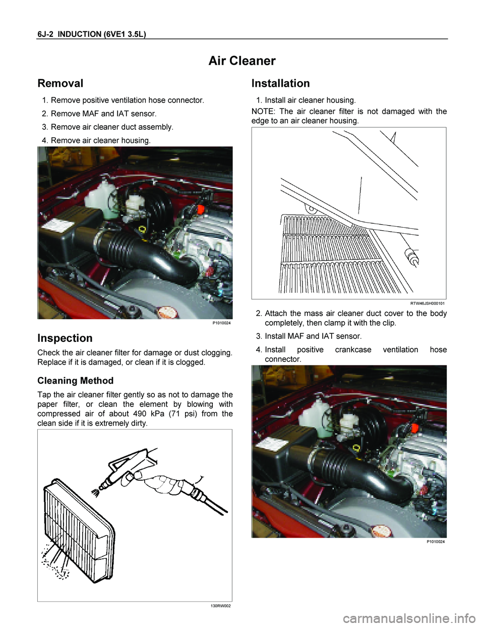
1. Remove positive ventilation hose connector.
2. Remove MAF and IAT sensor.
3. Remove air cleaner duct assembly.
4. Remove air cleaner housing.
P1010024
Inspection
Check the air cleaner filter for damage or dust clogging.
Replace if it is damaged, or clean if it is clogged.
Cleaning Method
Tap the air cleaner filter gently so as not to damage the
paper filter, or clean the element by blowing with
compressed air of about 490 kPa (71 psi) from the
clean side if it is extremely dirty.
130RW002
Installation
1. Install air cleaner housing.
NOTE: The air cleaner filter is not damaged with the
edge to an air cleaner housing.
RTW46JSH000101
2. Attach the mass air cleaner duct cover to the body
completely, then clamp it with the clip.
3. Install MAF and IAT sensor.
4. Install positive crankcase ventilation hose connector.
P1010024
Page 2403 of 4264

Page 2404 of 4264

No. TF6VE-WE-0431
Page 2405 of 4264
WORKSHOP MANUAL
TF SERIES
ENGINE
C24SE
SECTION 6
Page 2406 of 4264

Page 2407 of 4264
ENGINE DIAGNOSIS (C24SE) 6-1
SECTION 6
ENGINE DIAGNOSIS
CONTENTS
PAGE
Engine Diagnosis............................................................................................................... 6- 2
Hard Starting ................................................................................................................. 6- 2
Engine Compression Test Procedure ......................................................................... 6- 3
Rough Engine Idling or Engine Stalling ...................................................................... 6- 4
Rough Engine Running ................................................................................................ 6- 5
Hesitation....................................................................................................................... 6- 6
Engine Lacks Power ..................................................................................................... 6- 7
Engine Noisy ................................................................................................................. 6- 8
Abnormal Noise Due to Hydraulic Lash Adjustor ...................................................... 6- 9
Troubleshooting Procedure ......................................................................................... 6- 9
Abnormal Combustion.................................................................................................. 6-11
Engine Oil Consumption Excessive ............................................................................ 6-12
Fuel Consumption Excessive ...................................................................................... 6-13
Oil Problems .................................................................................................................. 6-13
Engine Oil Pressure Check .......................................................................................... 6-13
Malfunction Indicator Lamp ......................................................................................... 6-14
Page 2408 of 4264
6-2 ENGINE DIAGNOSIS (C24SE)
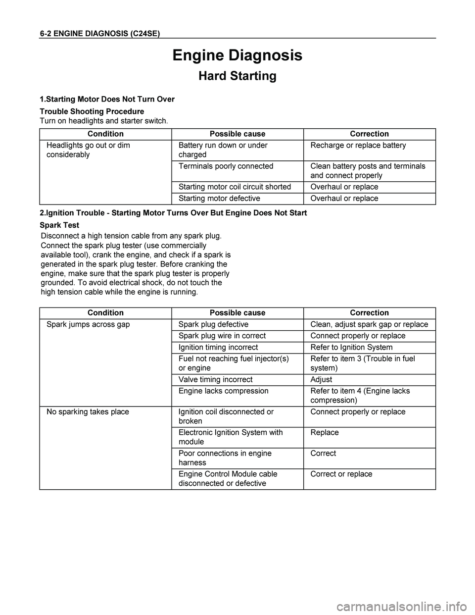
Engine Diagnosis
Hard Starting
1.Starting Motor Does Not Turn Over
Trouble Shooting Procedure
Turn on headlights and starter switch.
Condition Possible cause Correction
Headlights go out or dim
considerably Battery run down or under
charged Recharge or replace battery
Terminals poorly connected Clean battery posts and terminals
and connect properly
Starting motor coil circuit shorted Overhaul or replace
Starting motor defective Overhaul or replace
2.Ignition Trouble - Starting Motor Turns Over But Engine Does Not Start
Spark Test
Disconnect a high tension cable from any spark plug.
Connect the spark plug tester (use commercially
available tool), crank the engine, and check if a spark is
generated in the spark plug tester. Before cranking the
engine, make sure that the spark plug tester is properly
grounded. To avoid electrical shock, do not touch the
high tension cable while the engine is running.
Condition Possible cause Correction
Spark jumps across gap Spark plug defective Clean, adjust spark gap or replace
Spark plug wire in correct Connect properly or replace
Ignition timing incorrect Refer to Ignition System
Fuel not reaching fuel injector(s)
or engine Refer to item 3 (Trouble in fuel
system)
Valve timing incorrect Adjust
Engine lacks compression Refer to item 4 (Engine lacks
compression)
No sparking takes place Ignition coil disconnected or
broken Connect properly or replace
Electronic Ignition System with
module Replace
Poor connections in engine
harness Correct
Engine Control Module cable
disconnected or defective Correct or replace
Page 2409 of 4264
ENGINE DIAGNOSIS (C24SE) 6-3
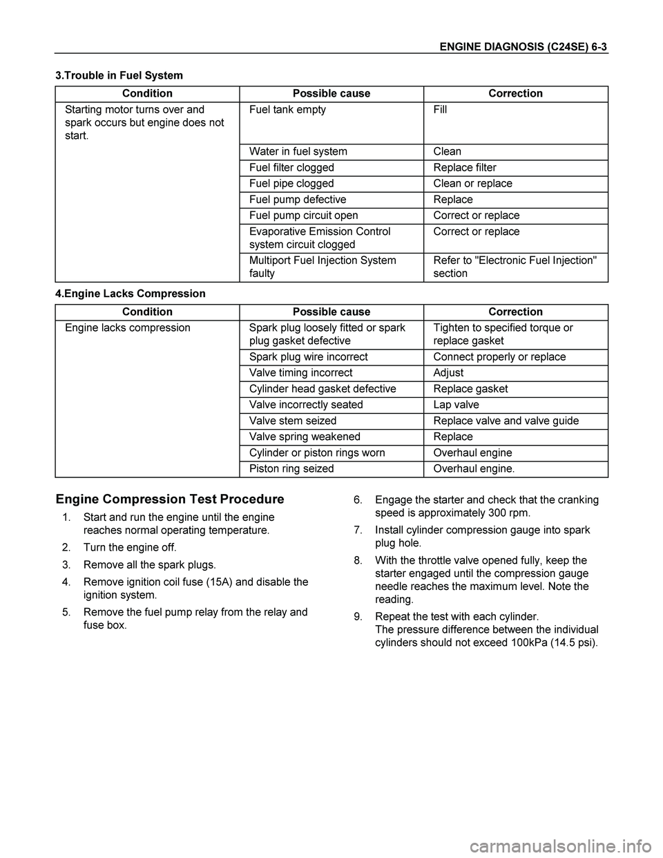
3.Trouble in Fuel System
Condition Possible cause Correction
Starting motor turns over and
spark occurs but engine does not
start. Fuel tank empty Fill
Water in fuel system Clean
Fuel filter clogged Replace filter
Fuel pipe clogged Clean or replace
Fuel pump defective Replace
Fuel pump circuit open Correct or replace
Evaporative Emission Control
system circuit clogged Correct or replace
Multiport Fuel Injection System
faulty Refer to "Electronic Fuel Injection"
section
4.Engine Lacks Compression
Condition Possible cause Correction
Engine lacks compression Spark plug loosely fitted or spark
plug gasket defective Tighten to specified torque or
replace gasket
Spark plug wire incorrect Connect properly or replace
Valve timing incorrect Adjust
Cylinder head gasket defective Replace gasket
Valve incorrectly seated Lap valve
Valve stem seized Replace valve and valve guide
Valve spring weakened Replace
Cylinder or piston rings worn Overhaul engine
Piston ring seized Overhaul engine.
Engine Compression Test Procedure
1. Start and run the engine until the engine
reaches normal operating temperature.
2. Turn the engine off.
3. Remove all the spark plugs.
4. Remove ignition coil fuse (15A) and disable the
ignition system.
5. Remove the fuel pump relay from the relay and
fuse box. 6. Engage the starter and check that the cranking
speed is approximately 300 rpm.
7. Install cylinder compression gauge into spark
plug hole.
8. With the throttle valve opened fully, keep the
starter engaged until the compression gauge
needle reaches the maximum level. Note the
reading.
9. Repeat the test with each cylinder.
The pressure difference between the individual
cylinders should not exceed 100kPa (14.5 psi).
Page 2410 of 4264
6-4 ENGINE DIAGNOSIS (C24SE)
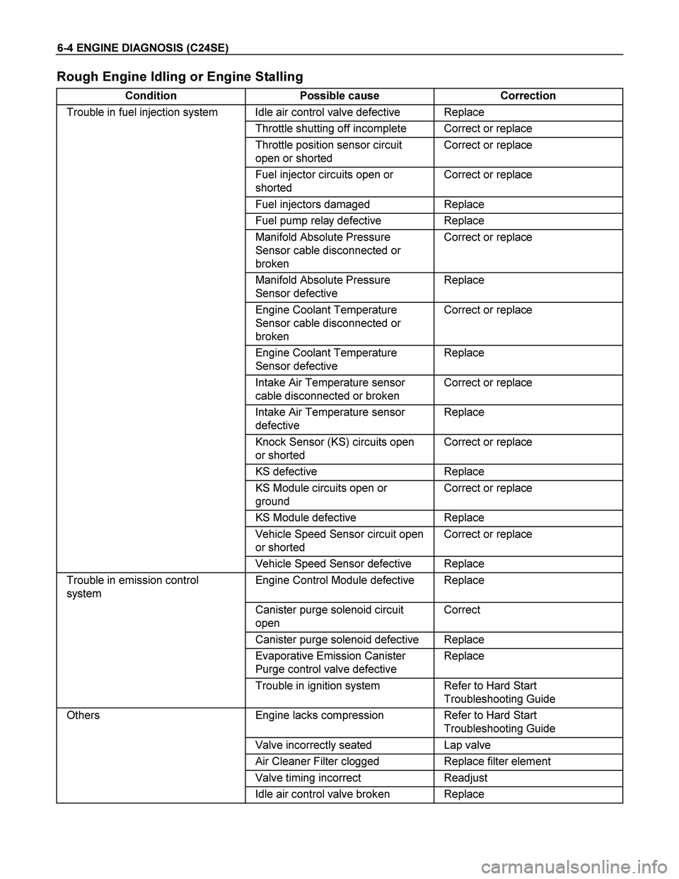
Rough Engine Idling or Engine Stalling
Condition Possible cause Correction
Trouble in fuel injection system Idle air control valve defective Replace
Throttle shutting off incomplete Correct or replace
Throttle position sensor circuit
open or shorted Correct or replace
Fuel injector circuits open or
shorted Correct or replace
Fuel injectors damaged Replace
Fuel pump relay defective Replace
Manifold Absolute Pressure
Sensor cable disconnected or
broken Correct or replace
Manifold Absolute Pressure
Sensor defective Replace
Engine Coolant Temperature
Sensor cable disconnected or
broken Correct or replace
Engine Coolant Temperature
Sensor defective Replace
Intake Air Temperature sensor
cable disconnected or broken Correct or replace
Intake Air Temperature sensor
defective Replace
Knock Sensor (KS) circuits open
or shorted Correct or replace
KS defective Replace
KS Module circuits open or
ground Correct or replace
KS Module defective Replace
Vehicle Speed Sensor circuit open
or shorted Correct or replace
Vehicle Speed Sensor defective Replace
Trouble in emission control
system Engine Control Module defective Replace
Canister purge solenoid circuit
open Correct
Canister purge solenoid defective Replace
Evaporative Emission Canister
Purge control valve defective Replace
Trouble in ignition system Refer to Hard Start
Troubleshooting Guide
Others Engine lacks compression Refer to Hard Start
Troubleshooting Guide
Valve incorrectly seated Lap valve
Air Cleaner Filter clogged Replace filter element
Valve timing incorrect Readjust
Idle air control valve broken Replace