wiring ISUZU TF SERIES 2004 Workshop Manual
[x] Cancel search | Manufacturer: ISUZU, Model Year: 2004, Model line: TF SERIES, Model: ISUZU TF SERIES 2004Pages: 4264, PDF Size: 72.63 MB
Page 3590 of 4264
7D-2 TRANSFER CASE
Service Precaution
WARNING: THIS VEHICLE HAS A SUPPLEMENTAL
RESTRAINT SYSTEM (SRS). REFER TO THE SRS
COMPONENT AND WIRING LOCATION VIEW IN
ORDER TO DETERMINE WHETHER YOU ARE
PERFORMING SERVICE ON OR NEAR THE SRS
COMPONENTS OR THE SRS WIRING. WHEN YOU
ARE PERFORMING SERVICE ON OR NEAR THE
SRS COMPONENTS OR THE SRS WIRING, REFER
TO THE SRS SERVICE INFORMATION. FAILURE TO
FOLLOW WARNINGS COULD RESULT IN
POSSIBLE AIR BAG DEPLOYMENT, PERSONAL
INJURY, OR OTHERWISE UNNEEDED SRS SYSTEM
REPAIRS.
CAUTION: Always use the correct fastener in the
proper location. When you replace a fastener, use
ONLY the exact part number for that application.
ISUZU will call out those fasteners that require a
replacement after removal. ISUZU will also call out
the fasteners that require thread lockers or thread
sealant. UNLESS OTHERWISE SPECIFIED, do not
use supplemental coatings (Paints, greases, or
other corrosion inhibitors) on threaded fasteners or
fastener joint interfaces. Generally, such coatings
adversely affect the fastener torque and the joint
clamping force, and may damage the fastener.
When you install fasteners, use the correct
tightening sequence and specifications. Following
these instructions can help you avoid damage to
parts and systems.
Page 3628 of 4264
7D1-2 TRANSFER CONTROL SYSTEM
Service Precaution
WARNING:
THIS VEHICLE HAS A SUPPLEMENTAL RESTRAINT
SYSTEM (SRS). REFER TO THE SRS COMPONENT AND
WIRING LOCATION VIEW IN ORDER TO DETERMINE
WHETHER YOU ARE PERFORMING SERVICE ON OR
NEAR THE SRS COMPONENTS OR THE SRS WIRING.
WHEN YOU ARE PERFORMING SERVICE ON OR NEAR
THE SRS COMPONENTS OR THE SRS WIRING, REFER TO
THE SRS SERVICE INFORMATION. FAILURE TO FOLLOW
WARNINGS COULD RESULT IN POSSIBLE AIR BAG
DEPLOYMENT, PERSONAL INJURY, OR OTHERWISE
UNNEEDED SRS SYSTEM REPAIRS.
CAUTION:
Always use the correct fastener in the proper location.
When you replace a fastener, use ONLY the exact part
number for that application. ISUZU will call out those
fasteners that require a replacement after removal. ISUZU
will also call out the fasteners that require thread lockers
or thread sealant. UNLESS OTHERWISE SPECIFIED, do
not use supplemental coatings (Paints, greases, or other
corrosion inhibitors) on threaded fasteners or fastener
joint interfaces. Generally, such coatings adversely affect
the fastener torque and the joint clamping force, and may
damage the fastener. When you install fasteners, use the
correct tightening sequence and specifications. Following
these instructions can help you avoid damage to parts
and systems.
Page 3636 of 4264
7D1-10 TRANSFER CONTROL SYSTEM
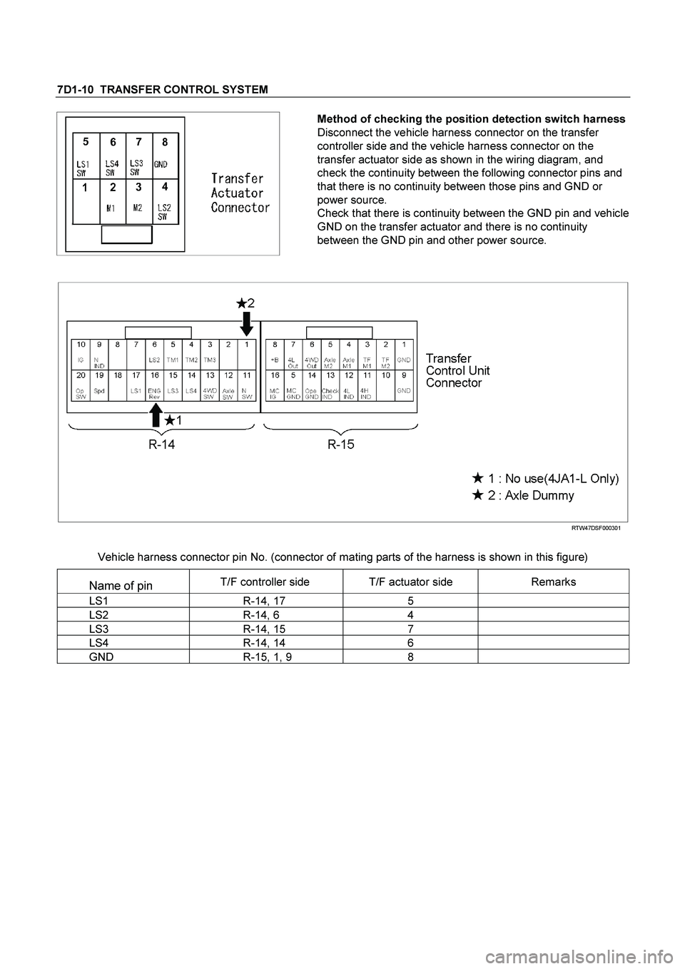
Method of checking the position detection switch harness
Disconnect the vehicle harness connector on the transfer
controller side and the vehicle harness connector on the
transfer actuator side as shown in the wiring diagram, and
check the continuity between the following connector pins and
that there is no continuity between those pins and GND or
power source.
Check that there is continuity between the GND pin and vehicle
GND on the transfer actuator and there is no continuity
between the GND pin and other power source.
RTW47DSF000301
Vehicle harness connector pin No. (connector of mating parts of the harness is shown in this figure)
Name of pin T/F controller side T/F actuator side Remarks
LS1 R-14, 17 5
LS2 R-14, 6 4
LS3 R-14, 15 7
LS4 R-14, 14 6
GND R-15, 1, 9 8
Page 3674 of 4264
7D1-48 TRANSFER CONTROL SYSTEM
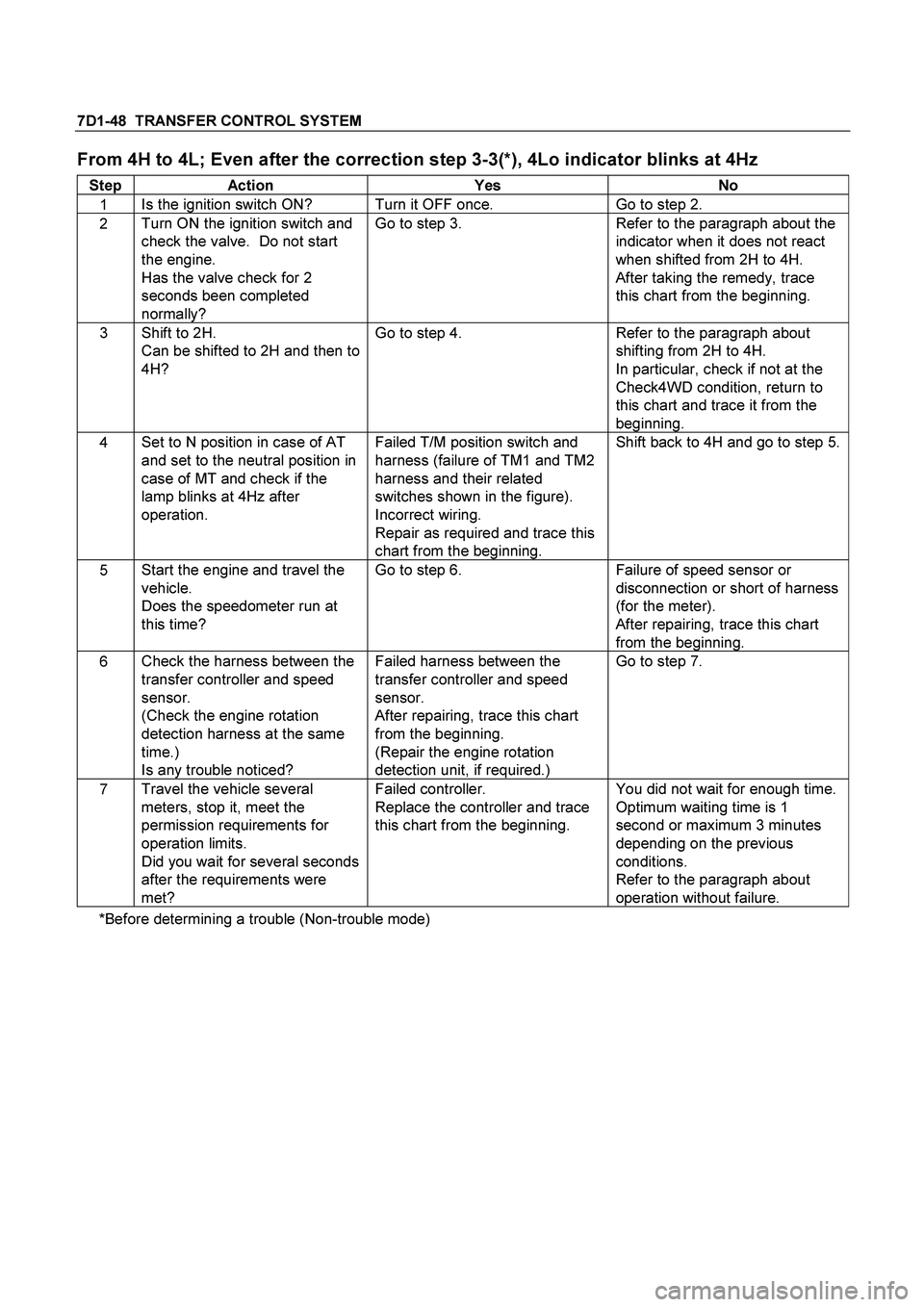
From 4H to 4L; Even after the correction step 3-3(*), 4Lo indicator blinks at 4Hz
Step Action Yes No
1 Is the ignition switch ON? Turn it OFF once. Go to step 2.
2 Turn ON the ignition switch and
check the valve. Do not start
the engine.
Has the valve check for 2
seconds been completed
normally? Go to step 3. Refer to the paragraph about the
indicator when it does not react
when shifted from 2H to 4H.
After taking the remedy, trace
this chart from the beginning.
3 Shift to 2H.
Can be shifted to 2H and then to
4H? Go to step 4. Refer to the paragraph about
shifting from 2H to 4H.
In particular, check if not at the
Check4WD condition, return to
this chart and trace it from the
beginning.
4 Set to N position in case of AT
and set to the neutral position in
case of MT and check if the
lamp blinks at 4Hz after
operation.
Failed T/M position switch and
harness (failure of TM1 and TM2
harness and their related
switches shown in the figure).
Incorrect wiring.
Repair as required and trace this
chart from the beginning. Shift back to 4H and go to step 5.
5 Start the engine and travel the
vehicle.
Does the speedometer run at
this time? Go to step 6. Failure of speed sensor or
disconnection or short of harness
(for the meter).
After repairing, trace this chart
from the beginning.
6 Check the harness between the
transfer controller and speed
sensor.
(Check the engine rotation
detection harness at the same
time.)
Is any trouble noticed? Failed harness between the
transfer controller and speed
sensor.
After repairing, trace this chart
from the beginning.
(Repair the engine rotation
detection unit, if required.) Go to step 7.
7 Travel the vehicle several
meters, stop it, meet the
permission requirements for
operation limits.
Did you wait for several seconds
after the requirements were
met? Failed controller.
Replace the controller and trace
this chart from the beginning. You did not wait for enough time.
Optimum waiting time is 1
second or maximum 3 minutes
depending on the previous
conditions.
Refer to the paragraph about
operation without failure.
*Before determining a trouble (Non-trouble mode)
Page 3675 of 4264
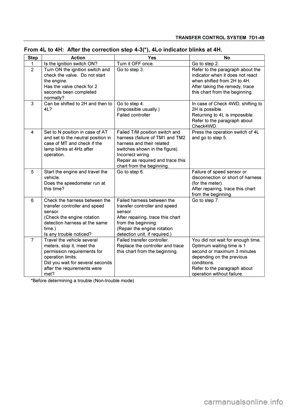
TRANSFER CONTROL SYSTEM 7D1-49
From 4L to 4H: After the correction step 4-3(*), 4Lo indicator blinks at 4H.
Step Action Yes No
1 Is the ignition switch ON? Turn it OFF once. Go to step 2.
2 Turn ON the ignition switch and
check the valve. Do not start
the engine.
Has the valve check for 2
seconds been completed
normally? Go to step 3. Refer to the paragraph about the
indicator when it does not react
when shifted from 2H to 4H.
After taking the remedy, trace
this chart from the beginning.
3 Can be shifted to 2H and then to
4L? Go to step 4.
(Impossible usually.)
Failed controller In case of Check 4WD, shifting to
2H is possible.
Returning to 4L is impossible.
Refer to the paragraph about
Check4WD.
4 Set to N position in case of AT
and set to the neutral position in
case of MT and check if the
lamp blinks at 4Hz after
operation.
Failed T/M position switch and
harness (failure of TM1 and TM2
harness and their related
switches shown in the figure).
Incorrect wiring.
Repair as required and trace this
chart from the beginning. Press the operation switch of 4L
and go to step 5.
5 Start the engine and travel the
vehicle.
Does the speedometer run at
this time? Go to step 6. Failure of speed sensor or
disconnection or short of harness
(for the meter).
After repairing, trace this chart
from the beginning.
6 Check the harness between the
transfer controller and speed
sensor.
(Check the engine rotation
detection harness at the same
time.)
Is any trouble noticed? Failed harness between the
transfer controller and speed
sensor.
After repairing, trace this chart
from the beginning.
(Repair the engine rotation
detection unit, if required.) Go to step 7.
7 Travel the vehicle several
meters, stop it, meet the
permission requirements for
operation limits.
Did you wait for several seconds
after the requirements were
met? Failed transfer controller.
Replace the controller and trace
this chart from the beginning. You did not wait for enough time.
Optimum waiting time is 1
second or maximum 3 minutes
depending on the previous
conditions.
Refer to the paragraph about
operation without failure.
*Before determining a trouble (Non-trouble mode)
Page 3676 of 4264
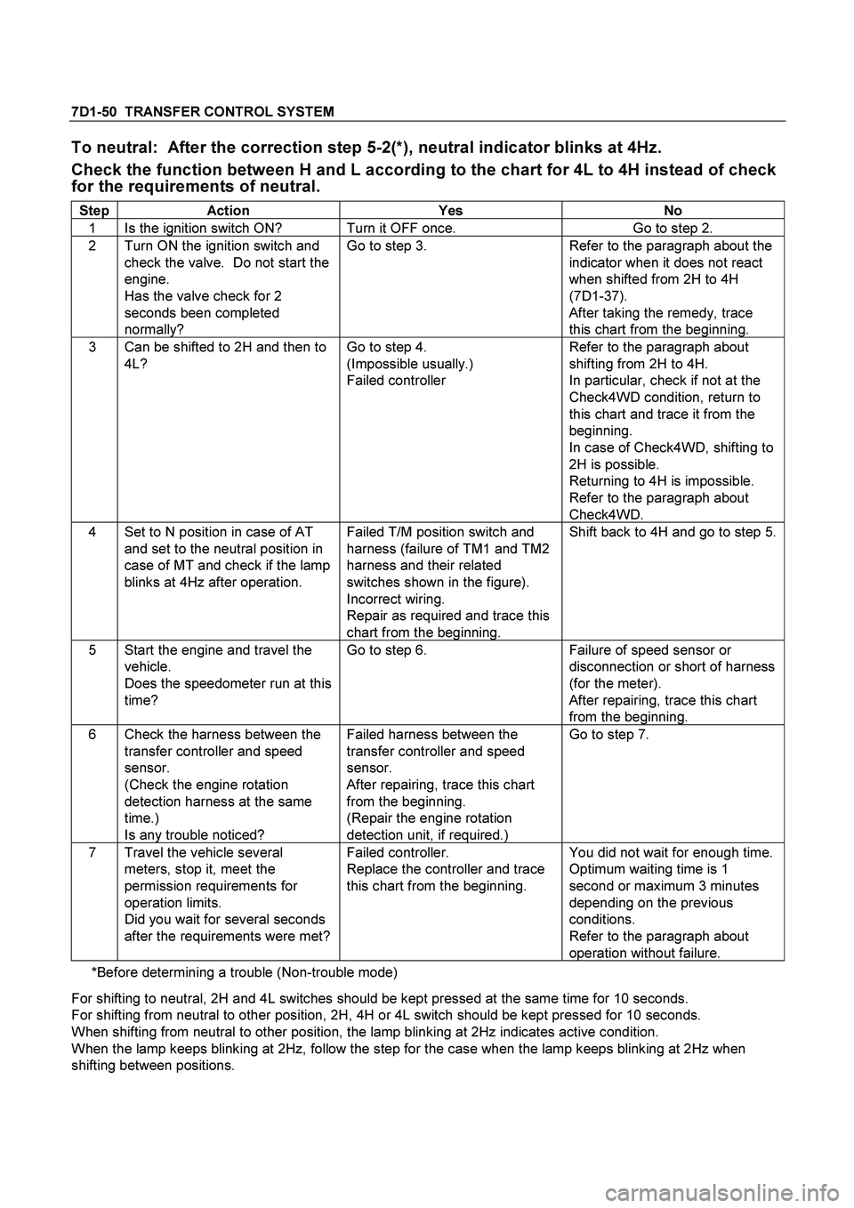
7D1-50 TRANSFER CONTROL SYSTEM
To neutral: After the correction step 5-2(*), neutral indicator blinks at 4Hz.
Check the function between H and L according to the chart for 4L to 4H instead of check
for the requirements of neutral.
Step Action Yes No
1 Is the ignition switch ON? Turn it OFF once. Go to step 2.
2 Turn ON the ignition switch and
check the valve. Do not start the
engine.
Has the valve check for 2
seconds been completed
normally? Go to step 3. Refer to the paragraph about the
indicator when it does not react
when shifted from 2H to 4H
(7D1-37).
After taking the remedy, trace
this chart from the beginning.
3 Can be shifted to 2H and then to
4L? Go to step 4.
(Impossible usually.)
Failed controller Refer to the paragraph about
shifting from 2H to 4H.
In particular, check if not at the
Check4WD condition, return to
this chart and trace it from the
beginning.
In case of Check4WD, shifting to
2H is possible.
Returning to 4H is impossible.
Refer to the paragraph about
Check4WD.
4 Set to N position in case of AT
and set to the neutral position in
case of MT and check if the lamp
blinks at 4Hz after operation. Failed T/M position switch and
harness (failure of TM1 and TM2
harness and their related
switches shown in the figure).
Incorrect wiring.
Repair as required and trace this
chart from the beginning. Shift back to 4H and go to step 5.
5 Start the engine and travel the
vehicle.
Does the speedometer run at this
time? Go to step 6. Failure of speed sensor or
disconnection or short of harness
(for the meter).
After repairing, trace this chart
from the beginning.
6 Check the harness between the
transfer controller and speed
sensor.
(Check the engine rotation
detection harness at the same
time.)
Is any trouble noticed? Failed harness between the
transfer controller and speed
sensor.
After repairing, trace this chart
from the beginning.
(Repair the engine rotation
detection unit, if required.) Go to step 7.
7 Travel the vehicle several
meters, stop it, meet the
permission requirements for
operation limits.
Did you wait for several seconds
after the requirements were met? Failed controller.
Replace the controller and trace
this chart from the beginning. You did not wait for enough time.
Optimum waiting time is 1
second or maximum 3 minutes
depending on the previous
conditions.
Refer to the paragraph about
operation without failure.
*Before determining a trouble (Non-trouble mode)
For shifting to neutral, 2H and 4L switches should be kept pressed at the same time for 10 seconds.
For shifting from neutral to other position, 2H, 4H or 4L switch should be kept pressed for 10 seconds.
When shifting from neutral to other position, the lamp blinking at 2Hz indicates active condition.
When the lamp keeps blinking at 2Hz, follow the step for the case when the lamp keeps blinking at 2Hz when
shifting between positions.
Page 3682 of 4264
7A2-2 TRANSMISSION CONTROL SYSTEM (AW30 –40LE) (V6 3.5L)
Service Precaution
WARNING: THIS VEHICLE HAS A SUPPLEMENTAL
RESTRAINT SYSTEM (SRS). REFER TO THE SRS
COMPONENT AND WIRING LOCATION VIEW IN
ORDER TO DETERMINE WHETHER YOU ARE
PERFORMING SERVICE ON OR NEAR THE SRS
COMPONENTS OR THE SRS WIRING. WHEN YOU
ARE PERFORMING SERVICE ON OR NEAR THE
SRS COMPONENTS OR THE SRS WIRING, REFE
R
TO THE SRS SERVICE INFORMATION. FAILURE TO
FOLLOW WARNINGS COULD RESULT IN
POSSIBLE AIR BAG DEPLOYMENT, PERSONAL
INJURY, OR OTHERWISE UNNEEDED SRS SYSTEM
REPAIRS.
CAUTION: Always use the correct fastener in the
proper location. When you replace a fastener, use
ONLY the exact part number for that application.
ISUZU will call out those fasteners that require a
replacement after removal. ISUZU will also call out
the fasteners that require thread lockers or thread
sealant. UNLESS OTHERWISE SPECIFIED, do not
use supplemental coatings (Paints, greases, o
r
other corrosion inhibitors) on threaded fasteners or
fastener joint interfaces. Generally, such coatings
adversely affect the fastener torque and the joint
clamping force, and may damage the fastener.
When you install fasteners, use the correct
tightening sequence and specifications. Following
these instructions can help you avoid damage to
parts and systems.
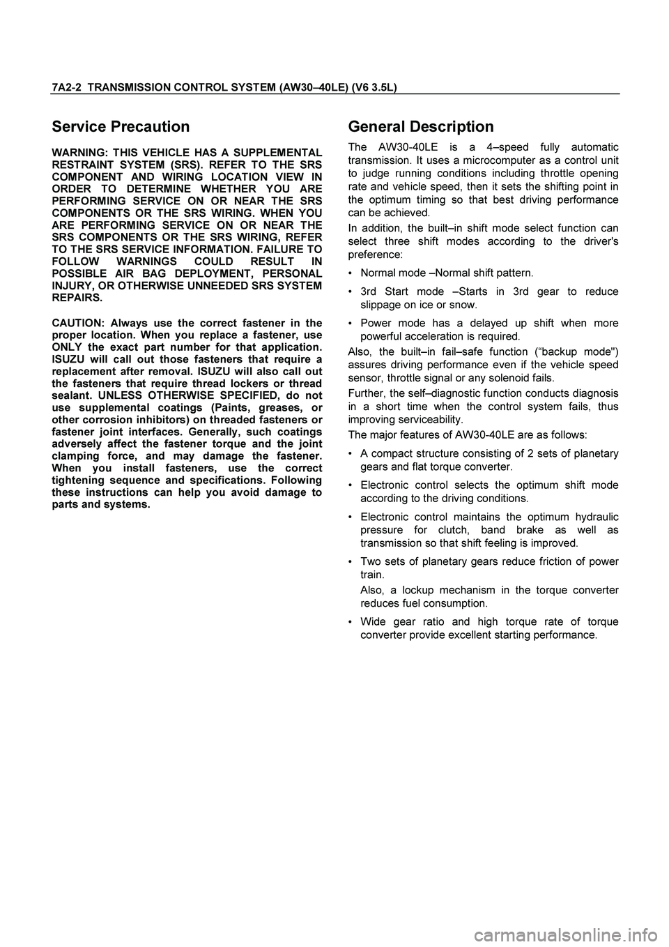
General Description
The AW30-40LE is a 4–speed fully automatic
transmission. It uses a microcomputer as a control unit
to judge running conditions including throttle opening
rate and vehicle speed, then it sets the shifting point in
the optimum timing so that best driving performance
can be achieved.
In addition, the built–in shift mode select function can
select three shift modes according to the driver's
preference:
Normal mode –Normal shift pattern.
3rd Start mode –Starts in 3rd gear to reduce
slippage on ice or snow.
Power mode has a delayed up shift when more
powerful acceleration is required.
Also, the built–in fail–safe function (“backup mode")
assures driving performance even if the vehicle speed
sensor, throttle signal or any solenoid fails.
Further, the self–diagnostic function conducts diagnosis
in a short time when the control system fails, thus
improving serviceability.
The major features of AW30-40LE are as follows:
A compact structure consisting of 2 sets of planetary
gears and flat torque converter.
Electronic control selects the optimum shift mode according to the driving conditions.
Electronic control maintains the optimum hydraulic
pressure for clutch, band brake as well as
transmission so that shift feeling is improved.
Two sets of planetary gears reduce friction of powe
r
train.
Also, a lockup mechanism in the torque converter
reduces fuel consumption.
Wide gear ratio and high torque rate of torque
converter provide excellent starting performance.
Page 3693 of 4264
TRANSMISSION CONTROL SYSTEM (AW30 –40LE) (V6 3.5L) 7A2-13
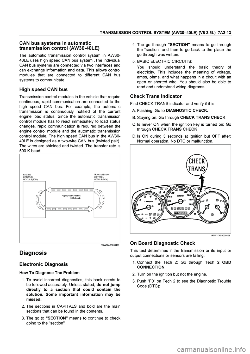
CAN bus systems in automatic
transmission control (AW30-40LE)
The automatic transmission control system in AW30-
40LE uses high speed CAN bus system .The individual
CAN bus systems are connected via two interfaces and
can exchange information and data. This allows control
modules that are connected to different CAN bus
systems to communicate.
High speed CAN bus
Transmission control modules in the vehicle that require
continuous, rapid communication are connected to the
high speed CAN bus. For example, the automatic
transmission is continuously notified of the current
engine load status. Since the automatic transmission
control module has to react immediately to load status
changes, rapid communication is required between the
engine control module and the automatic transmission
control module. The high speed CAN bus in the AW30-
40LE is designed as a two-wire CAN bus (twisted pair).
The wires are shielded and twisted. The transfer rate is
500 K baud.
RUW37ASF000401
Diagnosis
Electronic Diagnosis
How To Diagnose The Problem
1. To avoid incorrect diagnostics, this book needs to
be followed accurately. Unless stated, do not jump
directly to a section that could contain the
solution. Some important information may be
missed.
2. The sections in CAPITALS and bold are the main
sections that can be found in the contents.
3. The go to “
SECTION"
means to continue to check
going to the “section".
4. The go through “
SECTION"
means to go through
the “section" and then to go back to the place the
go through was written.
5. BASIC ELECTRIC CIRCUITS:
You should understand the basic theory o
f
electricity. This includes the meaning of voltage,
amps, ohms, and what happens in a circuit with an
open or shorted wire. You should also be able to
read and understand wiring diagrams.
Check Trans Indicator
Find CHECK TRANS indicator and verify if it is
A. Flashing: Go to DIAGNOSTIC CHECK.
B. Staying on: Go through CHECK TRANS CHECK
.
C. Is never ON when the ignition key is turned on: Go through CHECK TRANS CHECK
D. Is ON during 3 seconds at ignition but OFF after: Normal operation. No DTC or malfunction.
RTW37ASH000401
On Board Diagnostic Check
This test determines if the transmission or its input or
output connections or sensors are failing.
1. Connect the Tech 2: Go through Tech 2 OBD
CONNECTION .
2. Turn on the ignition but not the engine.
3. Push “F0" on Tech 2 to see the Diagnostic Trouble
Code (DTC):
Page 3716 of 4264
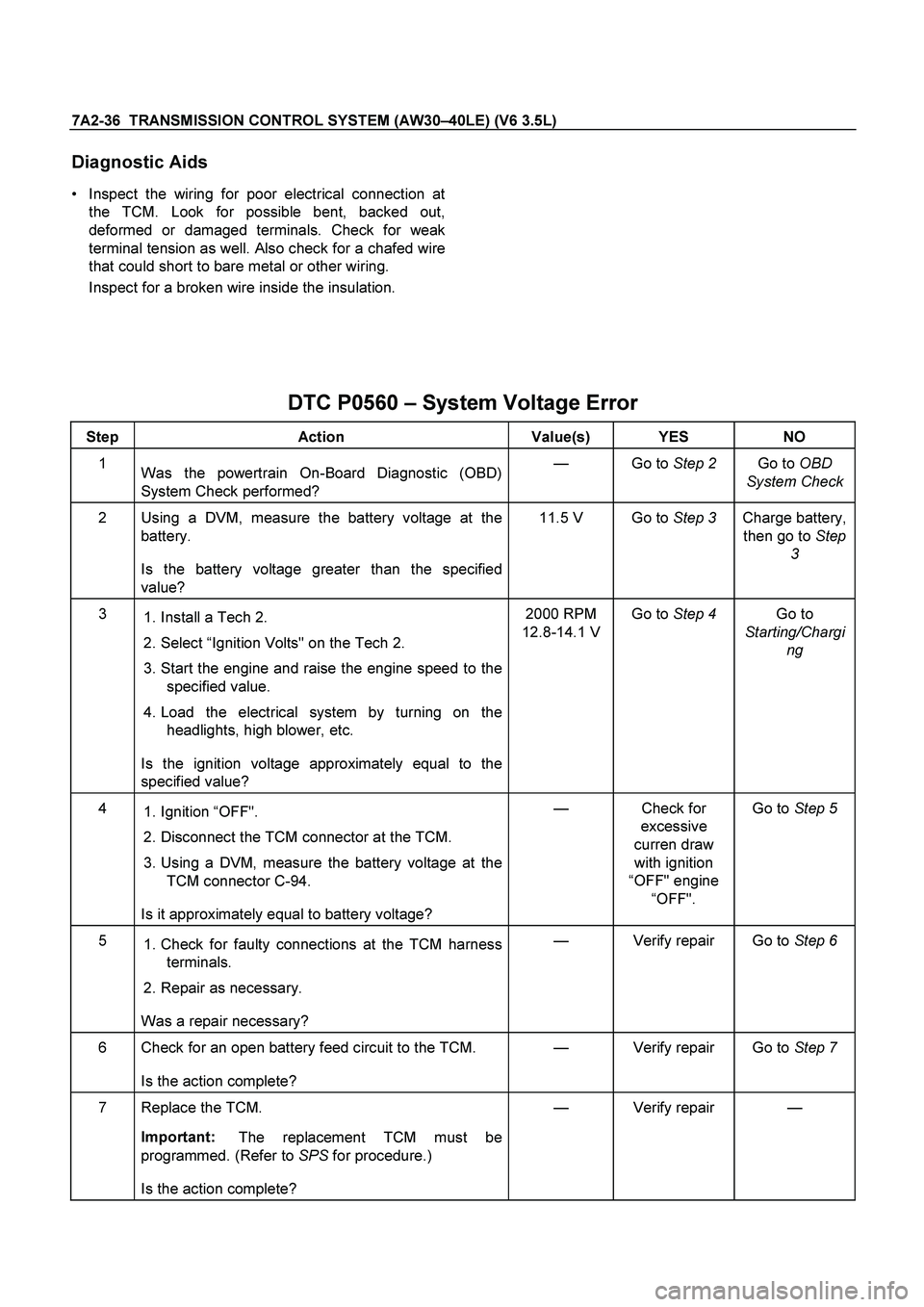
7A2-36 TRANSMISSION CONTROL SYSTEM (AW30–40LE) (V6 3.5L)
Diagnostic Aids
Inspect the wiring for poor electrical connection at
the TCM. Look for possible bent, backed out,
deformed or damaged terminals. Check for weak
terminal tension as well. Also check for a chafed wire
that could short to bare metal or other wiring.
Inspect for a broken wire inside the insulation.
DTC P0560 – System Voltage Error
Step Action Value(s) YES NO
1
Was the powertrain On-Board Diagnostic (OBD)
System Check performed? — Go to Step 2 Go to OBD
System Check
2 Using a DVM, measure the battery voltage at the
battery.
Is the battery voltage greater than the specified
value? 11.5 V Go to Step 3 Charge battery,
then go to Step
3
3
1. Install a Tech 2.
2. Select “Ignition Volts" on the Tech 2.
3. Start the engine and raise the engine speed to the
specified value.
4. Load the electrical system by turning on the
headlights, high blower, etc.
Is the ignition voltage approximately equal to the
specified value? 2000 RPM
12.8-14.1 VGo to Step 4 Go to
Starting/Chargi
ng
4
1. Ignition “OFF".
2. Disconnect the TCM connector at the TCM.
3. Using a DVM, measure the battery voltage at the
TCM connector C-94.
Is it approximately equal to battery voltage? — Check for
excessive
curren draw
with ignition
“OFF" engine
“OFF". Go to Step 5
5
1. Check for faulty connections at the TCM harness
terminals.
2. Repair as necessary.
Was a repair necessary? — Verify repair Go to Step 6
6 Check for an open battery feed circuit to the TCM.
Is the action complete? — Verify repair Go to Step 7
7 Replace the TCM.
Important:
The replacement TCM must be
programmed. (Refer to SPS for procedure.)
Is the action complete? — Verify repair —
Page 3720 of 4264
7A2-40 TRANSMISSION CONTROL SYSTEM (AW30–40LE) (V6 3.5L)
Condition 2 ("Short"):
When the TCM detects 2 times or more signals o
f
range sensor more than 0.025 sec at following
conditions.
Vehicle speed is more than 19 mph.
Engine speed is more than 1500 rpm.
Action Taken When The DTC Sets
No 3rd start mode.
No slope control.
The TCM judges always D range position of range
sensor at "Condition 1".
The TCM judges the position of range sensor with
following priority at "Condition 2".
There is a priority in order of D, 3, 2, L, R, N, and P.
Check Trans ON.
DTC stored.
Conditions For Clearing The DTC
The DTC can be cleared from the TCM history by
using a scan tool.
The DTC will be cleared from history when the
vehicle has achieved 40 warm-up cycles without a
failure reported.
After more than 1 second has elapsed after the
ignition key has been turned “ON", short between
No.11 and No.4 (ground) of DLC (Data Link
Connector). Then, after 1 second, but within 6
seconds, discontinue shorting.
Diagnostic Aids
Inspect the wiring for poor electrical connection at
the TCM. Look for possible bent, backed out,
deformed or damaged terminals. Check for weak
terminal tension as well. Also check for a chafed wire
that could short to bare metal or other wiring.
Inspect for a broken wire inside the insulation.
When diagnosing for a possible intermittent short o
r
open condition, move the wiring harness while
observing test equipment for a change.
Check range sensor for proper mounting and
adjustment.