Lead ISUZU TF SERIES 2004 Owner's Guide
[x] Cancel search | Manufacturer: ISUZU, Model Year: 2004, Model line: TF SERIES, Model: ISUZU TF SERIES 2004Pages: 4264, PDF Size: 72.63 MB
Page 1370 of 4264

6D – 32 ENGINE ELECTRICAL
MAGNETIC SWITCH
The following tests must be performed with the starter
motor fully assembled.
The yoke lead wire must be disconnected from the “M”
terminal.
To prevent coil burning, complete each test as quickly as
possible (within three to five seconds).
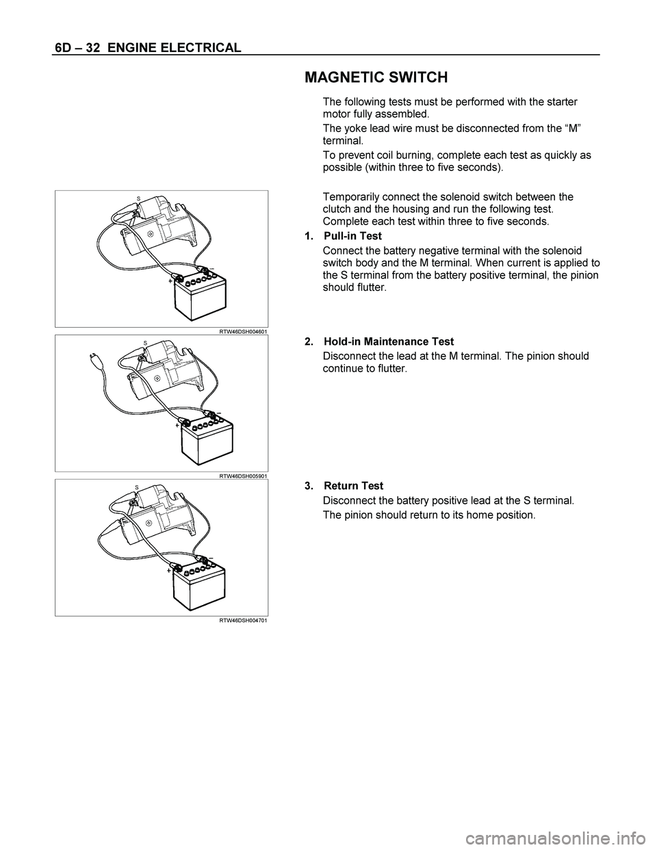
RTW46DSH004601
Temporarily connect the solenoid switch between the
clutch and the housing and run the following test.
Complete each test within three to five seconds.
1. Pull-in Test
Connect the battery negative terminal with the solenoid
switch body and the M terminal. When current is applied to
the S terminal from the battery positive terminal, the pinion
should flutter.
RTW46DSH005901
2. Hold-in Maintenance Test
Disconnect the lead at the M terminal. The pinion should
continue to flutter.
RTW46DSH004701
3. Return Test
Disconnect the battery positive lead at the S terminal.
The pinion should return to its home position.
Page 1436 of 4264

6E–64 4JA1/4JH1 ENGINE DRIVEABILITY AND EMISSIONS
GENERAL DESCRIPTION FOR ECM AND
SENSORS
Engine Control Module (ECM)
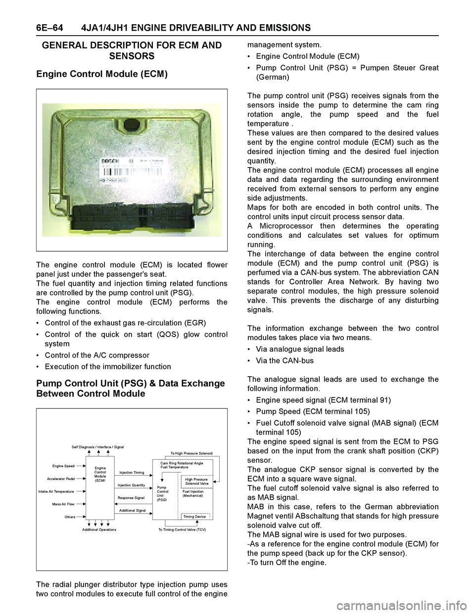
The engine control module (ECM) is located flower
panel just under the passenger's seat.
The fuel quantity and injection timing related functions
are controlled by the pump control unit (PSG).
The engine control module (ECM) performs the
following functions.
Control of the ex haust gas re-circulation (EGR)
Control of the quick on start (QOS) glow control
system
Control of the A/C compressor
Ex ecution of the immobilizer function
Pump Control Unit (PSG) & Data Exchange
Between Control Module
The radial plunger distributor type injection pump uses
two control modules to ex ecute full control of the enginemanagement system.
Engine Control Module (ECM)
Pump Control Unit (PSG) = Pumpen Steuer Great
(German)
The pump control unit (PSG) receives signals from the
sensors inside the pump to determine the cam ring
rotation angle, the pump speed and the fuel
temperature .
These values are then compared to the desired values
sent by the engine control module (ECM) such as the
desired injection timing and the desired fuel injection
quantity.
The engine control module (ECM) processes all engine
data and data regarding the surrounding environment
received from ex ternal sensors to perform any engine
side adjustments.
Maps for both are encoded in both control units. The
control units input circuit process sensor data.
A Microprocessor then determines the operating
conditions and calculates set values for optimum
running.
The interchange of data between the engine control
module (ECM) and the pump control unit (PSG) is
perfumed via a CAN-bus system. The abbreviation CAN
stands for Controller Area Network. By having two
separate control modules, the high pressure solenoid
valve. This prevents the discharge of any disturbing
signals.
The information ex change between the two control
modules takes place via two means.
Via analogue signal leads
Via the CAN-bus
The analogue signal leads are used to ex change the
following information.
Engine speed signal (ECM terminal 91)
Pump Speed (ECM terminal 105)
Fuel Cutoff solenoid valve signal (MAB signal) (ECM
terminal 105)
The engine speed signal is sent from the ECM to PSG
based on the input from the crank shaft position (CKP)
sensor.
The analogue CKP sensor signal is converted by the
ECM into a square wave signal.
The fuel cutoff solenoid valve signal is also referred to
as MAB signal.
MAB in this case, refers to the German abbreviation
Magnet ventil ABschaltung that stands for high pressure
solenoid v alv e cut off.
The MAB signal wire is used for two purposes.
-As a reference for the engine control module (ECM) for
the pump speed (back up for the CKP sensor).
-To turn Off the engine.
Sel f Dia gn osis / Interfa ce / Si gn al
To High Pressure Solenoid
Engine Speed
Injection Timing
Accelerator Pedal
Injection Quantity
In ta ke Air Temperat ure
Response Signal
Ma ss Air Flow
Additional Signal
Others
Additional Operations To Timing Control Valve (TCV)
Engin e
Con trol
Modu le
(ECM) Cam Rin g Rota tiona l Angle
Fuel Temper atu re
High Pressure
Solenoid Valve
Pump
Con tr ol Fuel Inject ion
Unit (Mechanical)
(PSG)
Ti m i n
g Devi ce
Page 1454 of 4264

6E–82 4JA1/4JH1 ENGINE DRIVEABILITY AND EMISSIONS
GENERAL SERVICE INFORMATION
Serviceability Issues
Non-OEM Parts
All of the OBD diagnostics have been calibrated to run
with OEM parts. Accordingly, if commercially sold
sensor or switch is installed, it makes a wrong diagnosis
and turns on the check engine lamp.
Aftermarket electronics, such as cellular phones,
stereos, and anti-theft devices, may radiate EMI into the
control system if they are improperly installed. This may
cause a false sensor reading and turn on the check
engine lamp.
Poor Vehicle Maintenance
The sensitivity of OBD diagnostics will cause the check
engine lamp to turn on if the vehicle is not maintained
properly. Restricted oil filters, fuel filters, and crankcase
deposits due to lack of oil changes or improper oil
viscosity can trigger actual vehicle faults that were not
previously monitored prior to OBD. Poor vehicle
maintenance can not be classified as a “non-vehicle
fault”, but with the sensitivity of OBD diagnostics,
vehicle maintenance schedules must be more closely
followed.
Related System Faults
Many of the OBD system diagnostics will not run if the
ECM detects a fault on a related system or component.
Visual/Physical Engine Compartment
Inspection
Perform a careful visual and physical engine
compartment inspection when performing any
diagnostic procedure or diagnosing the cause of an
emission test failure. This can often lead to repairing a
problem without further steps. Use the following
guidelines when performing a visual/physical
inspection:
Inspect all vacuum hoses for punches, cuts,
disconnects, and correct routing.
Inspect hoses that are difficult to see behind other
components.
Inspect all wires in the engine compartment for
proper connections, burned or chafed spots, pinched
wires, contact with sharp edges or contact with hot
exhaust manifolds or pipes.
Basic Knowledge of Tools Required
NOTE: Lack of basic knowledge of this powertrain
when performing diagnostic procedures could result in
an incorrect diagnosis or damage to powertrain
components. Do not attempt to diagnose a powertrain
problem without this basic knowledge.
A basic understanding of hand tools is necessary to
effectively use this section of the Service Manual.
ON-BOARD DIAGNOSTIC (OBD)
On-Board Diagnostic (Self Diagnosis
System) Tests
A diagnostic test is a series of steps, the result of which
is a pass or fail reported to the diagnostic ex ecutive.
When a diagnostic test reports a pass result, the
diagnostic ex ecutive records the following data:
The diagnostic test has been completed since the
last ignition cycle.
The diagnostic test has passed during the current
ignition cycle.
The fault identified by the diagnostic test is not
currently active.
When a diagnostic test reports a fail result, the
diagnostic ex ecutive records the following data:
The diagnostic test has been completed since the
last ignition cycle.
The fault identified by the diagnostic test is currently
active.
The fault has been active during this ignition cycle.
The operating conditions at the time of the failure.
The Diagnostic Executive
The Diagnostic Executive is a unique segment of
software which is designed to coordinate and prioritize
the diagnostic procedures as well as define the protocol
for recording and displaying their results. The main
responsibilities of the Diagnostic Ex ecutive are listed as
follow s:
Commanding the check engine lamp on and off
DTC logging and clearing
Current status information on each diagnostic
Diagnostic Information
The diagnostic charts and functional checks are
designed to locate a faulty circuit or component through
a process of logical decisions. The charts are prepared
with the requirement that the vehicle functioned
correctly at the time of assembly and that there are not
multiple faults present.
There is a continuous self-diagnosis on certain control
functions. This diagnostic capability is complemented
by the diagnostic procedures contained in this manual.
The language of communicating the source of the
malfunction is a system of diagnostic trouble codes.
When a malfunction is detected by the control module, a
diagnostic trouble code is set and the check engine
lamp is illuminated.
Check Engine Lamp
The check engine lamp looks the same as the check
engine lamp you are already familiar with, the “Check
Engine” lamp.
Basically, the check engine lamp is turned on when the
Page 1733 of 4264

4JA1/4JH1 ENGINE DRIVEABILITY AND EMISSIONS 6E–361
SYMPTOM DIAGNOSIS
PRELIMINARY CHECKS
Before using this section, perform the “On-Board
Diagnostic (OBD) System Check” and verify all of the
following items:
The engine control module (ECM) and check engine
lamp (MIL=malfunction indicator lamp are operating
correctly.
There are no Diagnostic Trouble Code(s) stored.
Tech 2 data is within normal operating range. Refer to
Typical Scan Data Values.
Verify the customer complaint and locate the correct
symptom in the table of contents. Perform the
procedure included in the symptom chart.
VISUAL/PHYSICAL CHECK
Several of the symptom procedures call for a careful
visual/physical check. This can lead to correcting a
problem without further checks and can save valuable
time. This check should include the following items:
ECM grounds for cleanliness, tightness and proper
location.
Vacuum hoses for splits, kinks, and proper
connection. Check thoroughly for any type of leak or
restriction.
Air intake ducts for collapsed or damaged areas.
Air leaks at throttle body mounting area, mass air flow
(MAF) sensor and intake manifold sealing surfaces.
Wiring for proper connections, pinches and cuts.
INTERMITTENT
Important: An intermittent problem may or may not turn
on the check engine lamp (MIL=malfunction indicator
lamp) or store a Diagnostic Trouble Code. Do NOT use
the Diagnostic Trouble Code (DTC) charts for
intermittent problems.
The fault must be present to locate the problem.
Most intermittent problems are cased by faulty electrical
connections or wiring. Perform a careful visual/physical
check for the following conditions.
Poor mating of the connector halves or a terminal not
fully seated in the connector (backed out).
Improperly formed or damaged terminal.
All connector terminals in the problem circuit should
be carefully checked for proper contact tension.
Poor terminal-to-wire connection. This requires
removing the terminal form the connector body to
check.
Check engine lamp (MIL=malfunction indicator lamp)
wire to ECM shorted to ground.
Poor ECM grounds. Refer to the ECM wiring
diagrams.Road test the vehicle with a Digital Multimeter
connected to a suspected circuit. An abnormal voltage
when the malfunction occurs is a good indication that
there is a fault in the circuit being monitored.
Using Tech 2 to help detect intermittent conditions. The
Tech 2 have several features that can be used to
located an intermittent condition. Use the following
features to find intermittent faults:
To check for loss of diagnostic code memory,
disconnect the MAF sensor and idle the engine until the
check engine lamp (MIL=malfunction indicator lamp)
comes on. Diagnostic Trouble Code P0100 should be
stored and kept in memory when the ignition is turned
OFF.
If not, the ECM is faulty. When this test is completed,
make sure that you clear the Diagnostic Trouble Code
P0100 from memory.
An intermittent check engine lamp (MIL=malfunction
indicator lamp) with no stored Diagnostic Trouble Code
may be caused by the following:
Check engine lamp (MIL=malfunction indicator lamp)
wire to ECM short to ground.
Poor ECM grounds. Refer to the ECM wiring
diagrams.
Check for improper installation of electrical options such
as light, cellular phones, etc. Check all wires from ECM
to the ignition control module for poor connections.
Check for an open diode across the A/C compressor
clutch and check for other open diodes (refer to wiring
diagrams in Electrical Diagnosis).
If problem has not been found, refer to ECM connector
symptom tables.
Check the “Broadcast Code” of the ECM, and
compare it with the latest Isuzu service bulletins and/
or Isuzu EEPROM reprogramming equipment to
determine if an update to the ECM's reprogrammable
memory has been released.
This identifies the contents of the reprogrammable
software and calibration contained in the ECM.
If the “Broadcast Code” is not the most current
available, it is advisable to reprogram the ECM's
EEPROM memory, which may either help identify a
hard-to find problem or may fix the problem.
The Service Programming System (SPS) will not allow
incorrect software programming or incorrect calibration
changes.
Page 1844 of 4264

6A-20 ENGINE MECHANICAL (6VE1 3.5L)
Malfunction Indicator Lamp
The instrument panel “CHECK ENGINE" Malfunction
Indicator Lamp (MIL) illuminates by self diagnostic
system when the system checks the starting of engine,
or senses malfunctions. ”CHECK ENGINE" MIL does
not illuminate at the starting of engine
Symptom Possible Cause Action
“CHECK ENGINE" MIL does not
illuminate at the starting of engine Bulb defective Replace
MIL circuit open Correct or replace
Command signal circuit to operate
self diagnostic system shorted Correct or replace
Engine Control Module (ECM) cable
loosely connected, disconnected or
defective Correct or replace
ECM defective Replace
“CHECK ENGINE" MIL illuminates,
and stays on Deterioration of heated oxygen
sensor internal element Replace
Heated oxygen sensor connector
terminal improper contact Reconnect properly
Heated oxygen sensor lead wire
shorted Correct
Heated oxygen sensor circuit open Correct or replace
Deterioration of engine coolant
temperature sensor internal element Replace
Engine coolant temperature sensor
connector terminal improper contact Reconnect properly
Engine coolant temperature sensor
lead wire shorted Correct
Engine coolant temperature sensor
circuit open Correct or replace
Throttle position sensor open or
shorted circuits Correct or replace
Deterioration of crankshaft position
sensor Replace
Crankshaft position sensor circuit
open or shorted Correct or replace
Vehicle speed sensor circuit open Correct or replace
Intake air temperature sensor circuit
open or shorted Correct or replace
Fuel injector circuit open or shorted Correct or replace
ECM driver transistor defective Replace ECM
Malfunctioning of ECM RAM
(Random Access Memory) or ROM
(Read Only Memory) Replace ECM
Page 1943 of 4264

ENGINE FUEL (6VE1 3.5L) 6C-1
ENGINE
ENGINE FUEL (6VE1 3.5L)
CONTENTS
Service Precaution................................................. 6C-1
General Description............................................... 6C-2
Fuel Metering.......................................................... 6C-3
Fuel Filter................................................................. 6C-4
Removal............................................................... 6C-4
Inspection............................................................. 6C-4
Installation............................................................ 6C-4
Inspection............................................................. 6C-4
In-Tank Fuel Filter............................................... 6C-4
Fuel Pump Flow Test......................................... 6C-4
Fuel Pump............................................................... 6C-6
Fuel Pump and Associated Parts..................... 6C-6
Removal............................................................... 6C-6
Installation............................................................ 6C-7
Fuel Tube / Quick - Connector Fittings............... 6C-8
Precautions.......................................................... 6C-8
Cautions During Work........................................ 6C-8
Removal................................................................ 6C-8
Reuse of Quick-Connector................................. 6C-9
Assembling Advice.............................................. 6C-9
Fuel Pump Relay..................................................... 6C-10
General Description............................................ 6C-10
Fuel Tank................................................................. 6C-11
Fuel Tank and Associated Parts....................... 6C-11
Removal................................................................ 6C-11
Installation............................................................. 6C-12
Filler Neck................................................................ 6C-13
Removal................................................................ 6C-13
Installation............................................................. 6C-13
Fuel Gauge Unit...................................................... 6C-13
Removal and Installation.................................... 6C-13
Fuel Filler Cap......................................................... 6C-14
General Description............................................ 6C-14
Inspection............................................................. 6C-14
Main Data and Specifications................................ 6C-15
Special Tool.......................................................... 6C-16
Service Precaution
When working on the fuel system, there are several
things to keep in mind:
Any time the fuel system is being worked on,
disconnect the negative battery cable except
for those tests where battery voltage is
required.
Always keep a dry chemical (Class B) fire
extinguisher near the work area.
Replace all pipes with the same pipe and
fittings that were removed.
Clean and inspect “O" rings. Replace i
f
required.
Always relieve the line pressure before
servicing any fuel system components.
Do not attempt repairs on the fuel system until
you have read the instructions and checked
the pictures relating to that repair.
Adhere to all Notices and Cautions.
All gasoline engines are designed to use only
unleaded gasoline. Unleaded gasoline must be
used for proper emission control system operation.
Its use will also minimize spark plug fouling and
extend engine oil life. Using leaded gasoline can
damage the emission control system and could
result in loss of emission warranty coverage.
All cars are equipped with an Evaporative Emission
Control System. The purpose of the system is to
minimize the escape of fuel vapors to the
atmosphere.
Page 1960 of 4264

6D1-2 ENGINE ELECTRICAL (6VE1 3.5L)
Battery
General Description
There are six battery fluid caps on the top of the battery.
These are covered by a paper label.
The battery is completely sealed except for the six small
vent holes on the side. These vent holes permit the
escape of small amounts of gas generated by the
battery.
This type of battery has the following advantages ove
r
conventional batteries:
1. There is no need to add water during the entire
service life of the battery.
2. The battery protects itself against overcharging.
The battery will refuse to accept an extensive
charge.
(A conventional battery will accept an excessive
charge, resulting in gassing and loss of battery
fluid.)
3. The battery is much less vulnerable to sel
f
discharge than a conventional type battery.
Diagnosis
1. Visual Inspection
Inspect the battery for obvious physical damage, such
as a cracked or broken case, which would permi
t
electrolyte loss.
Replace the battery if obvious physical damage is
discovered during inspection.
Check for any other physical damage and correct it as
necessary.
2. Fluid Level Check
The fluid level should be between the upper level line(1)
and lower level line(2) on side of battery.
a. CORRECT FLUID LEVEL – Charge the battery.
b. BELOW LOWER LEVEL – Replace battery.
RTW36DSH000101
3. Voltage Check
1. Put voltmeter test leads to battery terminals.
a. VOLTAGE IS 12.4V OR ABOVE – Go to Step 5.
b. VOLTAGE IS UNDER 12.4V – Go to procedure
(2) below.
2. Determine fast charge amperage from specification.
(See Main Data and Specifications in this section).
Fast charge battery for 30 minutes at amperage
rate no higher than specified value.
Take voltage and amperage readings after charge.
a. VOLTAGE IS ABOVE 16V AT BELOW 1/3 OF
AMPERAGE RATE – Replace battery.
b. VOLTAGE IS ABOVE 16V AT ABOVE 1/3 OF
AMPERAGE RATE – Drop charging voltage to
15V and charge for 10 – 15 hours. Then go to
Step 5.
c. VOLTAGE IS BETWEEN 12V AND 16V –
Continue charging at the same rate for an
additional 3–1/2 hours. Then go to Step 5.
d. VOLTAGE BELOW 12V – Replace Battery.
Page 1978 of 4264

6D3-6 STARTING AND CHARGING SYSTEM (6VE1 3.5L)
Disassembled View
065R100012
Legend (7) Housing
(1) Lead Wire (8) Over Running Clutch
(2) Through Bolt (9) Return Spring
(3) Yoke Assembly (10) Steel Ball
(4) Yoke Cover (11) Idle Pinion
(5) Brush and Brush Holder (12) Retainer
(6) Armature (13) Magnetic Switch
Page 1979 of 4264

STARTING AND CHARGING SYSTEM (6VE1 3.5L) 6D3-7
Disassembly
1. Remove the lead wire (1) from the magnetic switch.
2. Remove the through bolts (2).
065RY00053
Legend
(1) Lead Wire
(2) Through Bolt
3. Remove the yoke from the magnetic.
4. Remove the yoke cover.
5. Use the long nose pliers to remove the brush and
brush holder.
065RY00054
065RY00055
Legend
(1) Spring
(2) Brush
6. Remove the armature.
7. Remove the housing.
8. Remove the overrunning clutch from the housing.
065RY00056
Page 1983 of 4264

STARTING AND CHARGING SYSTEM (6VE1 3.5L) 6D3-11
Brush Spring
Use spring balancer to measure the spring setting force
when remove the spring from the brush.
Standard: 17.65–23.54 N (38.9–51.9 lb)
Limit: 11.77 N (25.9 lb)
Magnetic Switch
Temporarilly connect the magnetic switch between the
overrunning clutch and housing.
Perform the steps described below in 3 to 5 seconds.
1. Pull in test
Connect the ground (-) to terminal C and magnetic
switch body.
Verify that the pinion pulls out when the battery (+)
pole is connected to terminal 50.
065R100017
2. Hold in test
Observe that the pinion stays when the lead wire is
disconnected from terminal C.
065R100018
3. Return test
Connect the ground (-) to terminal 50 and magnetic
switch body.
Verify that the pinion pulls out when the battery (+)
pole is connected to terminal C and the pinion
pulls away when the lead wire is disconnected from
terminal 50.
065R100019
Field Coil
1. Check for continuity between the end of the field coil
and yoke body.
Replace the field coil, if there is continuity.
065RY00065