Timing ISUZU TF SERIES 2004 Owner's Guide
[x] Cancel search | Manufacturer: ISUZU, Model Year: 2004, Model line: TF SERIES, Model: ISUZU TF SERIES 2004Pages: 4264, PDF Size: 72.63 MB
Page 1381 of 4264
4JA1/4JH1 ENGINE DRIVEABILITY AND EMISSIONS 6E–9
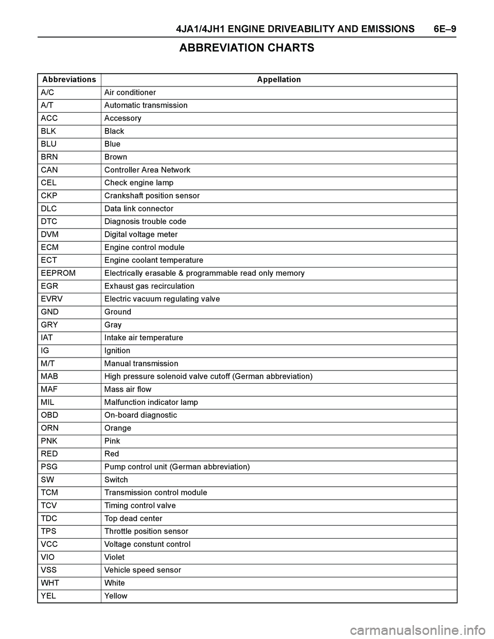
ABBREVIATION CHARTS
A bbreviations A ppellation
A/C Air conditioner
A/T Automatic transmission
ACC Accessory
BLK Black
BLU Blue
BRN Brown
CAN Controller Area Network
CEL Check engine lamp
CKP Crankshaft position sensor
DLC Data link connector
DTC Diagnosis trouble code
DVM Digital voltage meter
ECM Engine control module
ECT Engine coolant temperature
EEPROM Electrically erasable & programmable read only memory
EGR Ex haust gas recirculation
EVRV Electric vacuum regulating valve
GND Ground
GRY Gray
IAT Intake air temperature
IG Ignition
M/T Manual transmission
MAB High pressure solenoid valve cutoff (German abbreviation)
MAF Mass air flow
MIL Malfunction indicator lamp
OBD On-board diagnostic
ORN Orange
PNK Pink
RED Red
PSG Pump control unit (German abbreviation)
SW Switch
TCM Transmission control module
TCV Timing control valve
TDC Top dead center
TPS Throttle position sensor
VCC Voltage constunt control
VIO Violet
VSS Vehicle speed sensor
WHT Whi te
YEL Yellow
Page 1436 of 4264
6E–64 4JA1/4JH1 ENGINE DRIVEABILITY AND EMISSIONS
GENERAL DESCRIPTION FOR ECM AND
SENSORS
Engine Control Module (ECM)
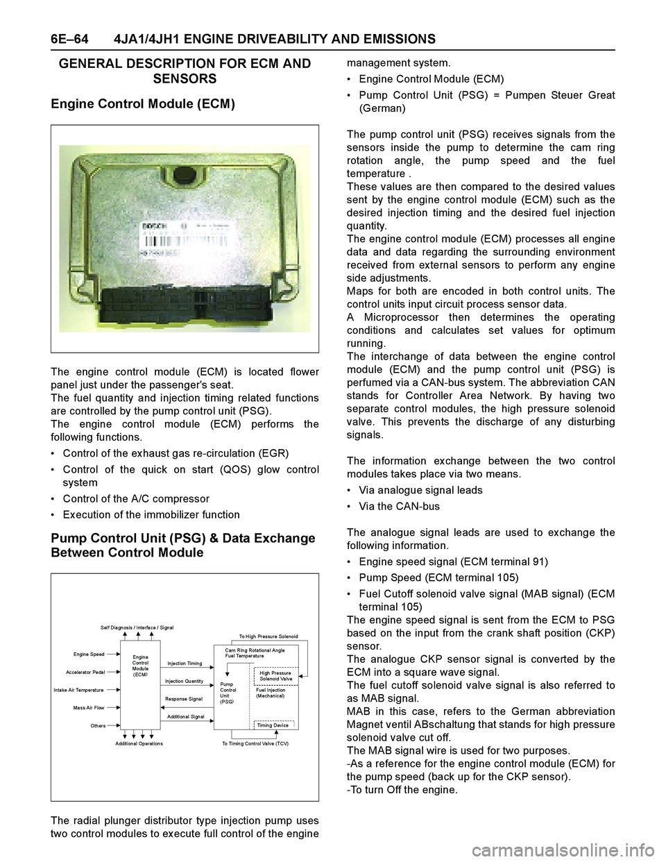
The engine control module (ECM) is located flower
panel just under the passenger's seat.
The fuel quantity and injection timing related functions
are controlled by the pump control unit (PSG).
The engine control module (ECM) performs the
following functions.
Control of the ex haust gas re-circulation (EGR)
Control of the quick on start (QOS) glow control
system
Control of the A/C compressor
Ex ecution of the immobilizer function
Pump Control Unit (PSG) & Data Exchange
Between Control Module
The radial plunger distributor type injection pump uses
two control modules to ex ecute full control of the enginemanagement system.
Engine Control Module (ECM)
Pump Control Unit (PSG) = Pumpen Steuer Great
(German)
The pump control unit (PSG) receives signals from the
sensors inside the pump to determine the cam ring
rotation angle, the pump speed and the fuel
temperature .
These values are then compared to the desired values
sent by the engine control module (ECM) such as the
desired injection timing and the desired fuel injection
quantity.
The engine control module (ECM) processes all engine
data and data regarding the surrounding environment
received from ex ternal sensors to perform any engine
side adjustments.
Maps for both are encoded in both control units. The
control units input circuit process sensor data.
A Microprocessor then determines the operating
conditions and calculates set values for optimum
running.
The interchange of data between the engine control
module (ECM) and the pump control unit (PSG) is
perfumed via a CAN-bus system. The abbreviation CAN
stands for Controller Area Network. By having two
separate control modules, the high pressure solenoid
valve. This prevents the discharge of any disturbing
signals.
The information ex change between the two control
modules takes place via two means.
Via analogue signal leads
Via the CAN-bus
The analogue signal leads are used to ex change the
following information.
Engine speed signal (ECM terminal 91)
Pump Speed (ECM terminal 105)
Fuel Cutoff solenoid valve signal (MAB signal) (ECM
terminal 105)
The engine speed signal is sent from the ECM to PSG
based on the input from the crank shaft position (CKP)
sensor.
The analogue CKP sensor signal is converted by the
ECM into a square wave signal.
The fuel cutoff solenoid valve signal is also referred to
as MAB signal.
MAB in this case, refers to the German abbreviation
Magnet ventil ABschaltung that stands for high pressure
solenoid v alv e cut off.
The MAB signal wire is used for two purposes.
-As a reference for the engine control module (ECM) for
the pump speed (back up for the CKP sensor).
-To turn Off the engine.
Sel f Dia gn osis / Interfa ce / Si gn al
To High Pressure Solenoid
Engine Speed
Injection Timing
Accelerator Pedal
Injection Quantity
In ta ke Air Temperat ure
Response Signal
Ma ss Air Flow
Additional Signal
Others
Additional Operations To Timing Control Valve (TCV)
Engin e
Con trol
Modu le
(ECM) Cam Rin g Rota tiona l Angle
Fuel Temper atu re
High Pressure
Solenoid Valve
Pump
Con tr ol Fuel Inject ion
Unit (Mechanical)
(PSG)
Ti m i n
g Devi ce
Page 1437 of 4264

4JA1/4JH1 ENGINE DRIVEABILITY AND EMISSIONS 6E–65
The following signals are ex changed via the CAN-bus:
From ECM to PSG
Desired injection quantity
Desired injection timing
Engine speed
From PSG to ECM
Fuel temperature
Pump speed
Cylinder identifier
Control pulse (actual injection quantity + actual
injection timing)
PSG status
Mass Air Flow (MAF) Sensor & Intake Air
Temperature (IAT) Sensor
The mass air flow (MAF) sensor is part of the intake air
system.
It is fitted between the air cleaner and turbocharger and
measure the mass air flowing into the engine.
The mass air flow (MAF) sensor uses a hot film element
to determine the amount of air flowing into the engine.
The mass air flow (MAF) sensor assembly consist of a
mass air flow (MAF) sensor element and an intake air
temperature sensor that are both ex posed to the air flow
to be measured.
The mass air flow (MAF) sensor element measures the
partial air mass through a measurement duct on the
sensor housing.
Using calibration, there is an ex trapolation to the entire
mass air flow to the engine.The IAT sensor is a thermistor. A temperature changes
the resistance value. And it changes voltage. In other
words it measures a temperature value. Low air
temperature produces a high resistance.
The ECM supplies 5 volts signal to the IAT sensor
through resisters in the ECM and measures the voltage.
The signal voltage will be high when the air temperature
is cold, and it will be low when the air temperature is
hot.
(1) Air Cleaner Case
(2) Mass Air Flow (MAF) & Intake Air Temperature
(IAT) Sensor
1 2
Characteristic of IAT Sensor -Reference-
10 100 1000 10000 100000
-30 -20 -10 0 10 20 30 40 50 60 70 80 90 100 110
Intake Air Temp. (deg. C) (Tech2 Reading)
Resistance (ohm) (Solid Line)
Page 1442 of 4264
6E–70 4JA1/4JH1 ENGINE DRIVEABILITY AND EMISSIONS
GENERAL DESCRIPTION FOR INJECTION
PUMP
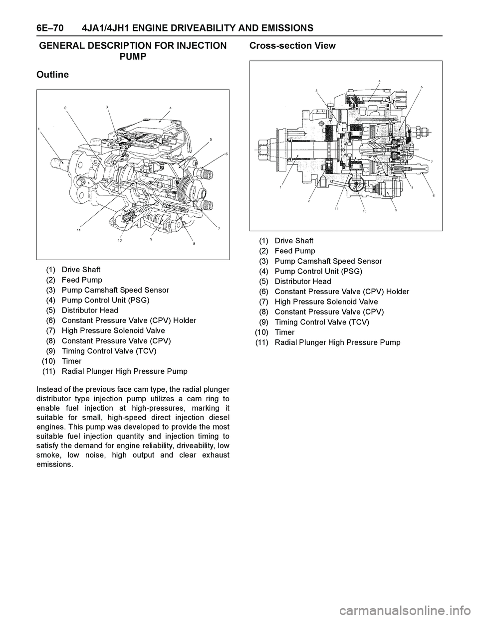
Outline
Instead of the previous face cam type, the radial plunger
distributor type injection pump utilizes a cam ring to
enable fuel injection at high-pressures, marking it
suitable for small, high-speed direct injection diesel
engines. This pump was developed to provide the most
suitable fuel injection quantity and injection timing to
satisfy the demand for engine reliability, driveability, low
smoke, low noise, high output and clear ex haust
emissions.
Cross-section View
(1) Drive Shaft
(2) Feed Pump
(3) Pump Camshaft Speed Sensor
(4) Pump Control Unit (PSG)
(5) Distributor Head
(6) Constant Pressure Valve (CPV) Holder
(7) High Pressure Solenoid Valve
(8) Constant Pressure Valve (CPV)
(9) Timing Control Valve (TCV)
(10) Timer
(11) Radial Plunger High Pressure Pump
(1) Drive Shaft
(2) Feed Pump
(3) Pump Camshaft Speed Sensor
(4) Pump Control Unit (PSG)
(5) Distributor Head
(6) Constant Pressure Valve (CPV) Holder
(7) High Pressure Solenoid Valve
(8) Constant Pressure Valve (CPV)
(9) Timing Control Valve (TCV)
(10) Timer
(11) Radial Plunger High Pressure Pump
Page 1444 of 4264
6E–72 4JA1/4JH1 ENGINE DRIVEABILITY AND EMISSIONS
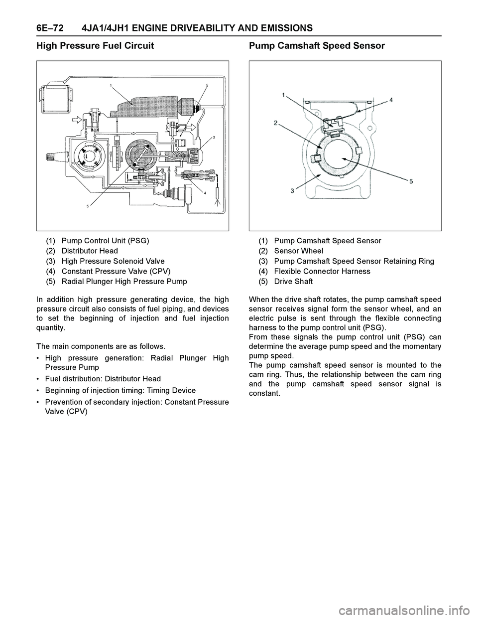
High Pressure Fuel Circuit
In addition high pressure generating device, the high
pressure circuit also consists of fuel piping, and devices
to set the beginning of injection and fuel injection
quantity.
The main components are as follows.
High pressure generation: Radial Plunger High
Pressure Pump
Fuel distribution: Distributor Head
Beginning of injection timing: Timing Device
Prevention of secondary injection: Constant Pressure
Valve (CPV)
Pump Camshaft Speed Sensor
When the drive shaft rotates, the pump camshaft speed
sensor receives signal form the sensor wheel, and an
electric pulse is sent through the flex ible connecting
harness to the pump control unit (PSG).
From these signals the pump control unit (PSG) can
determine the average pump speed and the momentary
pump speed.
The pump camshaft speed sensor is mounted to the
cam ring. Thus, the relationship between the cam ring
and the pump camshaft speed sensor signal is
constant. (1) Pump Control Unit (PSG)
(2) Distributor Head
(3) High Pressure Solenoid Valve
(4) Constant Pressure Valve (CPV)
(5) Radial Plunger High Pressure Pump
(1) Pump Camshaft Speed Sensor
(2) Sensor Wheel
(3) Pump Camshaft Speed Sensor Retaining Ring
(4) Flex ible Connector Harness
(5) Drive Shaft
Page 1445 of 4264
4JA1/4JH1 ENGINE DRIVEABILITY AND EMISSIONS 6E–73
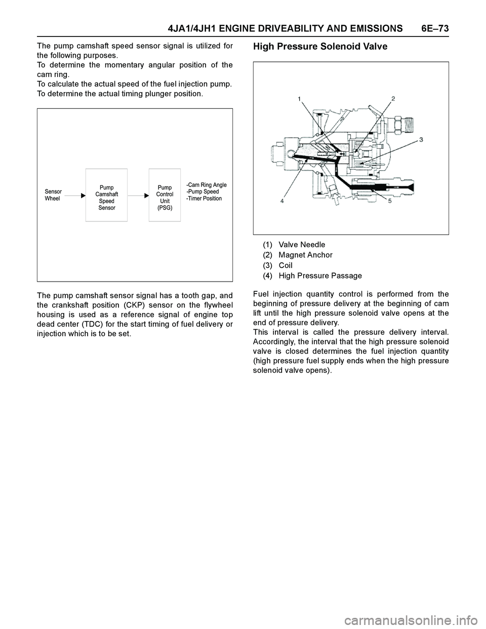
The pump camshaft speed sensor signal is utilized for
the following purposes.
To determine the momentary angular position of the
cam ring.
To calculate the actual speed of the fuel injection pump.
To determine the actual timing plunger position.
The pump camshaft sensor signal has a tooth gap, and
the crankshaft position (CKP) sensor on the flywheel
housing is used as a reference signal of engine top
dead center (TDC) for the start timing of fuel delivery or
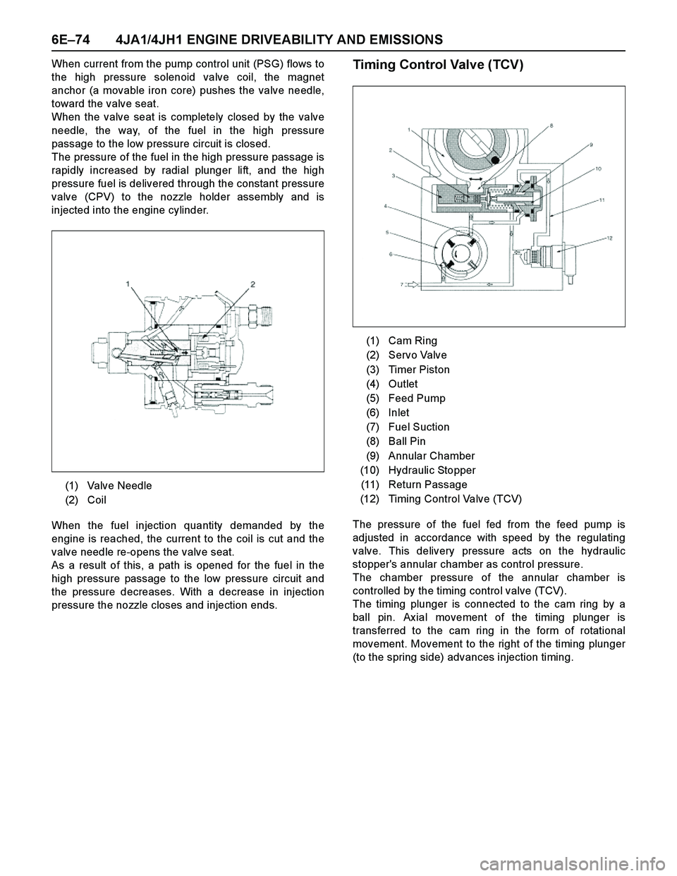
injection which is to be set.High Pressure Solenoid Valve
Fuel injection quantity control is performed from the
beginning of pressure delivery at the beginning of cam
lift until the high pressure solenoid valve opens at the
end of pressure delivery.
This interval is called the pressure delivery interval.
Accordingly, the interval that the high pressure solenoid
valve is closed determines the fuel injection quantity
(high pressure fuel supply ends when the high pressure
solenoid valve opens).
-Cam Ring Angle
Sensor -Pump Speed
Wheel -Timer PositionPump
Control
Unit
(PSG)Pump
Camshaft
Speed
Sensor
(1) Valve Needle
(2) Magnet Anchor
(3) Coil
(4) High Pressure Passage
Page 1446 of 4264
6E–74 4JA1/4JH1 ENGINE DRIVEABILITY AND EMISSIONS
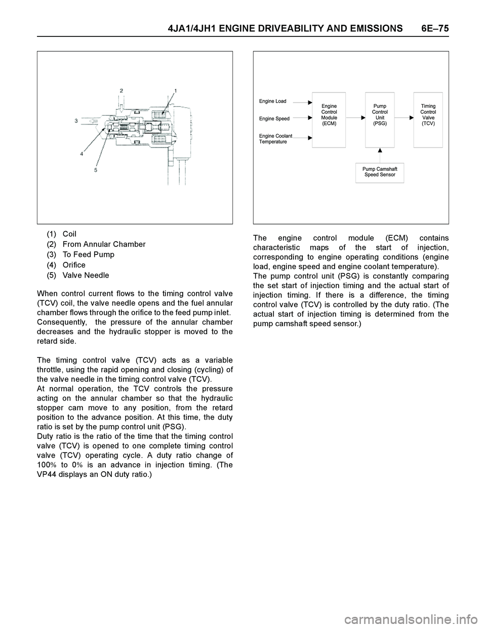
When current from the pump control unit (PSG) flows to
the high pressure solenoid valve coil, the magnet
anchor (a movable iron core) pushes the valve needle,
toward the valve seat.
When the valve seat is completely closed by the valve
needle, the way, of the fuel in the high pressure
passage to the low pressure circuit is closed.
The pressure of the fuel in the high pressure passage is
rapidly increased by radial plunger lift, and the high
pressure fuel is delivered through the constant pressure
valve (CPV) to the nozzle holder assembly and is
injected into the engine cylinder.
When the fuel injection quantity demanded by the
engine is reached, the current to the coil is cut and the
valve needle re-opens the valve seat.
As a result of this, a path is opened for the fuel in the
high pressure passage to the low pressure circuit and
the pressure decreases. With a decrease in injection
pressure the nozzle closes and injection ends.Timing Control Valve (TCV)
The pressure of the fuel fed from the feed pump is
adjusted in accordance with speed by the regulating
valve. This delivery pressure acts on the hydraulic
stopper's annular chamber as control pressure.
The chamber pressure of the annular chamber is
controlled by the timing control valve (TCV).
The timing plunger is connected to the cam ring by a
ball pin. Ax ial movement of the timing plunger is
transferred to the cam ring in the form of rotational
movement. Movement to the right of the timing plunger
(to the spring side) advances injection timing. (1) Valve Needle
(2) Coil
(1) Cam Ring
(2) Servo Valve
(3) Timer Piston
(4) Outlet
(5) Feed Pump
(6) Inlet
(7) Fuel Suction
(8) Ball Pin
(9) Annular Chamber
(10) Hydraulic Stopper
(11) Return Passage
(12) Timing Control Valve (TCV)
Page 1447 of 4264
4JA1/4JH1 ENGINE DRIVEABILITY AND EMISSIONS 6E–75
When control current flows to the timing control valve
(TCV) coil, the valve needle opens and the fuel annular
chamber flows through the orifice to the feed pump inlet.
Consequently, the pressure of the annular chamber
decreases and the hydraulic stopper is moved to the
retard side.
The timing control valve (TCV) acts as a variable
throttle, using the rapid opening and closing (cycling) of
the valve needle in the timing control valve (TCV).
At normal operation, the TCV controls the pressure
acting on the annular chamber so that the hydraulic
stopper cam move to any position, from the retard
position to the advance position. At this time, the duty
ratio is set by the pump control unit (PSG).
Duty ratio is the ratio of the time that the timing control
valve (TCV) is opened to one complete timing control
valve (TCV) operating cycle. A duty ratio change of
100% to 0% is an advance in injection timing. (The
VP44 displays an ON duty ratio.)The engine control module (ECM) contains
characteristic maps of the start of injection,
corresponding to engine operating conditions (engine
load, engine speed and engine coolant temperature).
The pump control unit (PSG) is constantly comparing
the set start of injection timing and the actual start of
injection timing. If there is a difference, the timing
control valve (TCV) is controlled by the duty ratio. (The
actual start of injection timing is determined from the
pump camshaft speed sensor.) (1) Coil
(2) From Annular Chamber
(3) To Feed Pump
(4) Orifice
(5) Valve Needle
Engine Load
Engine Speed
Engine Coolant
TemperatureEngine
Control
Module
(ECM)Pump
Control
Unit
(PSG)
Pump Camshaft
Speed Sensor
Timing
Control
Valve
(TCV)
Page 1460 of 4264
6E–88 4JA1/4JH1 ENGINE DRIVEABILITY AND EMISSIONS
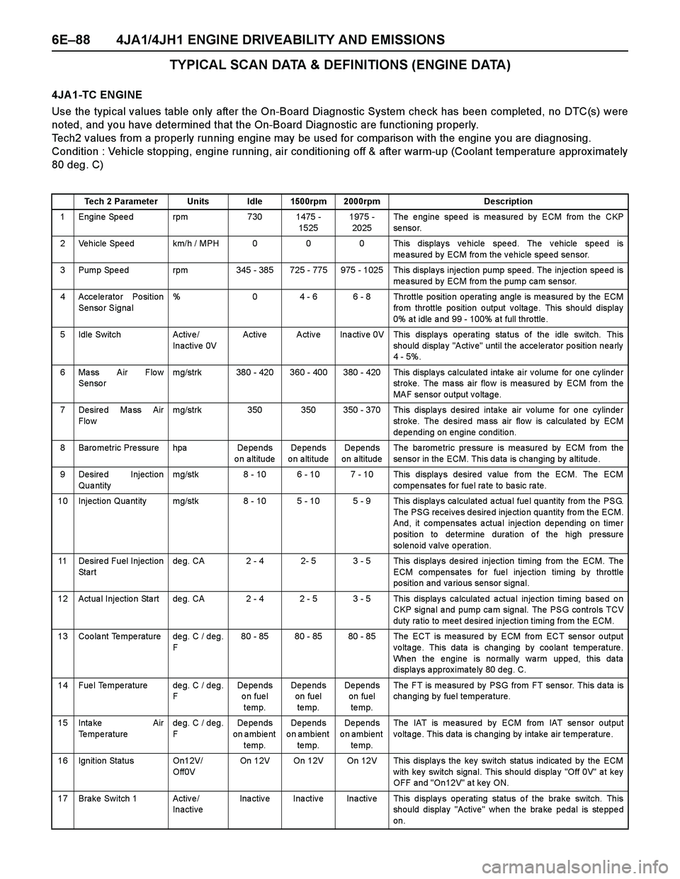
TYPICAL SCAN DATA & DEFINITIONS (ENGINE DATA)
4JA 1-TC ENGINE
Use the typical values table only after the On-Board Diagnostic System check has been completed, no DTC(s) were
noted, and you have determined that the On-Board Diagnostic are functioning properly.
Tech2 values from a properly running engine may be used for comparison with the engine you are diagnosing.
Condition : Vehicle stopping, engine running, air conditioning off & after warm-up (Coolant temperature approx imately
80 deg. C)
Tech 2 Parameter Units Idle 1500rpm 2000rpm Description
1 Engine Speed rpm 730 1475 -
15251975 -
2025The engine speed is measured by ECM from the CKP
se nso r.
2 Vehicle Speed km/h / MPH 0 0 0 This displays vehicle speed. The vehicle speed is
measured by ECM from the vehicle speed sensor.
3 Pump Spe ed rpm 345 - 385 725 - 775 975 - 1025 This displa ys injectio n pump spe ed. The inje ction spe ed is
measured by ECM from the pump cam sensor.
4 Accelerator Position
Sensor Signal% 0 4 - 6 6 - 8 Throttle position operating angle is measured by the ECM
fro m throttle po sition o utput v olta ge . This sho uld display
0% a t idle a nd 99 - 100% a t full thro ttle .
5 Idle Switch Activ e /
Inactive 0VActive Active Inactive 0V This displays operating status of the idle switch. This
should display "Active" until the accelerator position nearly
4 - 5%.
6 Mass Air Flow
Sensormg/strk 380 - 420 360 - 400 380 - 420 This displays calculated intake air volume for one cylinder
stroke. The mass air flow is measured by ECM from the
MAF sensor output voltage.
7 Desire d Ma ss Air
Flo wmg/strk 350 350 350 - 370 This displays desired intake air volume for one cylinder
stroke. The desired mass air flow is calculated by ECM
de pe nding on engine conditio n.
8 Baro metric Pre ssure hpa De pe nds
on altitudeDe pe nds
o n a ltitudeDe pe nds
on altitudeThe ba rome tric pre ssure is mea sure d by ECM from the
sensor in the ECM. This data is changing by altitude.
9 Desired Injection
Qua ntitymg/stk 8 - 10 6 - 10 7 - 10 This displays desired value from the ECM. The ECM
co mpe nsates fo r fue l ra te to ba sic ra te.
10 Injection Qua ntity mg/stk 8 - 10 5 - 10 5 - 9 This displa y s ca lculated a ctua l fue l qua ntity from the PSG.
The PSG receives desired injection quantity from the ECM.
And, it compensates actual injection depending on timer
po sitio n to de termine duration o f the high pre ssure
solenoid valve operation.
11 Desire d Fuel Injection
St a r tde g. CA 2 - 4 2- 5 3 - 5 This display s de sired injection timing from the ECM. The
ECM compensates for fuel injection timing by throttle
position and various sensor signal.
12 Actua l Injectio n Sta rt de g. CA 2 - 4 2 - 5 3 - 5 This display s ca lculate d a ctua l inje ctio n timing ba se d o n
CKP signa l a nd pump ca m signal. The PSG controls TCV
duty ra tio to mee t desired inje ctio n timing from the ECM.
13 Coolant Temperature deg. C / deg.
F80 - 85 80 - 85 80 - 85 The ECT is measured by ECM from ECT sensor output
voltage. This data is changing by coolant temperature.
When the engine is normally warm upped, this data
displays approximately 80 deg. C.
14 Fuel Temperature deg. C / deg.
FDe pe nds
on fuel
temp.De pe nds
on fuel
te mp.De pe nds
on fuel
te mp.The FT is measured by PSG from FT sensor. This data is
changing by fuel temperature.
15 Inta ke Air
Temperaturedeg. C / deg.
FDe pe nds
on ambient
temp.De pe nds
on ambient
te mp.De pe nds
on ambient
te mp.The IAT is measured by ECM from IAT sensor output
voltage. This data is changing by intake air temperature.
16 Ignition Status On12V/
Off0VOn 12V On 12V On 12V This displays the key switch status indicated by the ECM
with key switch signal. This should display "Off 0V" at key
OFF and "On12V" at key ON.
17 Brake Switch 1 Active/
InactiveInactive Inactive Inactive This displays operating status of the brake switch. This
should display "Active" when the brake pedal is stepped
on.
Page 1462 of 4264
6E–90 4JA1/4JH1 ENGINE DRIVEABILITY AND EMISSIONS
TYPICAL SCAN DATA & DEFINITIONS (ENGINE DATA)
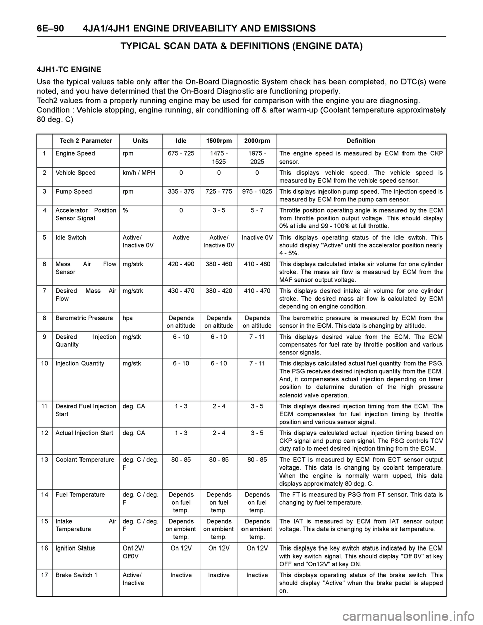
4JH1-TC ENGINE
Use the typical values table only after the On-Board Diagnostic System check has been completed, no DTC(s) were
noted, and you have determined that the On-Board Diagnostic are functioning properly.
Tech2 values from a properly running engine may be used for comparison with the engine you are diagnosing.
Condition : Vehicle stopping, engine running, air conditioning off & after warm-up (Coolant temperature approx imately
80 deg. C)
Tech 2 Parameter Units Idle 1500rpm 2000rpm Definition
1 Engine Speed rpm 675 - 725 1475 -
15251975 -
2025The engine speed is measured by ECM from the CKP
se nso r.
2 Vehicle Speed km/h / MPH 0 0 0 This displays vehicle speed. The vehicle speed is
measured by ECM from the vehicle speed sensor.
3 Pump Spe ed rpm 335 - 375 725 - 775 975 - 1025 This displa ys injectio n pump spe ed. The inje ction spe ed is
measured by ECM from the pump cam sensor.
4 Accelerator Position
Sensor Signal% 0 3 - 5 5 - 7 Throttle position operating angle is measured by the ECM
fro m throttle po sition o utput v olta ge . This sho uld display
0% a t idle a nd 99 - 100% a t full throttle .
5 Idle Switch Activ e /
Inactive 0VActive Active/
Inactive 0VInactive 0V This displays operating status of the idle switch. This
should display "Active" until the accelerator position nearly
4 - 5%.
6 Mass Air Flow
Sensormg/strk 420 - 490 380 - 460 410 - 480 This displays calculated intake air volume for one cylinder
stroke. The mass air flow is measured by ECM from the
MAF sensor output voltage.
7 Desire d Ma ss Air
Flo wmg/strk 430 - 470 380 - 420 410 - 470 This displays desired intake air volume for one cylinder
stroke. The desired mass air flow is calculated by ECM
de pe nding on engine conditio n.
8 Baro metric Pre ssure hpa De pe nds
on altitudeDe pe nds
o n a ltitudeDe pe nds
on altitudeThe ba rome tric pre ssure is mea sure d by ECM from the
sensor in the ECM. This data is changing by altitude.
9 Desired Injection
Qua ntitymg/stk 6 - 10 6 - 10 7 - 11 This displays desired value from the ECM. The ECM
co mpe nsates for fuel rate by thro ttle po sition a nd va rio us
se nso r signa ls.
10 Injection Qua ntity mg/stk 6 - 10 6 - 10 7 - 11 This displa y s ca lculated a ctua l fue l qua ntity from the PSG.
The PSG receives desired injection quantity from the ECM.
And, it compensates actual injection depending on timer
po sitio n to de termine duration o f the high pre ssure
solenoid valve operation.
11 Desire d Fuel Injection
St a r tde g. CA 1 - 3 2 - 4 3 - 5 This display s de sired injection timing from the ECM. The
ECM compensates for fuel injection timing by throttle
position and various sensor signal.
12 Actua l Injectio n Sta rt de g. CA 1 - 3 2 - 4 3 - 5 This display s ca lculate d a ctua l inje ctio n timing ba se d o n
CKP signa l a nd pump ca m signal. The PSG controls TCV
duty ra tio to mee t desired inje ctio n timing from the ECM.
13 Coolant Temperature deg. C / deg.
F80 - 85 80 - 85 80 - 85 The ECT is measured by ECM from ECT sensor output
voltage. This data is changing by coolant temperature.
When the engine is normally warm upped, this data
displays approximately 80 deg. C.
14 Fuel Temperature deg. C / deg.
FDe pe nds
on fuel
temp.De pe nds
on fuel
te mp.De pe nds
on fuel
te mp.The FT is measured by PSG from FT sensor. This data is
changing by fuel temperature.
15 Inta ke Air
Temperaturedeg. C / deg.
FDe pe nds
on ambient
temp.De pe nds
on ambient
te mp.De pe nds
on ambient
te mp.The IAT is measured by ECM from IAT sensor output
voltage. This data is changing by intake air temperature.
16 Ignition Status On12V/
Off0VOn 12V On 12V On 12V This displays the key switch status indicated by the ECM
with key switch signal. This should display "Off 0V" at key
OFF and "On12V" at key ON.
17 Brake Switch 1 Active/
InactiveInactive Inactive Inactive This displays operating status of the brake switch. This
should display "Active" when the brake pedal is stepped
on.