Timing ISUZU TF SERIES 2004 Service Manual
[x] Cancel search | Manufacturer: ISUZU, Model Year: 2004, Model line: TF SERIES, Model: ISUZU TF SERIES 2004Pages: 4264, PDF Size: 72.63 MB
Page 1488 of 4264

6E–116 4JA1/4JH1 ENGINE DRIVEABILITY AND EMISSIONS
52 P0215 A ON Fuel Cutoff Solenoid Valve
Malfunction1. Ignition key switch off.
2. Engine speed is below
1 5 0 0 r p m .
3. Vehicle speed is below
1 . 5 k m / h .
4. PSG (pump control unit)
recognizes MAB (fuel
cutoff solenoid valve)
signal from the ECM, but
the MAB could not
operate. 1. MAB (fuel cutoff solenoid
v a l v e ) i s o p e r a t e d .
2. Desired injection quantity
becomes 0mg/strk.No recovery until condition
match in the next ignition key
cycle.1. PSG (pump control unit)
m a l f u n c t i o n .
2. MAB (fuel cutoff solenoid
valve) malfunction.
——
B ON Fuel Cutoff Solenoid Valve
Circuit High InputECM does not command
MAB (fuel cutoff solenoid
valve) signal to the PSG
(pump control unit), but PSG
detected MAB signal line
circuit is high level.Engine does not start. No recovery. 1. MAB (fuel cutoff solenoid
valve) signal circuit short
t o v o l t a g e c i r c u i t .
2. PSG (pump control unit)
malfunction.105 —
C ON Fuel Cutoff Solenoid Valve
Always Active1. Ignition key switch off.
2. Engine speed is below
1 5 0 0 r p m .
3. Vehicle speed is below
1 . 5 k m / h .
4. PSG (pump control unit)
does not recognize MAB
(fuel cutoff solenoid
valve) signal from the
ECM. 1. MAB (fuel cutoff solenoid
v a l v e ) i s o p e r a t e d .
2. Desired injection quantity
becomes 0mg/strk.No recovery until condition
match in the next ignition key
cycle.1. MAB (fuel cutoff solenoid
valve) signal circuit open
or short to ground circuit.
2. PSG (pump control unit)
malfunction.
105 —
D ON Fuel Cutoff Solenoid Valve
Malfunction1. Ignition key switch off.
2. CAN controller does not
operate Bus-off.N o f a i l - s a f e f u n c t i o n . 1 . E C M m a l f u n c t i o n .
2. PSG (pump control unit)
malfunction.——
54 P0216 A ON Injection Timing Control
Circuit Malfunction1. Engine speed is more
t h a n 7 0 0 r p m .
2. Fuel injection quantity is
more than 4mg/stk.
3. Deviation of actual
injection timing and
desired injection timing is
more than +3 deg. CA or
-6 deg. CA for 8 seconds.Fuel injection quantity is
reduced.Deviation of actual injection
timing and desired injection
timing is more than +3 deg.
CA or -6 deg. CA for 8
seconds.1. Timing control valve
m a l f u n c t i o n .
2 . T i m e r p i s t o n s t i c k i n g .
3. Pump camshaft speed
sensor malfunction.——
B ON Injection Timing Control
Circuit Malfunction 1. Engine speed is more
t h a n 2 0 1 4 r p m .
2. Fluctuation of actual
injection timing is more
than +-5.2 deg. CA.1. Engine speed is more
than 2014rpm.
2. Fluctuation of actual
injection timing is more
than +-5.2 deg. CA.1. Insufficient air bleeding of
f u e l l i n e .
2. Fuel filter clogging.
3. Timing control valve
m a l f u n c t i o n .
4. Pump camshaft speed
sensor malfunction. —— Flash
CodeCodeSymptom
CodeMILDTC Name DTC Setting Condition Fail-Safe (Back Up) Recovery Condition Related Failure PartsRelated
ECM Pin
No.Related
Multiple
DTC4JA1-TC
(MT)4JH1-TC
(MT)4JH1-TC
(AT)
Page 1498 of 4264

6E–126 4JA1/4JH1 ENGINE DRIVEABILITY AND EMISSIONS
55 P1605 E ON EEPROM Defect EEPROM checksum does
not match with the read
check sum during
initialization of the ECM.EEPROM checksum match
with the read check sum
during initialization of the
ECM.ECM malfunction.
——
56 P1610 A - Security Key and Security
Code not ProgrammedImmobilizer functions are not
programmed in the ECM.1 . E n g i n e d o e s n o t s t a r t .
2. Check engine lamp flash. No recovery. ECM malfunction.
— B****
56 P1611 A - Wrong Security Code
EnteredReceived security code is not
correct.1 . E n g i n e d o e s n o t s t a r t .
2. Check engine lamp flash. N o r e c o v e r y . 1 . E C M m a l f u n c t i o n .
2. Immobilizer control unit
m a l f u n c t i o n .
3. Transponder key
malfunction.— B****
56 P1612 A - Immobilizer No or Wrong
SignalReceived challenge signal is
not correct or not received.1 . E n g i n e d o e s n o t s t a r t .
2. Check engine lamp flash. No recovery. 1. ECM and immobilizer
control unit
communication circuit
open circuit, short to
ground circuit or short to
voltage circuit.
2 . E C M m a l f u n c t i o n .
3. Immobilizer control unit
m a l f u n c t i o n .
4. Transponder key
malfunction.2 7 /
35B****
56 P1613 A - Immobilizer No or Wrong
SignalReceived response signal is
not correct or not received.1 . E n g i n e d o e s n o t s t a r t .
2. Check engine lamp flash. No recovery. 1. ECM and immobilizer
control unit
communication circuit
open circuit, short to
ground circuit or short to
voltage circuit.
2 . E C M m a l f u n c t i o n .
3. Immobilizer control unit
m a l f u n c t i o n .
4. Transponder key
malfunction.2 7 /
35B****
56 P1614 A - Wrong Transponder Key Received response signal is
not correct from the
transponder key.1 . E n g i n e d o e s n o t s t a r t .
2. Check engine lamp flash. N o r e c o v e r y . 1 . E C M m a l f u n c t i o n .
2. Immobilizer control unit
m a l f u n c t i o n .
3. Transponder key
malfunction.— B****
76 P1625 A OFF ECM Main Relay Switched
Off Too EarlyWhen ignition switch was
turned off, timing of the ECM
main relay turning off is too
early.No fail-safe function. No recovery. ECM malfunction.
3 /
58—
B OFF ECM Main Relay Switched
Off Too LateWhen ignition switch was
turned off, timing of the ECM
main relay turning off is too
late or does not off.No recovery. 1. ECM main relay
m a l f u n c t i o n .
2. ECM malfunction.3 /
58— Flash
CodeCodeSymptom
CodeMILDTC Name DTC Setting Condition Fail-Safe (Back Up) Recovery Condition Related Failure PartsRelated
ECM Pin
No.Related
Multiple
DTC4JA1-TC
(MT)4JH1-TC
(MT)4JH1-TC
(AT)
Page 1532 of 4264

6E–160 4JA1/4JH1 ENGINE DRIVEABILITY AND EMISSIONS
DIAGNOSTIC TROUBLE CODE (DTC) P0115 (SYMPTOM CODE 1)
(FLASH CODE 14) ENGINE COOLANT TEMPERATURE SENSOR CIRCUIT
HIGH INPUT
DIAGNOSTIC TROUBLE CODE (DTC) P0115 (SYMPTOM CODE 2)
(FLASH CODE 14) ENGINE COOLANT TEMPERATURE SENSOR CIRCUIT LOW
INPUT
Condition for setting the DTC and action taken when the DTC sets
Circuit Description
The ECT sensor is a thermistor. A temperature changesthe resistance value. And it changes voltage. In other
words it measures a temperature value. It is installed on
the coolant stream. Low coolant temperature produces
Flash
CodeCode Symptom
CodeMIL DTC Name DTC Setting Condition Fail-Safe (Back Up)
14 P0115 1 ON Engine Coolant Temperature
(ECT) Se nsor Circuit High
InputECT sensor output voltage is
more than 4.7V.1. ECM uses fue l te mpe rature
as substitute.
2. ECM uses 60 de g.C
condition for injection timing
contro l.
3. ECM uses -25 de g.C
condition (4JA1-TC) or -15
deg.C condition (4JH1-TC)
for glo w time co ntro l. 2 ON Engine Coolant Temperature
(ECT) Se nsor Circuit Low
InputECT sensor output voltage is
be lo w 0.3V.
Page 1550 of 4264

6E–178 4JA1/4JH1 ENGINE DRIVEABILITY AND EMISSIONS
DIAGNOSTIC TROUBLE CODE (DTC) P0216 (SYMPTOM CODE A) (FLASH
CODE 54) INJECTION TIMING CONTROL CIRCUIT MALFUNCTION
DIAGNOSTIC TROUBLE CODE (DTC) P0216 (SYMPTOM CODE B) (FLASH
CODE 54) INJECTION TIMING CONTROL CIRCUIT MALFUNCTION
Condition for setting the DTC and action taken when the DTC sets
Flash
CodeCode Symptom
CodeMIL DTC Name DTC Setting Condition Fail-Safe (Back Up)
54 P0216 A ON Inje ction Timing Co ntrol
Circuit Ma lfunction1. Engine speed is more
than 700rpm.
2. Fuel injection quantity is
more than 4mg/stk.
3. Deviation of actual
injection timing and
de sired inje ctio n timing is
more tha n +3 de g. CA or
-6 de g. CA for 8
se conds.Fuel inje ctio n qua ntity is
re duce d.
B ON Injection Timing Control
Circuit Ma lfunction 1. Engine speed is more
than 2014rpm.
2. Fluctuation of actual
inje ction timing is mo re
than +-5.2 deg. CA.
Page 1551 of 4264

4JA1/4JH1 ENGINE DRIVEABILITY AND EMISSIONS 6E–179
Circuit Description
The ECM is calculates an injection quantity and an
injection timing using the various sensors (crankshaft
position sensor, camshaft position sensor, engine
coolant temperature sensor, etc.). The timing control
valve (TCV) operation performs an injection timing
decision.
The TCV performs as a variable throttle, using the rapid
opening and closing cycle of the valve needle in the
TCV.
The TCV is assembled in the injection pump. The signal
of desired injection timing and actual injection timing are
ex changed via the CAN-bus between the PSG and
ECM.
If the timer position is out of tolerance (deviation or
fluctuation), DTC P0216 will be stored.
Diagnostic Aids
An intermittent may be caused by the following:
Poor connections.
Misrouted harness.
Rubbed through wire insulation.
Broken wire inside the insulation.
Insufficient air bleeding of fuel line.
Low fuel quantity in the fuel tank.
Check for the following conditions:
Insufficient air bleeding of fuel line inside, clogged
fuel filter or pinched fuel pipe/hose may cause the
DTC store or improper engine performance.Air bleeding procedure:
1.Operate the priming pump until strong resistance is
felt.
2.Wait 1 minute, and operate the priming pump until
strong resistance is felt.
3.Wait 1 minute, and operate the priming pump until
strong resistance is felt.
4.Turn the ignition switch to the "ON" position. Wait
until the glow indicator lamp turns off.
5.Turn the ignition switch to the "START" position and
crank the engine until it starts.
6.If the engine does not start, repeat Step 3 - 5.
7.Allow the engine to idle for 3 minutes to bleed air
completely form the fuel system and check for fuel
leakage.
Poor connection at ECM and PSG-Inspect harness
connectors for backed out terminals, improper
mating, broken locks, improperly formed or damaged
terminals, and poor terminal to wire connection.
Damaged harness-Inspect the wiring harness for
damage. If the harness appears to be OK, observe
the "Actual Injection Start" display on the Tech2 while
moving connectors and wiring harness related to the
sensor.
Page 1552 of 4264

6E–180 4JA1/4JH1 ENGINE DRIVEABILITY AND EMISSIONS
Diagnostic Trouble Code (DTC) P0216 (Symptom Code A) (Flash Code 54)
Injection Timing Control Circuit Malfunction
Diagnostic Trouble Code (DTC) P0216 (Symptom Code B) (Flash Code 54)
Injection Timing Control Circuit Malfunction
Step Action Value(s) Yes No
1 Was the "On-Board Diagnostic (OBD) System Check"
performed?
-Go to Step 2Go to On Board
Diagnostic
(OBD) System
Check
2 1. Connect the Tech 2.
2. Review and record the failure information.
3. Select "F0: Read DTC Infor As Stored By ECU" in
"F0: Diagnostic Trouble Codes".
Is the DTC P0216 (Symptom Code A) or P0216
(Symptom Code B) stored as "Present Failure"? - Go to Step 3Refer to
Diagnostic Aids
and Go to Step
3
3 1. 1Using the Tech 2, ignition "On" and engine "Off".
2. Select "F1: Clear DTC Information" in "F0:
Diagnostic Trouble Codes" with the Tech 2 and
c l e a r t h e D T C i n f o r m a t i o n .
3. Operate the vehicle and monitor the "F0: Read
DTC Infor As Stored By ECU" in the "F0:
Diagnostic Trouble Codes".
Was the DTC P0216 (Symptom Code A) or P0216
(Symptom Code B) stored in this ignition cycle? - Go to Step 4Refer to
Diagnostic Aids
and Go to Step
4
4 Perform the air bleeding in the fuel line sufficiently.
A ir Bleeding Procedure:
1. Operate the priming pump until strong resistance
is felt.
2. Wait 1 minute, and operate the priming pump until
strong resistance is felt.
3. Once more wait, and operate the priming pump
until strong resistance is felt.
4. Turn the ignition switch to the "ON" position. Wait
until the glow indicator lamp turns off.
5. Turn the ignition switch to the "START" position
and crank the engine until it starts.
6. If the engine does not start, repeat Step 3 - 5.
7. Allow the engine to idle for 3 minutes to bleed air
completely form the fuel system and check for fuel
leakage.
DTC Re-check:
1. Using the Tech 2, ignition "On" and engine "Off".
2. Select "F1: Clear DTC Information" in "F0:
Diagnostic Trouble Codes" with the Tech 2 and
c l e a r t h e D T C i n f o r m a t i o n .
3. Operate the vehicle and monitor the "F0: Read
DTC Infor As Stored By ECU" in the "F0:
Diagnostic Trouble Codes".
Was the DTC P0216 (Symptom Code A) or P0216
(Symptom Code B) restored in this ignition cycle? - Go to Step 5Verify repair
Page 1569 of 4264

4JA1/4JH1 ENGINE DRIVEABILITY AND EMISSIONS 6E–197
Condition for setting the DTC and action taken when the DTC sets
Circuit Description
The ECM is calculates an injection quantity and an
injection timing using the various sensors. And the PSG
controls the high pressure solenoid valve depending on
programmed pump map data.
The signal of desired injection quantity and actual injec-
tion quantify are ex changed via the CAN-bus between
the PSG and ECM.
If the relation of engine speed signal and doubled pump
camshaft speed signal ex cessively large, DTC P0251
(Symptom Code 7) will be stored.
If the CAN high or low circuit is defected, DTC P0251
(Symptom Code E) will be stored.
Diagnostic Aids
An intermittent may be caused by the following:
Poor connections.
Misrouted harness.
Rubbed through wire insulation.
Broken wire inside the insulation.
Check for the following conditions:
Poor connection at ECM and PSG-Inspect harness
connectors for backed out terminals, improper
mating, broken locks, improperly formed or damaged
terminals, and poor terminal to wire connection.
Damaged harness-Inspect the wiring harness for
damage. If the harness appears to be OK, observe
the “Injection Quantity” display on the Tech2 while
moving connectors and wiring harness related to the
sensor.
Diagnostic Trouble Code (DTC) P0251 (Symptom Code 6) (Flash Code 53)
Injection Pump Malfunction
Flash
CodeCode Symptom
CodeMIL DTC Name DTC Setting Condition Fail-Safe (Back Up)
53 P0251 6 ON Injection Pump Malfunction 1. No pump camshaft speed
se nsor erro r.
2. High pressure solenoid
v a lv e co ntro l pulse w idth
doe s no t ma tch with
desired fuel injection quan-
tity. 1. MAB (fuel cutoff solenoid
valve) is operated.
2. Desired injection quantity
becomes 0mg/strk.
7 ON Injection Pump Malfunction 1. No pump camshaft speed
se nsor erro r.
2. No CKP senso r e rror.
3. Difference of engine speed
and doubled pump cam-
shaft speed is more than
720rpm (4JA1-TC) or 690
rpm (4JH1-TC).
9 ON Injection Pump Malfunction No pump map programmed in
the PSG (pump co ntrol unit)
or PSG malfunction.
A ON Injection Pump Malfunction EEPROM or A/D converter
malfunctio n in the PSG (pump
control unit).Fuel inje ctio n qua ntity is
reduced.
B ON Injection Pump Malfunction PSG (pump control unit) rec-
ognized high pressure sole -
noid valve drive circuit error.No fa il-sa fe fun ctio n.
D ON Injection Pump Malfunction PSG (pump control unit) could
no t me asure the high pres-
sure solenoid valve drive volt-
age.
E ON Injection Pump Malfunction ECM could not accept PSG
(pump co ntrol unit) messa ge.1. MAB (fuel cutoff solenoid
valve) is operated.
2. Desired injection quantity
becomes 0mg/strk.
Step Action Value(s) Yes No
1Was the “On-Board Diagnostic (OBD) System Check”
performed?
—Go to Step 2Go to On Board
Diagnostic
(OBD) System
Check
Page 1709 of 4264

4JA1/4JH1 ENGINE DRIVEABILITY AND EMISSIONS 6E–337
DIAGNOSTIC TROUBLE CODE (DTC) P1625 (SYMPTOM CODE A)
(FLASH CODE 76) ECM MAIN RELAY SWITCHED OFF TOO EARLY
DIAGNOSTIC TROUBLE CODE (DTC) P1625 (SYMPTOM CODE B)
(FLASH CODE 76) ECM MAIN RELAY SWITCHED OFF TOO LATE
Condition for setting the DTC and action taken when the DTC sets
Circuit Description
The ECM switches ECM main relay to operate ECM
and other sensors or controller.
Diagnostic Aids
An intermittent may be caused by the following:
Poor connections.
Misrouted harness.
Rubbed through wire insulation.
Flash
CodeCode Symptom
CodeMIL DTC Name DTC Setting Condition Fail-Safe (Back Up)
76 P1625 A OFF ECM Main Relay Switche d
Off Too Ea rlyWhen ignition switch was
turne d off, timing of the ECM
main re la y turning off is to o
early.No fa il-sa fe fun ctio n.
B OFF ECM Main Relay Switched
Off Too LateWhen ignition switch was
turne d off, timing of the ECM
main re la y turning off is to o
late or does not off.
Page 1712 of 4264
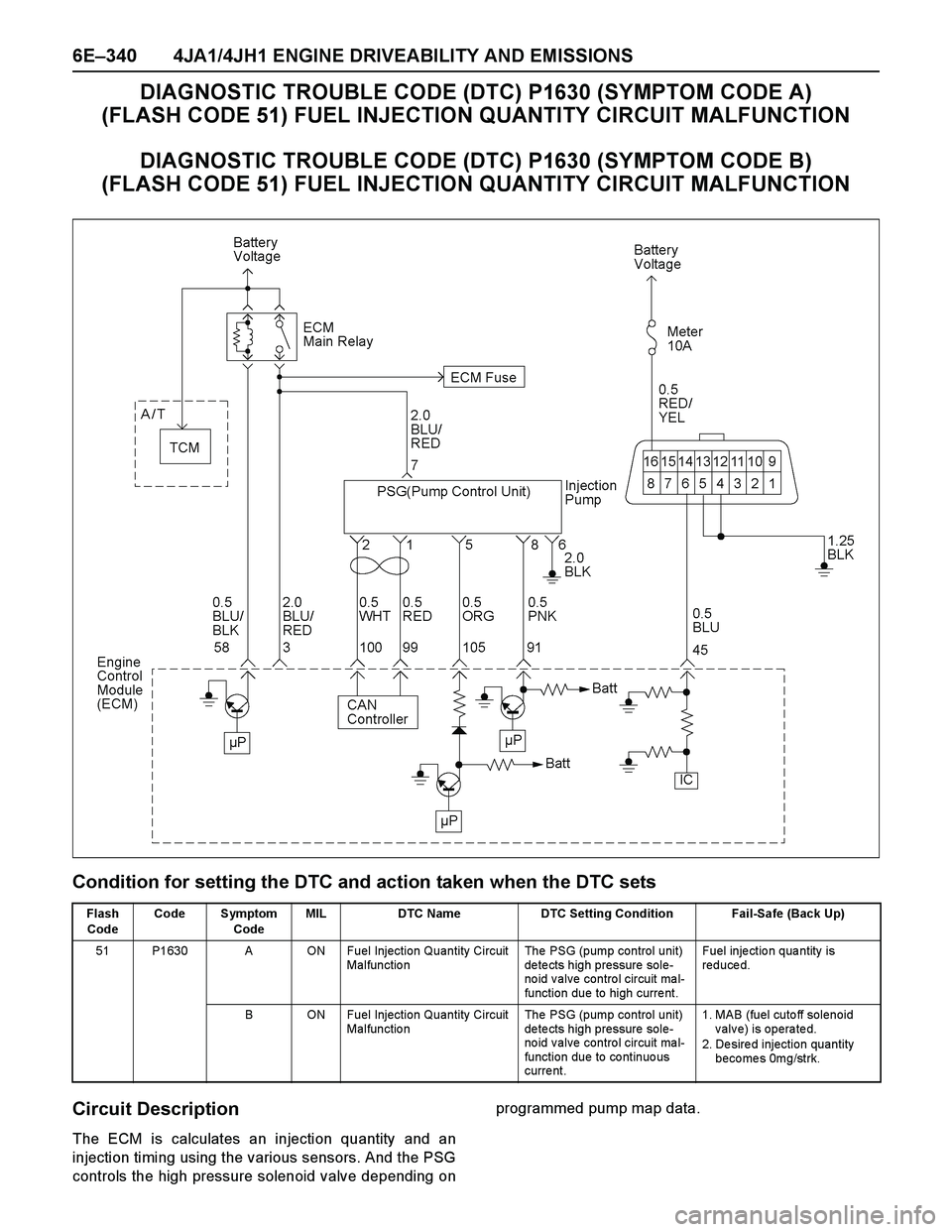
6E–340 4JA1/4JH1 ENGINE DRIVEABILITY AND EMISSIONS
DIAGNOSTIC TROUBLE CODE (DTC) P1630 (SYMPTOM CODE A)
(FLASH CODE 51) FUEL INJECTION QUANTITY CIRCUIT MALFUNCTION
DIAGNOSTIC TROUBLE CODE (DTC) P1630 (SYMPTOM CODE B)
(FLASH CODE 51) FUEL INJECTION QUANTITY CIRCUIT MALFUNCTION
Condition for setting the DTC and action taken when the DTC sets
Circuit Description
The ECM is calculates an injection quantity and an
injection timing using the various sensors. And the PSG
controls the high pressure solenoid valve depending onprogrammed pump map data.
Flash
CodeCode Symptom
CodeMIL DTC Name DTC Setting Condition Fail-Safe (Back Up)
51 P1630 A ON Fuel Injection Quantity Circuit
Malfunctio nThe PSG (pump control unit)
de te cts high pressure sole-
no id v alve contro l circuit ma l-
function due to high curre nt.Fuel inje ctio n qua ntity is
reduced.
B ON Fuel Injection Quantity Circuit
Malfunctio nThe PSG (pump control unit)
de te cts high pressure sole-
no id v alve contro l circuit ma l-
function due to co ntinuo us
curre nt.1. MAB (fuel cutoff solenoid
valve) is operated.
2. Desired injection quantity
becomes 0mg/strk.
Page 1736 of 4264

6E–364 4JA1/4JH1 ENGINE DRIVEABILITY AND EMISSIONS
17 Remove the eye bolt with gauze filter from the
injection pump and check for the following conditions.
Objects blocking at the gauze filter. Check for a
condition that causes contaminated fuel, such as
the customer is using an aftermarket fuel filter or
ex tended maintenance interval.
Check for a condition that causes fuel wax ing or
icing, such as the customer is using an incorrect
fuel type in winter season or water mix ed with the
fuel.
If a problem is found, repair as necessary.
Was the problem found?
—Replace the
eye bolt with
gauze filter and
verify repair Go to Step 18
18 Check the engine compression pressure for each
cylinders.
If a problem is found, repair as necessary.
Was the problem found?
More than 2.1
Mpa (21.0 kg/
cm
2) Verify repair Go to Step 19
19 If the injection pump was replaced, are the timing
gears or injection pump correctly installed?
—Go to Step 20Repair as
necessary Step Action Value(s) Yes No