differential ISUZU TFS SERIES 1997 User Guide
[x] Cancel search | Manufacturer: ISUZU, Model Year: 1997, Model line: TFS SERIES, Model: ISUZU TFS SERIES 1997Pages: 1600, PDF Size: 40.98 MB
Page 22 of 1600

4B-26 REAR AXLE
Important Operations
Prepare a side gear holder (An axle shaft must be used) as
shown in the left figure, clamp it with a stock vice, and set a
differential.
1. Bolt
Apply a setting mark to the differential cage cover and
differential cage a remove the bolt using the press.
W hen the differential cage is pressed down with the press,
loosen the four bolts fixing the differential cage evenly and
remove them, and then disconnect the differential cage.
Page 23 of 1600

REAR AXLE 4B-27
INSPECTION AND REPAIR
Make all necessary adjustments, repairs, and part replacements if wear, damage, or other problems are discovered
during inspection.
Gear
Bearing
Differential box
Drive pinion
Visual Check
Inspect the following parts for wear, damage or other abnormal
conditions.
Clearance between pinion gear and cross pin:
194 mm and 220 mm mm(in)
Standard Limit
0.06 - 0.12
(0.002 - 0.005)0.2 (0.008)
Clearance between side gear and differential cage.
mm(in)
Standard Limit
194 mm0.03 - 0.10
(0.001 - 0.004)0.15 (0.006)
220 mm0.05 - 0.11
(0.002 - 0.004)0.15 (0.006)
Play in splines between the side gear and axle shafts.
mm(in)
Standard Limit
194 mm 0.08 - 0.36 (0.003 - 0.014)
220 mm 0.08 - 0.38 (0.003 - 0.015)0.5 (0.02)
Page 24 of 1600

4B-28 REAR AXLE
Differential cage
Check the ring gear the side gear fitting faces and the cross pin
hole for scores or roughness. Correct as necessary. Slight
scores or roughness may be corrected with an oil stone or fine
sand paper.
Friction disc and plate assembly.
Check the parts for damage or other abnormal conditions.
Check the friction plate for distortion.
Limit mm(in) 0.07 (0.0027)
Check the friction plate for wear.
Limit (A - B) mm(in) 0.1 (0.0039)
Note : A = Non-sliding face thickness
B = Sliding face thickness
Check the friction disc for distortion.
Limit mm(in) 0.07 (0.0027)
Page 28 of 1600

4B-32 REAR AXLE
REASSEMBLY
MINOR COMPONENTS
LIMITED SLIP DIFFERENTIAL (LSD)
Reassembly Steps
1. Friction disc and plate
2. Disc spring
3. Spring plate
4. Sleeve
5. Differential cage
6. Friction disc and plate assembly
7. Side gear8. Friction disc and plate assembly
9. Side gear
10. Pinion gear
11. Pinion washer
12. Thrust block
13. Pinion shaft
14. Spring pin
Page 29 of 1600

REAR AXLE 4B-33
Important Operations
1. Friction disc and plate
Measure the thickness of disc and plate pack (A). mm(in)
Thickness (A) 7
0.1 (0.27 0.004)
If the thickness (A) is beyond the limits, adjust with a friction
disc of selected thickness.
Thickness of friction discs available mm(in)
1.4 (0.055), 1.5 (0.059)
Apply molybdenum disuffide grease to the friction discs and
plates.
3. Spring plate
Install the spring plate with dished side turned side turned to
the differential cage side.
10.Pinion gear
11.Pinion washer
(1) Clamp special tool (side gear holder) into a vise. Set the
LSD assembly.
Holder : 5-8840-2010-0
(J-36563)
(2) Set special tools (side pinion expanders and side pinion
rotator) to the LSD.
Expander : 5-8840-2011-0
(J-36564)
Rotator : 5-8840-2012-0
(J-36565)
Page 30 of 1600

4B-34 REAR AXLE
(3) Set special tool (cage lock bar) through a ring gear fixing
hole to a vice.
Then rotate side pinion expanders with a wrench one half to
one full turn to provide proper clearance to install the pinion
gears.
Bar : 5-8840-2013-0
(J-36566)
(4) Attach the pinion gears and washers in the proper order to
the left and right hand side of the differential cage.
(5) W ith a wrench, turn special tool (pinion rotator) to align the
pinion gear and washer holes with the pinion shaft holes on
the differential cage.
Confirmation of operation
Using the side gear holder, measure the starting of the side
gear.
Starting Torque N
m (kgfm/lbft)
Standard 147-225 (15 - 23/108 - 166)
Side gear holder : 5-8840-2010-0
(J-36563)
Side gear rotor : 5-8840-2012-0
(J-36565)
Page 31 of 1600

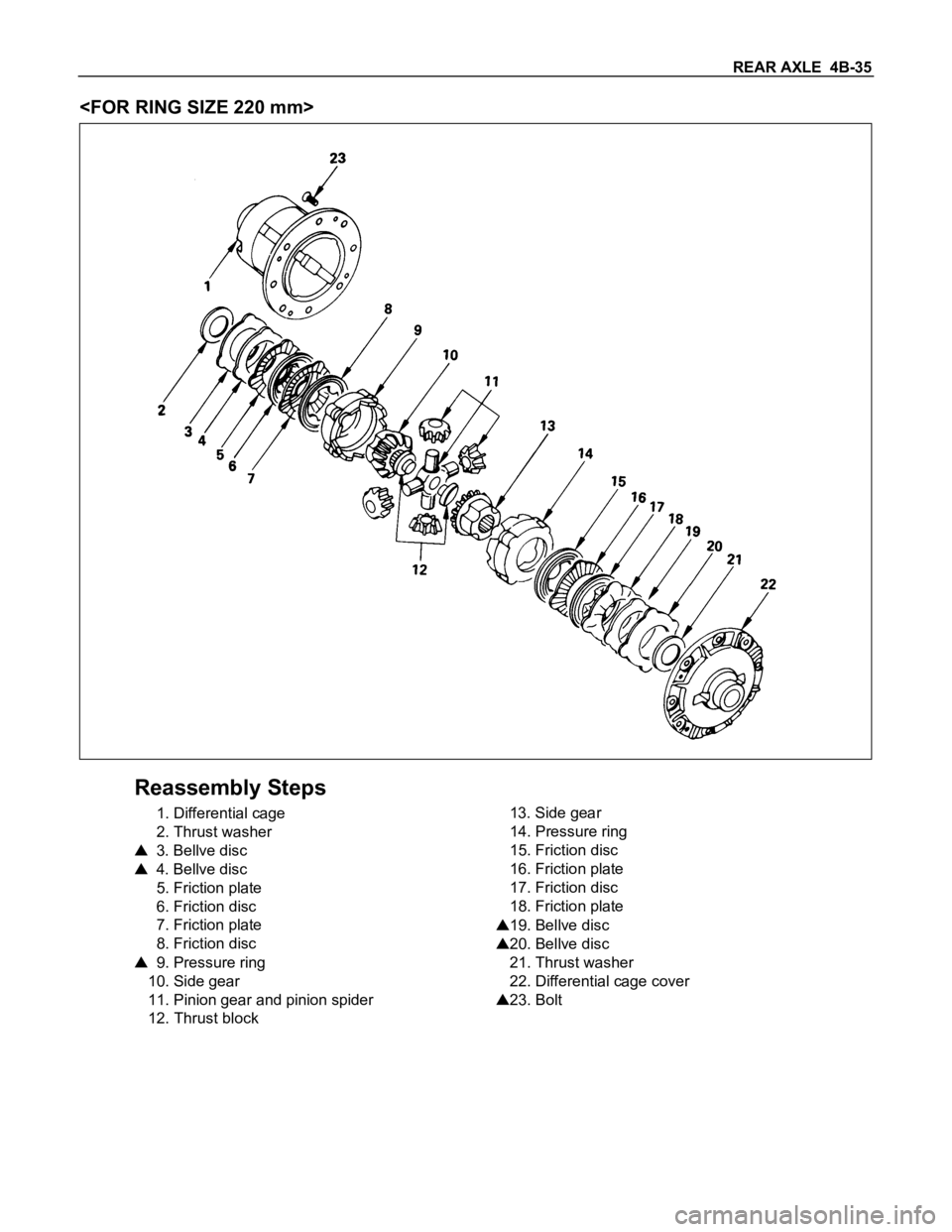
REAR AXLE 4B-35
Reassembly Steps
1. Differential cage
2. Thrust washer
3. Bellve disc
4. Bellve disc
5. Friction plate
6. Friction disc
7. Friction plate
8. Friction disc
9. Pressure ring
10. Side gear
11. Pinion gear and pinion spider
12. Thrust block13. Side gear
14. Pressure ring
15. Friction disc
16. Friction plate
17. Friction disc
18. Friction plate
19. Bellve disc
20. Bellve disc
21. Thrust washer
22. Differential cage cover
23. Bolt
Page 32 of 1600

4B-36 REAR AXLE
Adjustment of Clearance between
Friction Disc and Plate
1) Measuring depth of differential case
mm(in)
Standard (A-B) 80.58 (3.17)
(C) 10.58 (0.41)
2) Measuring overall length of pressure ring, friction disc and
plate assembly
Assembly pinion shaft with pressure ring, then friction
disc and plate.
Measure length between plates at both ends over V-
shape groove. (D)
3) After A, B, C and D dimensions are measured, perform
adjustment with the following procedure.
Measure disc spring :
1.75 mm (0.69 in)
2 pcs (E)
Measure thickness of plate spring
Standard dimension :
1.75 mm (0.069 in)
2 pcs (F)
4) Select a friction disc or plate so that ((A-B+C) - (D+E+F) =
0.06 to 0.20 mm (0.002 to 0.008 in.) and also the difference
in total dimension of friction disc and plate, plate spring and
disc spring (left/right side) does not exceed 0.05 mm (0.002
in.).
Thickness : 1.75, 1.85 mm
Adjusting Backlash of Side Gear in Axial
Direction
1) Measuring depth of differential case
mm(in.)
Standard (F-B) 82.03 (3.23)
(G) 12.03 (0.47)
Page 33 of 1600

REAR AXLE 4B-37
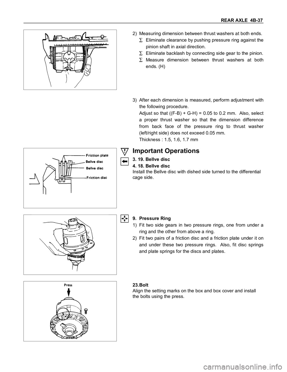
2) Measuring dimension between thrust washers at both ends.
Eliminate clearance by pushing pressure ring against the
pinion shaft in axial direction.
Eliminate backlash by connecting side gear to the pinion.
Measure dimension between thrust washers at both
ends. (H)
3) After each dimension is measured, perform adjustment with
the following procedure.
Adjust so that ((F-B) + G-H) = 0.05 to 0.2 mm. Also, select
a proper thrust washer so that the dimension difference
from back face of the pressure ring to thrust washer
(left/right side) does not exceed 0.05 mm.
Thickness : 1.5, 1.6, 1.7 mm
Important Operations
3. 19. Bellve disc
4. 18. Bellve disc
Install the Bellve disc with dished side turned to the differential
cage side.
9. Pressure Ring
1) Fit two side gears in two pressure rings, one from under a
ring and the other from above a ring.
2) Fit two pairs of a friction disc and a friction plate under it on
and under these two pressure rings. Also, fit disc springs
and plate springs for the discs and plates.
23.Bolt
Align the setting marks on the box and box cover and install
the bolts using the press.
Page 35 of 1600

REAR AXLE 4B-39
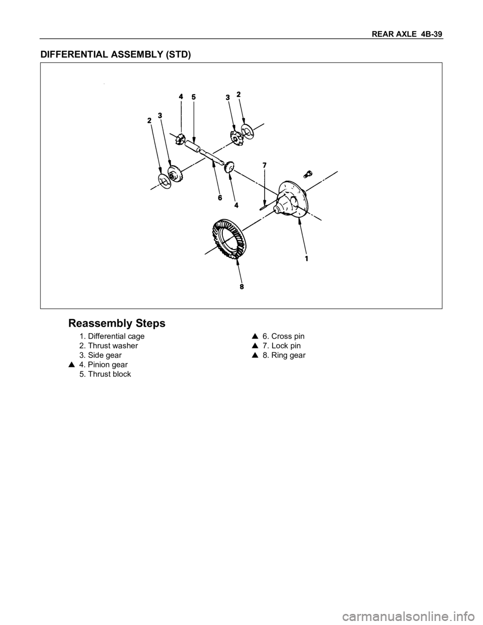
DIFFERENTIAL ASSEMBLY (STD)
Reassembly Steps
1. Differential cage
2. Thrust washer
3. Side gear
4. Pinion gear
5. Thrust block
6. Cross pin
7. Lock pin
8. Ring gear