torque ISUZU TFS SERIES 1997 Owner's Guide
[x] Cancel search | Manufacturer: ISUZU, Model Year: 1997, Model line: TFS SERIES, Model: ISUZU TFS SERIES 1997Pages: 1600, PDF Size: 40.98 MB
Page 123 of 1600
4C1-60 FRONT WHEEL DRIVE
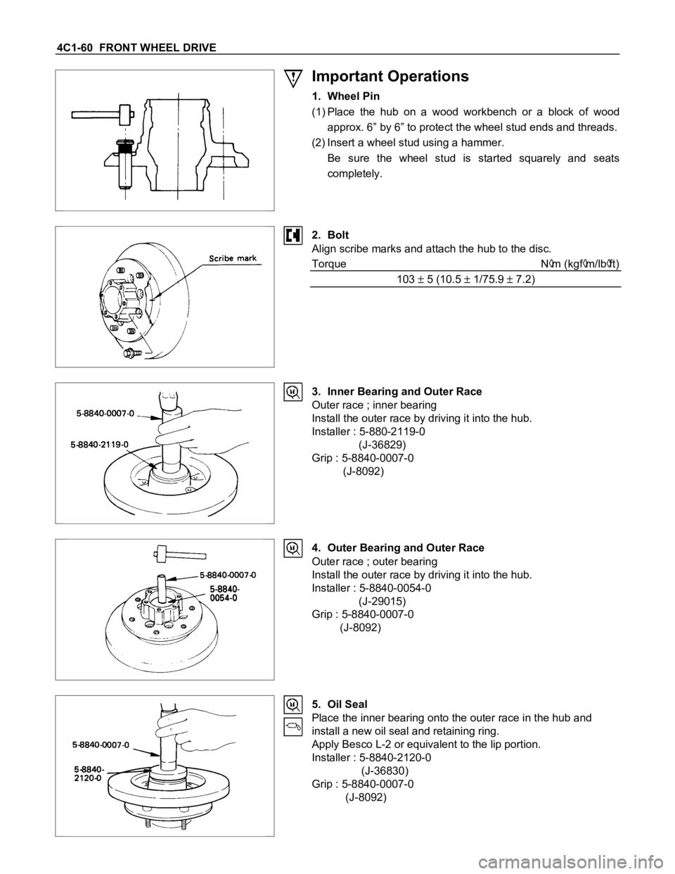
Important Operations
1. Wheel Pin
(1) Place the hub on a wood workbench or a block of wood
approx. 6” by 6” to protect the wheel stud ends and threads.
(2) Insert a wheel stud using a hammer.
Be sure the wheel stud is started squarely and seats
completely.
2. Bolt
Align scribe marks and attach the hub to the disc.
Torque N
m (kgfm/lbft)
103
5 (10.5 1/75.9 7.2)
3. Inner Bearing and Outer Race
Outer race ; inner bearing
Install the outer race by driving it into the hub.
Installer : 5-880-2119-0
(J-36829)
Grip : 5-8840-0007-0
(J-8092)
4. Outer Bearing and Outer Race
Outer race ; outer bearing
Install the outer race by driving it into the hub.
Installer : 5-8840-0054-0
(J-29015)
Grip : 5-8840-0007-0
(J-8092)
5. Oil Seal
Place the inner bearing onto the outer race in the hub and
install a new oil seal and retaining ring.
Apply Besco L-2 or equivalent to the lip portion.
Installer : 5-8840-2120-0
(J-36830)
Grip : 5-8840-0007-0
(J-8092)
Page 128 of 1600
FRONT WHEEL DRIVE 4C1-65
Caution
After installation of the shims and the snap ring, check the
fitting condition of the snap ring.
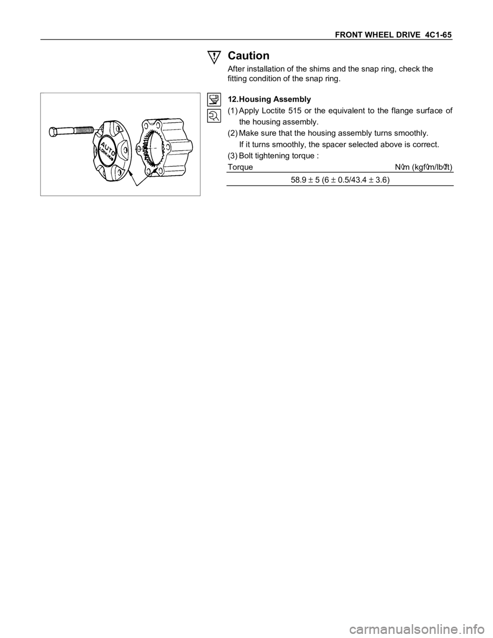
12.Housing Assembly
(1) Apply Loctite 515 or the equivalent to the flange surface of
the housing assembly.
(2) Make sure that the housing assembly turns smoothly.
If it turns smoothly, the spacer selected above is correct.
(3) Bolt tightening torque :
Torque N
m (kgfm/lbft)
58.9
5 (6 0.5/43.4 3.6)
Page 136 of 1600
FRONT WHEEL DRIVE 4C1-73
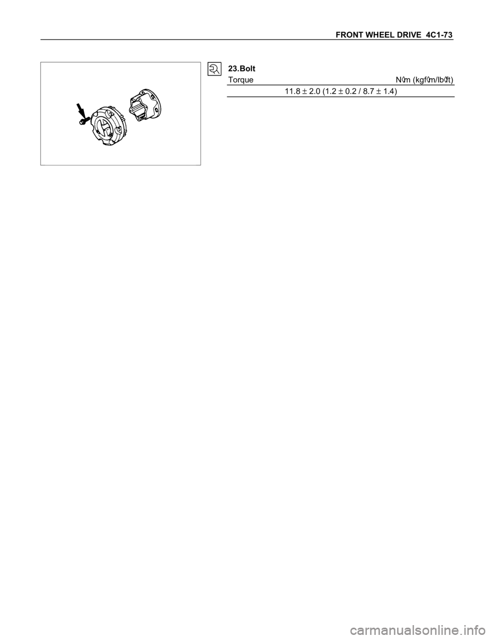
23.Bolt
Torque N
m (kgfm/lbft)
11.8
2.0 (1.2 0.2 / 8.7 1.4)
Page 138 of 1600

FRONT WHEEL DRIVE 4C1-75
2. Bolt ; Transfer Side
Torque N
m (kgfm/lbft)
Bolt size M10 62.8 3.9 (6.4 0.4/46.3 2.9)
1. Bolt ; Differential Side
Torque N
m (kgfm/lbft)
Bolt size M8 35.3 2.9 (3.6 0.3 / 26 2.2)
Page 346 of 1600
5-18 BRAKES
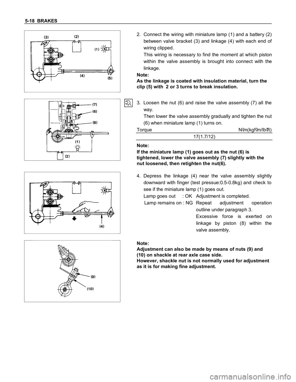
2. Connect the wiring with miniature lamp (1) and a battery (2)
between valve bracket (3) and linkage (4) with each end of
wiring clipped.
This wiring is necessary to find the moment at which piston
within the valve assembly is brought into connect with the
linkage.
Note:
As the linkage is coated with insulation material, turn the
clip (5) with 2 or 3 turns to break insulation.
3. Loosen the nut (6) and raise the valve assembly (7) all the
way.
Then lower the valve assembly gradually and tighten the nut
(6) when miniature lamp (1) turns on.
Torque N
m(kgfm/lbft)
17(1.7/12)
Note:
If the miniature lamp (1) goes out as the nut (6) is
tightened, lower the valve assembly (7) slightly with the
nut loosened, then retighten the nut(6).
4. Depress the linkage (4) near the valve assembly slightly
downward with finger (test pressue:0.5-0.8kg) and check to
see if the miniature lamp (1) goes out.
Lamp goes out : OK Adjustment is completed.
Lamp remains on : NG Repeat adjustment operation
outline under paragraph 3.
Excessive force is exerted on
linkage by piston (8) within the
valve assembly.
Note:
Adjustment can also be made by means of nuts (9) and
(10) on shackle at rear axle case side.
However, shackle nut is not normally used for adjustment
as it is for making fine adjustment.
Page 353 of 1600
BRAKES 5-25
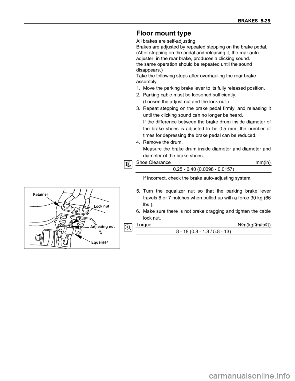
Floor mount type
All brakes are self-adjusting.
Brakes are adjusted by repeated stepping on the brake pedal.
(After stepping on the pedal and releasing it, the rear auto-
adjuster, in the rear brake, produces a clicking sound.
the same operation should be repeated until the sound
disappears.)
Take the following steps after overhauling the rear brake
assembly.
1. Move the parking brake lever to its fully released position.
2. Parking cable must be loosened sufficiently.
(Loosen the adjust nut and the lock nut.)
3. Repeat stepping on the brake pedal firmly, and releasing it
until the clicking sound can no longer be heard.
If the difference between the brake drum inside diameter of
the brake shoes is adjusted to be 0.5 mm, the number of
times for depressing the brake pedal can be reduced.
4. Remove the drum.
Measure the brake drum inside diameter and diameter and
diameter of the brake shoes.
Shoe Clearance mm(in)
0.25 - 0.40 (0.0098 - 0.0157)
If incorrect, check the brake auto-adjusting system.
5. Turn the equalizer nut so that the parking brake lever
travels 6 or 7 notches when pulled up with a force 30 kg (66
lbs.).
6. Make sure there is not brake dragging and tighten the cable
lock nut.
Torque N
m(kgfm/lbft)
8 - 18 (0.8 - 1.8 / 5.8 - 13)
Page 355 of 1600

BRAKES 5-27
Lock Nut Torque Nm(kgfm/lbft)
15- 25 (1.5 - 2.5 / 11 - 18)
d) Install the stop lamp switch.
Note:
Pedal height (L
2) must be 95 mm (3.7 in.) or more when
applying about 50 kg (110.25 lbs.) of stepping force.
Clearance
Between the Switch Housing and the Brake Pedal (A).
mm(in)
0.5 - 1.0 (0.02 - 0.04)
Page 358 of 1600

5-30 BRAKES
Important Operations - Installation
7. Front Hub and Disc Assembly
For the installation procedure, refer to the front hub and disc
reassembly procedure in Section 4C "FRONT WHEEL DRIVE".
6. Support Bracket
Torque N
m(kgfm/lbft)
139 - 171 (14.2 - 17.4 / 103 - 126)
Set up the clip and pad before installation of the support racket.
4. Clip ; Pad
Install new parts if necessary.
2. Lock Bolt
Torque N
m(kgfm/lbft)
27 - 37 (2.8 - 3.8 / 20 - 27)
1. Brake Flexible Hose
Attach the bolt and new gasket
Torque N
m(kgfm/lbft)
29 -39 (3.0 - 4.0 / 22 - 29)
After installation, bleeding and replenishing procedure must be
performed.
Wipe the circumference of the hose clean.
Note:
Always use new gaskets.
Be sure to put the hooked edge of the flexible hose end
into the anti-rotation cavity.
Page 360 of 1600

5-32 BRAKES
Installation Steps
1. Clip ; Pad
2. Pad Assembly with Shim
After attaching the pad assembly with the shim to the support
bracket, position the wear indicator to the lower side of the pad.
3. Caliper Assembly
Lower the caliper into its original position.
Do not damage the flexible hose by twisting or pulling it.
4. Lock Bolt
Attach the lock bolt to the caliper.
Torque N
m(kgfm/lbft)
27 - 37 (2.8 - 3.8 / 20 - 27)
Page 366 of 1600

5-38 BRAKES
3. Piston
When inserting the piston into the cylinder, use finger pressure
only.
Do not use a mallet or other impact tools, since damage to the
cylinder wall or ring seal can result.
4. Dust Seal ; Piston
5. Dust Seal Ring
Apply special grease (Approx. 1g) to the piston and attach the
dust seal to the piston and caliper.
Insert the dust seal ring into the dust seal.
6. Dust Boot ; Sleeve
7. Dust Boot ; Guide Pin
Install the sleeve dust boot on the caliper after applying special
grease (Approx. 1g) into the sleeve and guide pin boot, then
insert the sleeve into the dust boot.
9. Bleeder with Cap
Torque N
m(kgfm/Ibft)
5.9-8.8 (0.6 - 0.9 / 4.3 - 6.5)