torque ISUZU TFS SERIES 1997 Repair Manual
[x] Cancel search | Manufacturer: ISUZU, Model Year: 1997, Model line: TFS SERIES, Model: ISUZU TFS SERIES 1997Pages: 1600, PDF Size: 40.98 MB
Page 535 of 1600

10-38 CAB
REMOVAL AND INSTALLATION
BUCKET SEAT BENCH SEAT
Removal Steps
1. Adjust cover
2. Bolt
3. Seat assembly
4. Adjuster
Installation Steps
4. Adjuster
3. Seat assembly
2. Bolt
1. Adjust cover
Important Operation - Installation
2. Bolt
Torque N
m(kgfm/lbft)
39.2
9.8 (4 1 / 28.9 7.2)
Page 536 of 1600

CAB 10-39
FRONT AND REAR SEAT BELT
REMOVAL AND INSTALLATION
1
Removal Steps
1. Trim
2. Seat belt and retractor
Installation Steps
2. Seat belt and retractor
1. Trim
Important Operation - Installation
2. Seat Belt and Retractor
Bolt Torque N
m(kgfm/lbft)
39.2
9.8 (4 1 / 28.9 7.2)
Page 537 of 1600

10-40 CAB
JUMP SEAT
REMOVAL AND INSTALLATION
Removal Steps
1. Head rest and back trim cover
2. Hinge cover, center
3. Bolt
4. Jump seat assembly
Installation Steps
4. Jump seat assembly
3. Bolt
2. Hinge cover ; center
1. Head rest and back trim cover
Important Operation - Installation
3. Bolt
Torque N
m(kgfm/lbft)
19.6
5 (2 0.5 / 14.5 3.6)
Page 538 of 1600

CAB 10-41
JUMP SEAT BELT
REMOVAL AND INSTALLATION
Removal Steps
1. Hinge cover
2. Hinge cover ; center
3. Bolt
Installation Steps
3. Bolt
2. Hinge cover ; center
1. Hinge cover
Important Operation - Installation
3. Bolt
Torque N
m(kgfm/lbft)
39.2
9.8 (4 1 / 28.9 7.2)
Page 541 of 1600

CLUTCH 7C-1
SECTION 7C
CLUTCH
TABLE OF CONTENTS
PAGE
Main Data and Specifications ...................................<0011001100110011001100110011001100110011001100110011001100110011001100110011001100110011001100110011001100110011001100110011001100110011001100110011001100110011001100110011001100110011001100110011001100
11001100110011[ 7C- 2
General Description......................................................................................................... 7C-3
Torque Specification ...........................................<0011001100110011001100110011001100110011001100110011001100110011001100110011001100110011001100110011001100110011001100110011001100110011001100110011001100110011001100110011001100110011001100110011001100
11001100110011001100110011001100110011[ 7C-8
Servicing<0011001100110011001100110011001100110011001100110011001100110011001100110011001100110011001100110011001100110011001100110011001100110011001100110011001100110011001100110011001100110011001100110011001100
11001100110011[<0011001100110011001100110011001100110011001100110011001100110011001100110011001100110011001100110011001100110011001100110011001100110011001100110011001100110011001100110011001100110011001100110011001100
11001100110011001100110011001100110011001100110011[...... 7C- 13
Clut<0046004b0011001100110011001100110011001100110011001100110011001100110011001100110011001100110011001100110011001100110011001100110011001100110011001100110011001100110011001100110011001100110011001100110011001100
11001100110011001100110011[<0011001100110011001100110011001100110011001100110011001100110011001100110011001100110011001100110011001100110011001100110011001100110011001100110011001100110011001100110011001100110011001100110011001100
11001100110011001100110011001100110011001100110011[........ 7C- 15
Removal and Installation .......................................<0011001100110011001100110011001100110011001100110011001100110011001100110011001100110011001100110011001100110011001100110011001100110011001100110011001100110011001100110011001100110011001100110011001100
1100110011[ 7C- 15
Inspection and Repair................................................................................................. 7C- 20
Clutch Control .................................................................................................................. 7C- 27
Removal and Installation .......................................<0011001100110011001100110011001100110011001100110011001100110011001100110011001100110011001100110011001100110011001100110011001100110011001100110011001100110011001100110011001100110011001100110011001100
1100110011[ 7C- 27
Master Cylinder (Except 6VD1 Engine) .......................................................................... 7C- 30
Disassembly <0011001100110011001100110011001100110011001100110011001100110011001100110011001100110011001100110011001100110011001100110011001100110011001100110011001100110011001100110011001100110011001100110011001100
110011[<0011001100110011001100110011001100110011001100110011001100110011001100110011001100110011001100110011001100110011001100110011001100110011001100110011001100110011001100110011001100110011001100110011001100
11001100110011001100110011001100110011[ 7C-30
Inspection and Repair................................................................................................. 7C- 31
Reassembly <0011001100110011001100110011001100110011001100110011001100110011001100110011001100110011001100110011001100110011001100110011001100110011001100110011001100110011001100110011001100110011001100110011001100
1100110011[<0011001100110011001100110011001100110011001100110011001100110011001100110011001100110011001100110011001100110011001100110011001100110011001100110011001100110011001100110011001100110011001100110011001100
11001100110011001100110011001100110011[ 7C-32
Master Cylinder (6VD1 LHD Model) ................................................................................ 7C- 33
Disassembly and Reassembly ................................................................................... 7C- 33
Slave Cylinder (Except 6VD1 Engine) ............................................................................ 7C- 35
Disassembly <0011001100110011001100110011001100110011001100110011001100110011001100110011001100110011001100110011001100110011001100110011001100110011001100110011001100110011001100110011001100110011001100110011001100
110011[<0011001100110011001100110011001100110011001100110011001100110011001100110011001100110011001100110011001100110011001100110011001100110011001100110011001100110011001100110011001100110011001100110011001100
11001100110011001100110011001100110011[ 7C-35
Inspection and Repair................................................................................................. 7C- 36
Reassembly <0011001100110011001100110011001100110011001100110011001100110011001100110011001100110011001100110011001100110011001100110011001100110011001100110011001100110011001100110011001100110011001100110011001100
1100110011[<0011001100110011001100110011001100110011001100110011001100110011001100110011001100110011001100110011001100110011001100110011001100110011001100110011001100110011001100110011001100110011001100110011001100
11001100110011001100110011001100110011[ 7C-36
Hydraulic Damper Cylinder (Except 6VD1 Engine) ....................................................... 7C- 40
Inspection and Repair................................................................................................. 7C- 40
Troubleshooting .............................................................................................................. 7
C- 41
Special Service Tool ........................................................................................................ 7C-50
INDEX
Page 548 of 1600

7C-8 CLUTCH
TORQUE SPECIFICATION
STANDARD BOLTS
The torque values given in the following table should be applied where a particular torque is not specified.
N
m (kgfm/lbft)
Strength 4.8/4T 7T 8.8 9.8/9T
ClassRefined Non-Refined
Bolt Identifi-
cation
Bolt
Diameter
Pitch (mm)
-
M6 1.0 6 (0.6 / 52 lb.in) 7 (0.7 / 61 lb.in) 8 (0.8 / 69 lb.in) -
M8 1.25 13 (1.3 / 113 lb.in) 17 (1.7 / 12) 20 (2.0 / 14) 24 (2.4 / 17)
M10 1.25 27 (2.8 / 20) 37 (3.8 / 27) 42 (4.3 / 31) 50 (5.1 / 37)
M12 1.25 61 (6.3 / 45) 76 (7.8 / 56) 87 (8.9 / 64) 95 (9.7 / 70)
M14 1.5 96 (9.8 / 71) 116 (11.8 / 85) 133 (13.6 / 98) 142 (14.5 / 105)
M16 1.5 130 (13.3 / 96) 170 (17.3 / 125) 193 (19.7 / 143) 200 (20.4 / 148)
M18 1.5 188 (19.2 / 139) 244 (24.9 / 180) 278 (28.3 / 205) 287 (29.3 / 212)
M20 1.5 258 (26.3 / 190) 337 (34.4 / 249) 385 (39.3 / 284) 396 (40.4 / 292)
M22 1.5 332 (33.9 / 245) 453 (46.3 / 335) 517 (52.7 / 381) 530 (54.1 / 391)
M24 2.0 449 (45.8 / 331) 570 (58.2 / 421) 651 (66.3 / 480) 692 (70.6 / 511)
* M10 1.5 26 (2.7 / 20) 36 (3.7 / 27) 41 (4.2 / 30) 48 (4.9 / 35)
* M12 1.75 57 (5.8 / 42) 71 (7.2 / 52) 80 (8.2 / 59) 89 (9.1 / 66)
* M14 2.0 89 (9.1 / 66) 110 (11.2 / 81) 125 (12.7 / 92) 133 (13.6 / 98)
* M16 2.0 124 (12.7 / 92) 162 (16.5 / 119) 185 (18.9 / 137) 191 (19.5 / 141)
Flange BoltM6 1.0 7 (0.7 / 61 lb.in) 8 (0.8 / 69 lb.in) 9 (0.9 / 78 lb.in) -
M8 1.25 15 (1.5 / 11) 19 (1.9 / 14) 22 (2.2 / 16) 26 (2.7 / 20)
M10 1.25 31 (3.2 / 23) 41 (4.2 / 30) 47 (4.8 / 35) 56 (5.7 / 41)
M12 1.25 69 (7.0 / 51) 85 (8.7 / 63) 97 (9.9 / 72) 106 (10.8 / 78)
M14 1.5 104 (10.6 / 77) 126 (12.8 / 93) 144 (14.6 / 106) 154 (15.7 / 114)
M16 1.5 145 (14.8 / 127) 188 (19.2 / 139) 214 (21.8 / 158) 221 (22.5 / 163)
M18 1.5 - - - -
M20 1.5 - - - -
M22 1.5 - - - -
M24 2.0 - - - -
* M10 1.5 30 (3.1 / 22) 40 (4.1 / 30) 46 (4.7 / 34) 54 (5.5 / 40)
* M12 1.75 64 (6.5 / 47) 78 (8.0 / 58) 89 (9.1 / 66) 99 (10.1 / 73)
* M14 2.0 97 (9.9 / 72) 119 (12.1 / 88) 135 (13.8 / 99.7) 144 (14.7 / 107)
* M16 2.0 137 (14.0 / 101) 178 (18.2 / 132) 203 (20.7 / 132) 210 (21.5 / 155)
The asterisk * indicates that the bolts are used for female-threaded parts that are made of soft materials such as
casting, etc.
FLARE NUTS
Pipe diameter mm (in) Torque Nm (kgfm / lbft) Pipe diameter mm (in) Torque Nm (kgfm / lbft)
4.76 (0.187) 16 (1.6 / 12) 10.00 (0.394) 54 (5.5 / 40)
6.35 (0.250) 26 (2.7 / 20) 12.00 (0.472) 88 (9.0 / 65)
8.00 (0.315) 44 (4.5 / 33) 15.00 (0.591) 106 (10.8 / 78)
Standard Hex.
Head Bolt
Page 557 of 1600

CLUTCH 7C-17
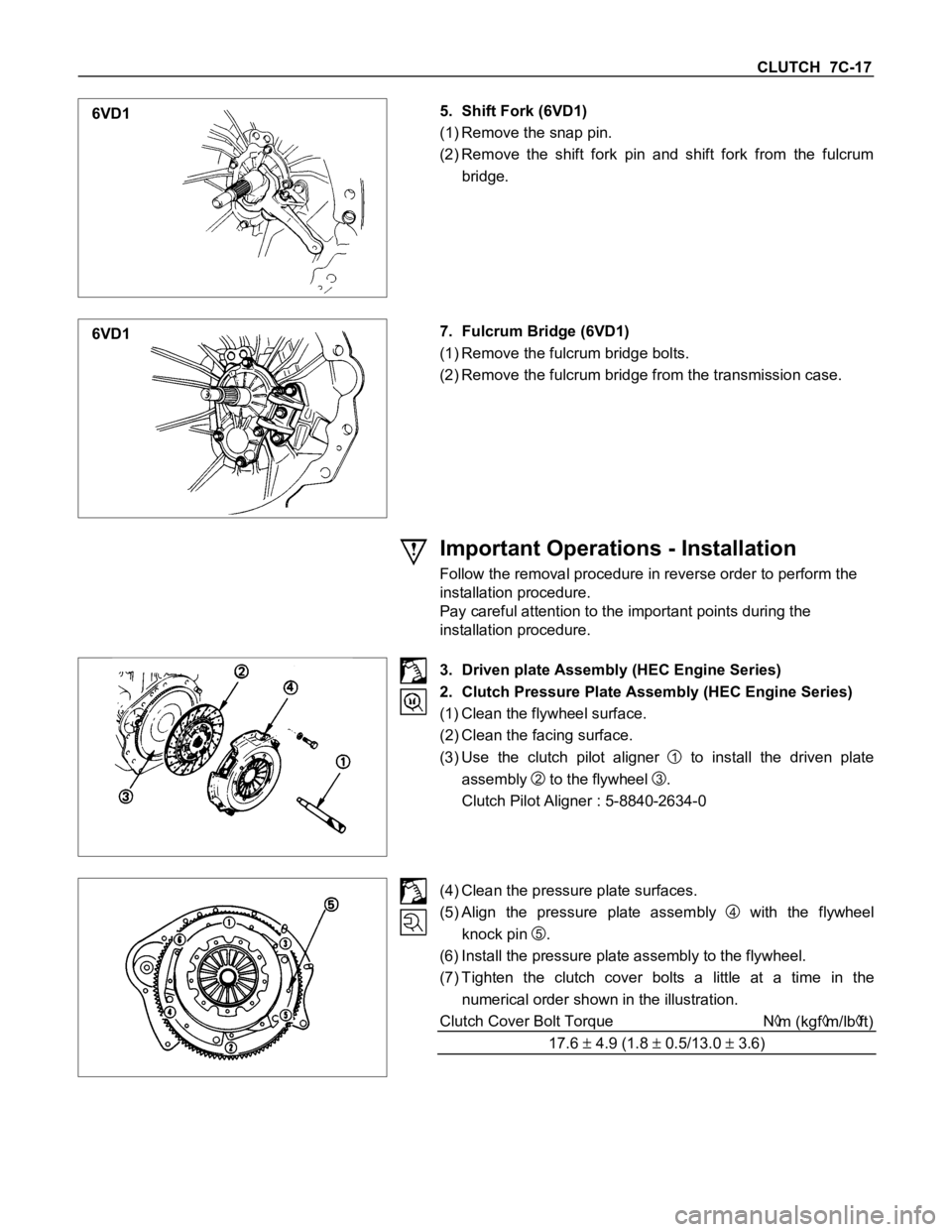
6VD15. Shift Fork (6VD1)
(1) Remove the snap pin.
(2) Remove the shift fork pin and shift fork from the fulcrum
bridge.
6VD17. Fulcrum Bridge (6VD1)
(1) Remove the fulcrum bridge bolts.
(2) Remove the fulcrum bridge from the transmission case.
Important Operations - Installation
Follow the removal procedure in reverse order to perform the
installation procedure.
Pay careful attention to the important points during the
installation procedure.
3. Driven plate Assembly (HEC Engine Series)
2. Clutch Pressure Plate Assembly (HEC Engine Series)
(1) Clean the flywheel surface.
(2) Clean the facing surface.
(3) Use the clutch pilot aligner
1 to install the driven plate
assembly
2 to the flywheel
3.
Clutch Pilot Aligner : 5-8840-2634-0
(4) Clean the pressure plate surfaces.
(5) Align the pressure plate assembly
4 with the flywheel
knock pin
5.
(6) Install the pressure plate assembly to the flywheel.
(7) Tighten the clutch cover bolts a little at a time in the
numerical order shown in the illustration.
Clutch Cover Bolt Torque N
m (kgfm/lbft)
17.6
4.9 (1.8 0.5/13.0 3.6)
Page 558 of 1600

7C-18 CLUTCH
8. Remove the clutch pilot aligner.
Note:
Do not strike the clutch pilot aligner with a hammer to
remove it.
6VD17. Fulcrum Bridge (6VD1)
(1) Install the fulcrum bridge to the transmission case.
(2) Tighten three fulcrum bridge bolts to the specified torque.
Fulcrum Bridge Bolt Torque N
m (kgm/lbft)
39 (3.9/28)
6VD15. Shift Fork (6VD1)
(1) Apply molybdenum disulfide contained type grease to the
pin hole inner circumferences and thrust surfaces.
(2) Attach the shift fork to the fulcrum bridge and insert the pin
from below of the fulcrum bridge.
(3) Install the washer and snap pin.
6VD14. Release Bearing (6VD1)
(1) Apply molybdenum disulfide contained type grease to the
areas shown in illustration.
Page 559 of 1600

CLUTCH 7C-19
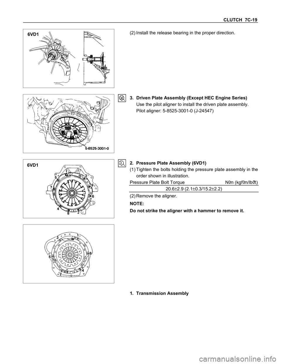
6VD1(2) Install the release bearing in the proper direction.
3. Driven Plate Assembly (Except HEC Engine Series)
Use the pilot aligner to install the driven plate assembly.
Pilot aligner: 5-8525-3001-0 (J-24547)
6VD12. Pressure Plate Assembly (6VD1)
(1) Tighten the bolts holding the pressure plate assembly in the
order shown in illustration.
Pressure Plate Bolt Torque N
m (kgfm/lbft)
20.6
2.9 (2.10.3/15.22.2)
(2) Remove the aligner.
NOTE:
Do not strike the aligner with a hammer to remove it.
1. Transmission Assembly