instrument panel ISUZU TFS SERIES 1997 Workshop Manual
[x] Cancel search | Manufacturer: ISUZU, Model Year: 1997, Model line: TFS SERIES, Model: ISUZU TFS SERIES 1997Pages: 1600, PDF Size: 40.98 MB
Page 455 of 1600

CAB 10-1
SECTION 10
CAB
TABLE OF CONTENTS
PAGE
Servicing<0011001100110011001100110011001100110011001100110011001100110011001100110011001100110011001100110011001100110011001100110011001100110011001100110011001100110011001100110011001100110011001100110011001100
11001100110011[<0011001100110011001100110011001100110011001100110011001100110011001100110011001100110011001100110011001100110011001100110011001100110011001100110011001100110011001100110011001100110011001100110011001100
11001100110011001100110011001100110011001100110011[........ 10- 2
Windshield and Back Light Glasses ................................................................................ 10- 3
Sliding Rear Window Assembly ....................................................................................... 10- 8
Doors .................................................................................................................................. 10- 12
Instrument Panel...............................................<0011001100110011001100110011001100110011001100110011001100110011001100110011001100110011001100110011001100110011001100110011001100110011001100110011001100110011001100110011001100110011001100110011001100
11001100110011001100110011001100110011001100110011[.. 10- 26
Console Box ....................................................................................................................... 10- 31
Head Lining ........................................................................................................................ 10- 33
Quarter Glass (Space Cab) ............................................................................................... 10- 36
Front Seat ........................................................................................................................... 10- 37
Front and Rear Seat Belt ................................................................................................... 10-39
<002d005800500053000300360048004400570011001100110011001100110011001100110011001100110011001100110011001100110011001100110011001100110011001100110011001100110011001100110011001100110011001100110011001100
11001100110011001100110011001100110011001100110011[<0011001100110011001100110011001100110011001100110011001100110011001100110011001100110011001100110011001100110011001100110011001100110011001100110011001100110011001100110011001100110011001100110011001100
11001100110011001100110011001100110011001100110011[...... 10- 40
Jump Seat Belt .................................................<0011001100110011001100110011001100110011001100110011001100110011001100110011001100110011001100110011001100110011001100110011001100110011001100110011001100110011001100110011001100110011001100110011001100
11001100110011001100110011001100110011001100110011[... 10- 41
INDEX
Page 480 of 1600

10-26 CAB
INSTRUMENT PANEL
REMOVAL
2 9
6
715 1013 81211
4
3
Disassembly Steps
1. Center console assembly
2. ECM cover (M/T Remote only)
3. Glove box
4. Glove box cover
5. Instrument panel passenger lower cover
assembly
6. Instrument panel driver lower cover
assembly
7. Lower cluster assembly
8. Meter cluster assembly
9. Instrument panel lower center cover
assembly
10. Control lever assembly
11. Instrument panel assembly
12. Meter assembly
13. Radio assembly
Page 481 of 1600

CAB 10-27
Important Operations
1. Center Console Assembly
Remove shift knob and 2 fixing screws (front side).
Open the grommet and remove 2 fixing screws (rear
side).
2. ECM cover
3. Glove Box
Remove 2 fixing screws and pulling the handle.
4. Glove Box Cover
Remove 4 fixing screws and pull the cover toward you
and remove the clips at 2 positions.
5. Instrument Panel Passenger Lower Cover Assembly
Remove 3 fixing screws and 1 clip.
6. Instrument Panel Driver Lower Cover Assembly
Remove the engine hood opener 2 fixing screws and 6
fixing screws.
Disconnect the connector of the illumination.
7. Lower Cluster Assembly
Remove 3 fixing clips.
8. Meter Cluster Assembly
Remove 3 fixing screws, 7 clips and switch connectors.
9. Instrument Panel Lower Center Cover Assembly
Remove 7 fixing screws and disconnect the connector of
the cigarette lighter.
Page 482 of 1600

10-28 CAB
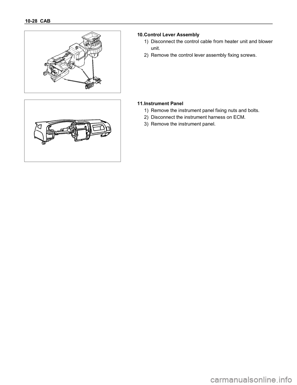
10.Control Lever Assembly
1) Disconnect the control cable from heater unit and blower
unit.
2) Remove the control lever assembly fixing screws.
11.Instrument Panel
1) Remove the instrument panel fixing nuts and bolts.
2) Disconnect the instrument harness on ECM.
3) Remove the instrument panel.
Page 483 of 1600

CAB 10-29
INSTALLATION
12
Installation Steps
1. Radio assembly
2. Meter assembly
3. Instrument panel assembly
4. Control lever assembly
5. Instrument panel lower center cover
assembly
6. Meter cluster assembly7. Lower cluster assembly
8. Instrument panel driver lower cover
assembly
9. Instrument panel passenger lower cover
assembly
10. Glove box cover
11. Glove box
12. ECM cover (M/T Remote only)
13. Center console assembly
Page 498 of 1600

CAB 10-1
SECTION 10
CAB
TABLE OF CONTENTS
PAGE
Servicing<0011001100110011001100110011001100110011001100110011001100110011001100110011001100110011001100110011001100110011001100110011001100110011001100110011001100110011001100110011001100110011001100110011001100
11001100110011[<0011001100110011001100110011001100110011001100110011001100110011001100110011001100110011001100110011001100110011001100110011001100110011001100110011001100110011001100110011001100110011001100110011001100
11001100110011001100110011001100110011001100110011[........ 10- 2
Windshield and Back Light Glasses ................................................................................ 10- 3
Sliding Rear Window Assembly ....................................................................................... 10- 8
Doors .................................................................................................................................. 10- 12
Instrument Panel...............................................<0011001100110011001100110011001100110011001100110011001100110011001100110011001100110011001100110011001100110011001100110011001100110011001100110011001100110011001100110011001100110011001100110011001100
11001100110011001100110011001100110011001100110011[.. 10- 26
Console Box ....................................................................................................................... 10- 31
Head Lining ........................................................................................................................ 10- 33
Quarter Glass (Space Cab) ............................................................................................... 10- 36
Front Seat ........................................................................................................................... 10- 37
Front and Rear Seat Belt ................................................................................................... 10-39
<002d005800500053000300360048004400570011001100110011001100110011001100110011001100110011001100110011001100110011001100110011001100110011001100110011001100110011001100110011001100110011001100110011001100
11001100110011001100110011001100110011001100110011[<0011001100110011001100110011001100110011001100110011001100110011001100110011001100110011001100110011001100110011001100110011001100110011001100110011001100110011001100110011001100110011001100110011001100
11001100110011001100110011001100110011001100110011[...... 10- 40
Jump Seat Belt .................................................<0011001100110011001100110011001100110011001100110011001100110011001100110011001100110011001100110011001100110011001100110011001100110011001100110011001100110011001100110011001100110011001100110011001100
11001100110011001100110011001100110011001100110011[... 10- 41
INDEX
Page 523 of 1600

10-26 CAB
INSTRUMENT PANEL
REMOVAL
2 9
6
715 1013 81211
4
3
Disassembly Steps
1. Center console assembly
2. ECM cover (M/T Remote only)
3. Glove box
4. Glove box cover
5. Instrument panel passenger lower cover
assembly
6. Instrument panel driver lower cover
assembly
7. Lower cluster assembly
8. Meter cluster assembly
9. Instrument panel lower center cover
assembly
10. Control lever assembly
11. Instrument panel assembly
12. Meter assembly
13. Radio assembly
Page 524 of 1600

CAB 10-27
Important Operations
1. Center Console Assembly
Remove shift knob and 2 fixing screws (front side).
Open the grommet and remove 2 fixing screws (rear
side).
2. ECM cover
3. Glove Box
Remove 2 fixing screws and pulling the handle.
4. Glove Box Cover
Remove 4 fixing screws and pull the cover toward you
and remove the clips at 2 positions.
5. Instrument Panel Passenger Lower Cover Assembly
Remove 3 fixing screws and 1 clip.
6. Instrument Panel Driver Lower Cover Assembly
Remove the engine hood opener 2 fixing screws and 6
fixing screws.
Disconnect the connector of the illumination.
7. Lower Cluster Assembly
Remove 3 fixing clips.
8. Meter Cluster Assembly
Remove 3 fixing screws, 7 clips and switch connectors.
9. Instrument Panel Lower Center Cover Assembly
Remove 7 fixing screws and disconnect the connector of
the cigarette lighter.
Page 525 of 1600

10-28 CAB
10.Control Lever Assembly
1) Disconnect the control cable from heater unit and blower
unit.
2) Remove the control lever assembly fixing screws.
11.Instrument Panel
1) Remove the instrument panel fixing nuts and bolts.
2) Disconnect the instrument harness on ECM.
3) Remove the instrument panel.
Page 526 of 1600

CAB 10-29
INSTALLATION
12
Installation Steps
1. Radio assembly
2. Meter assembly
3. Instrument panel assembly
4. Control lever assembly
5. Instrument panel lower center cover
assembly
6. Meter cluster assembly7. Lower cluster assembly
8. Instrument panel driver lower cover
assembly
9. Instrument panel passenger lower cover
assembly
10. Glove box cover
11. Glove box
12. ECM cover (M/T Remote only)
13. Center console assembly