battery location ISUZU TROOPER 1995 Workshop Manual
[x] Cancel search | Manufacturer: ISUZU, Model Year: 1995, Model line: TROOPER, Model: ISUZU TROOPER 1995Pages: 1928
Page 211 of 1928
SUPPLEMENTAL RESTRAINT SYSTEM (SRSl STEERING WHEEL & COLUMN 3F4-1
SECTION 3F4
SUPPLEMENTAL RESTRAINT SYSTEM
STEERING
WHEEL & COLUMN
W CAUTION:
When fasteners are removed, always reinstall them at the same location from which they were removed.
If a fastener needs to be replaced, use the correct part number fastener for that application. If the correct
part
number fastener is not available, a fastener of equal size and strength (or stronger) may be used.
Fasteners
that are not reused, and those requiring thread locking compound, will be called out. The correct
torque value must be used when installing fasteners that require it. If the above conditions are not
followed, parts or system damage could result.
CONTENTS
General Description .......................................... 3F4-1
Lock Cylinder Replacement ......................... 3F4-10
On-Vehicle Service
............................................ 3F4-2 Steering Column Replacement .................... 3F4-13
Special Service Precaution ........................... 3F4-2 Main Data and Specifications .......................... 3F4-17
Inflator Module Replacement ...................... 3F4-3 Torque
Specifications ................................... 3F4-17
Steering Wheel Replacement ...................... 3F4-4 Special Tools ..................................................... 3F4-17
Combination
Switch Replacement ............. 3F4-7
GENERAL DESCRIPTION
W WARNING
TO AVOID DEPLOYMENT WHEN TROUBLE
SHOOTING
THE SRS SYSTEM, DO NOT USE
ELECTRICAL TEST EQUIPMENT, SUCH AS
BATTERY-POWERED OR A/C-POWERED VOLT
METER, OHMMETER, ETC., OR ANY TYPE OF
ELECTRICAL EQUIPMENT OTHER THAN SPE
CIFIED IN THIS MANUAL. DO NOT USE A NON
POWERED
PROBE-TYPE TESTER.
INSTRUCTION IN THIS MANUAL MUST BE
FOLLOWED CAREFULLY, OTHERWISE PER
SONAL INJURY MAY RESULT.
This steering
wheel and column repair section covers
the Supplemental Restraint System (SRS) steering
column. The following repair procedures are specific
to SRS Components. When servicing a vehicle
equipped with Supplemental Restraint System, pay
close attention to all WARNINGS and CAUTIONS.
For detailed explanation about SRS, refer to Section
9J "SUPPLEMENTAL
RESTRAINT SYSTEM (SRS)" of
this manual.
The steering column has three important features in
addition to the steering function:
1. The column is energy absorbing, designed to
compress in a front-end collision to minimize the
possibility of injury to the driver of the vehicle.
2. The ignition switch and lock are mounted con
veniently on the column.
3. With the column mounted lock, the ignition and
steering operation can be
locked to prevent theft
of the vehicle.
The column may be disassembled and reassembled.
To insure the energy absorbing action, it is important
that the specified screws, bolts and nuts be used only
as designated and that they are tightened to the
specified torque.
When the column is removed from the vehicle, a
sharp
blow on the end of steering shaft or shift lever,
leaning
on the column assembly, or dropping the
assembly could shear or loosen the fasteners that
maintain column rigidity.
Page 500 of 1928
6-2 ENGINE DIAGNOSIS
SECTION 6E-DRIVEABILITY
AND EMISSIONS
This section covers emission control systems general
information, and diagnostic procedures which will lead
to repairing performance and driveability related
problems.
Emission components are covered, as well
as removal and replacement procedures.
Instructions on use
of special tools are also given.
SECTION 6F-ENGINE EXHAUST
This section has information on all exhaust system
parts, such
as tailpipes, mufflers, and the catalytic
converter.
GENERAL DESCRIPTION
ENGINE CLEANLINESS AND CARE
An automobile engine is a combination of many
machined, honed,
polished and lapped surfaces with
tolerances that are measured in the thousandths of a
millimeter (ten thousandths of an inch). Accordingly,
when any
internal engine parts are serviced, care and
cleanliness are important. Throughout this section, it
should be understood that proper cleaning and
protection
of machined surfaces and friction areas is
part
of the repair procedure. This is considered
standard shop practice even
if not specifically stated.
• A liberal coating of engine oil should be applied to
all friction areas during assembly to protect and
lubricate the surfaces on initial operation.
• Whenever valve train components, pistons, piston
rings, connecting rods, rod bearings, and
crankshaft
journal bearings are removed for
service, they should be retained in order.
• At the time of installation, they should be installed
in the same locations and with the same mating
surfaces
as when removed.
• Battery cables should be disconnected before any
major
work is performed on the engine. Failure to
disconnect
cables may result in damage to wire
harness
or other electrical parts.
• The six cylinders of this engine are identified by
numbers; Right side
cylinders 1, 3 and 5, Left side
cylinders 2, 4 and 6, as counted from crankshaft
pulley side to flywheel side.
GENERAL INFORMATION ON ENGINE
SERVICE
The following information on engine service should be
noted
carefully, as it is important in preventing damage
and contributing
to reliable engine performance.
• When raising or supporting the engine for any
reason,
do not use a jack under the oil pan. Due to
the
small clearance between the oil pan and the oil
pump strainer, jacking against the oil pan may
cause damage to the
oil pick-up unit.
• The 12-volt electrical system is capable of
damaging circuits. When performing any work
where electrical terminals could possibly be
grounded, the ground cable of the battery should
be disconnected at the battery.
• Any time the intake air duct or air cleaner is
removed, the intake opening
should be covered.
This
will protect against accidental entrance of
foreign material into the cylinder which could
cause extensive damage when the engine is
started.
ENGINE DIAGNOSIS
CONTENTS
Hard Starting . . . . . . . . . . . . . . . . . . . . . . . . . 6-3
Engine Compression
Test Procedure ..... 6-4
Rough Engine
Idling or Engine Stalling . . . 6-5
Rough Engine Running . . . . . . . . . . . . . . . . .
6-6
Hesitation . . . . . . . . . . . . . . . . . . . . . . . . . . . . 6-7
Engine Lacks
Power . . . . . . . . . . . . . . . . . . . . 6-8
Engine
Noisy .......................... 6-10
Abnormal Combustion . . . . . . . . . . . . . . . . . . 6-12
Engine Oil Consumption Excessive . . . . . . . 6-13
Fuel Consumption Excessive ............. 6-14
Oil Problems . . . . . . . . . . . . . . . . . . . . . . . . . . 6-14
Malfunction Indicator Lamp . . . . . . . . . . . . . . 6-15
Engine Oil Pressure Check ............... 6-16
Inspection of Hydraulic Lash Adjuster . . . . . 6-17
Page 734 of 1928
6E2-38 DRIVEABILITV AND EMISSIONS
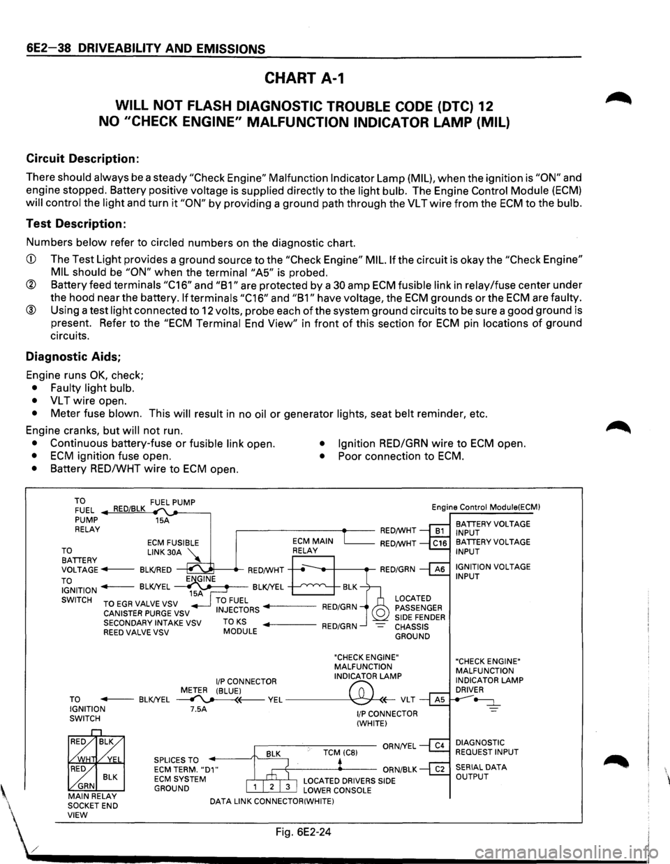
CHART A-1
WILL NOT FLASH DIAGNOSTIC TROUBLE CODE (DTC) 12
NO "CHECK ENGINE" MALFUNCTION INDICATOR LAMP (MIL)
Circuit Description:
There should always be a steady "Check Engine" Malfunction Indicator Lamp (MIL), when the ignition is "ON" and
engine stopped. Battery positive
voltage is supplied directly to the light bulb. The Engine Control Module (ECM)
will control the light and turn it "ON" by providing a ground path through the VL T wire from the ECM to the bulb.
Test Description:
Numbers below refer to circled numbers on the diagnostic chart.
CD The Test Light provides a ground source to the "Check Engine" MIL. If the circuit is okay the "Check Engine"
MIL should
be "ON" when the terminai"A5" is probed.
® Battery feed terminals "C16" and "B1" are protected by a 30 amp ECM fusible link in relay/fuse center under
the hood near the battery.
If terminals "C16" and "B1" have voltage, the ECM grounds or the ECM are faulty.
® Using a test light connected to 12 volts, probe each of the system ground circuits to be sure a good ground is
present. Refer to the
"ECM Terminal End View" in front of this section for ECM pin locations of ground
circuits.
Diagnostic Aids;
Engine runs OK, check;
• Faulty light bulb.
•
VL T wire open.
• Meter fuse blown. This will result in no oil or generator lights, seat belt reminder, etc.
Engine cranks, but
will not run.
• Continuous battery-fuse or fusible link open. • Ignition RED/GRN wire to ECM open.
• ECM ignition fuse open. • Poor connection to ECM.
• Battery RED/WHT wire to ECM open.
TO FUEL .._..,==~ ,__,__-----, PUMP 15A
RELAY .--------~~-RED/WHT Engine
Control
Module(ECM)
BATIERY VOLTAGE
INPUT
ECM FUSIBLE RED/WHT TO LINK 30A '\.. BATIERY ~ VOLTAGE---BLK!RED ~---.-RED/WHT
TO IGNITION - BLK!YEL ~~~-BLK!YEL --'--'~"'---..__
SWITCH TO EGR VALVE VSV
CANISTER PURGE VSV
SECONDARY INTAKE VSV
REED VALVE VSV TO KS MODULE
LOCATED
PASSENGER
SIDE FENDER CHASSIS GROUND
"CHECK ENGINE"
MALFUNCTION
I/P CONNECTOR INDICATOR LAMP
METER (BLUE)
("";:; TO - BLK!YEL ~(---VEL~(;-VLT IGNITION 7.5A SWITCH
BLK ~ GRN MAIN RELAY
SOCKETEND SPLICES
TO ECM TERM. "D1" ECM SYSTEM GROUND
DATA
LINK CONNECTOR(WHITE)
1/P CONNECTOR
(WHITE)
BA TIERY VOLTAGE INPUT
IGNITION
VOLTAGE INPUT
"CHECK ENGINE"
MALFUNCTION
INDICATOR
LAMP DRIVER
~
DIAGNOSTIC REQUEST INPUT
' VIEW Fig. 6E2-24
./ .................................... __________________________ _
Page 816 of 1928
6E2 120 DRIVEABILITY AND EMISSIONS
THROTTLE BODY (TB) ASSEMBLY
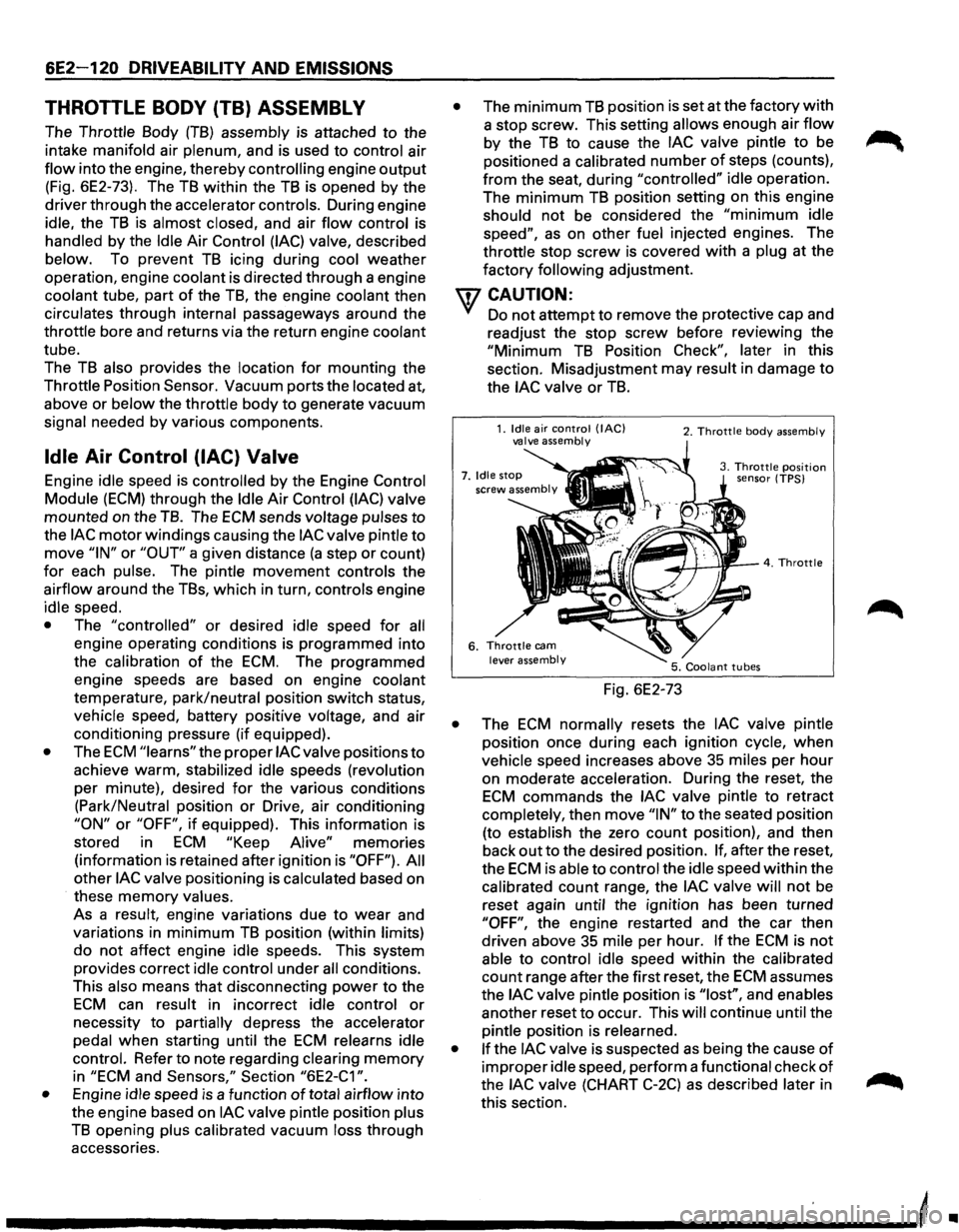
The Throttle Body (TB) assembly is attached to the
intake manifold air
plenum, and is used to control air
flow into the engine, thereby controlling engine output
(Fig. 6E2-73). The TB within the TB is opened by the
driver through the accelerator controls. During engine
idle, the
TB is almost closed, and air flow control is
handled by the Idle Air Control (lAC) valve, described
below. To prevent
TB icing during cool weather
operation, engine
coolant is directed through a engine
coolant tube, part
of the TB, the engine coolant then
circulates through internal passageways around the
throttle bore and returns via the return engine coolant
tube.
The
TB also provides the location for mounting the
Throttle Position
Sensor. Vacuum ports the located at,
above or
below the throttle body to generate vacuum
signal needed
by various components.
Idle Air Control (lAC) Valve
Engine idle speed is controlled by the Engine Control
Module (ECM) through the Idle Air Control (lAC) valve
mounted on the
TB. The ECM sends voltage pulses to
the lAC motor windings causing the lAC valve pintle to
move "IN" or "OUT" a given distance (a step or count)
for each pulse. The pintle movement controls the
airflow around the TBs, which in turn, controls engine
idle speed.
• The "controlled" or desired idle speed for all
engine operating conditions is programmed into
the
calibration of the ECM. The programmed
engine speeds are based on engine coolant
temperature, park/neutral position switch status,
vehicle speed, battery positive voltage, and air
conditioning pressure (if equipped).
• The ECM "learns" the proper lAC valve positions to
achieve warm, stabilized idle speeds (revolution
per minute), desired
for the various conditions
(Park/Neutral position
or Drive, air conditioning
"ON" or "OFF", if equipped). This information is
stored in
ECM "Keep Alive" memories
(information
is retained after ignition is "OFF"). All
other lAC valve positioning is calculated based on
these
memory values.
As a
result, engine variations due to wear and
variations in
minimum TB position (within limits)
do not affect engine idle speeds. This system
provides correct idle control under
all conditions.
This also means
that disconnecting power to the
ECM can result in incorrect idle control or
necessity to partially depress the accelerator
pedal
when starting until the ECM relearns idle
control. Refer to note regarding clearing
memory
in "ECM and Sensors," Section "6E2-C1 ".
•
Engine idle speed is a function of total airflow into
the engine based on
lAC valve pintle position plus
TB opening plus calibrated vacuum loss through
accessories.
• The minimum TB position is set at the factory with
a stop screw. This setting allows enough air flow
by the TB to cause the lAC valve pintle to be
positioned a calibrated
number of steps (counts),
from the seat, during "controlled" idle operation.
The
minimum TB position setting on this engine
should not be considered the
"minimum idle
speed", as on other fuel injected engines. The
throttle stop
screw is covered with a plug at the
factory
following adjustment.
U7 CAUTION:
VI Do not attempt to remove the protective cap and
readjust the stop screw before
reviewi~g t~e
"Minimum TB Position Check", later m th1s
section. Misadjustment may result in damage to
the lAC valve or TB.
Fig. 6E2-73
2. Throttle body assembly
3. Throttle position sensor (TPS)
• The ECM normally resets the lAC valve pintle
position once during each ignition cycle,
when
vehicle speed increases above 35 miles per hour
on moderate acceleration. During the reset, the
ECM commands the lAC valve pintle to retract
completely, then move
"IN" to the seated position
(to establish the zero
count position), and then
back
out to the desired position. If, after the reset,
the
ECM is able to control the idle speed within the
calibrated count range, the
lAC valve will not be
reset again until the ignition has been turned
"OFF", the engine restarted and the car then
driven above 35 mile per hour.
If the ECM is not
able to control idle speed within the calibrated
count range after the first reset, the
ECM assumes
the
lAC valve pintle position is "lost", and enables
another reset
to occur. This will continue until the
pintle position is relearned.
• If the lAC valve is suspected as being the cause of
improper idle speed, perform a functional check of
the lAC valve (CHART C-2C) as described later in
this section.
-----------------------------'
•
Page 1192 of 1928
-·*; ~---
8-2 CHASSIS ELECTRICAL
GENERAL INFORMATION
The chassis electrical system is of 12-volt specifications with a negative ground polarity.
Wire sizes are appropriate
to respective circuits, and classified by color. (The classification of harnesses by
color is shown on the circuit diagram for ease of harness identification.)
The
wire size is determined by load capacity and the length of wire required.
The
vehicle harnesses are: body harness, chassis harness, engine room harness, instrument harness,
transmission harness, engine
ECGI harness, dome light harness, door harness, rear body harness, tailgate
harness,
SRS harness and battery cables.
The harnesses are protected either
by tape or corrugated tube, depending on harness location.
The circuit
for each system consists of the power source, wire, fuse, relay, switch, load parts and ground, all of
which are shown on the circuit diagram.
In this manual, each electrical device is classified by system. For major parts shown on the circuit based on
the circuit diagram
for each system, a summary, diagnosis oftroubles, inspection and removal and installation
procedures are detailed.
NOTES FOR WORKING ON ELECTRICAL ITEMS
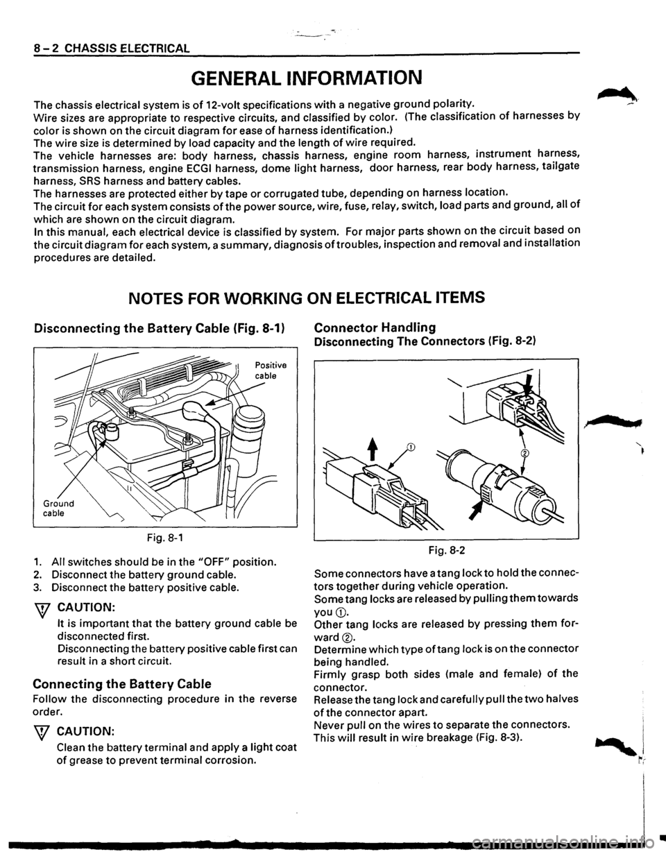
Disconnecting the Battery Cable (Fig. 8-1)
Ground cable
Fig. 8-1
1. All switches should be in the "OFF" position.
2. Disconnect the battery ground cable.
3. Disconnect the battery positive cable.
W CAUTION:
It is important that the battery ground cable be
disconnected first.
Disconnecting the battery positive cable first can
result in a short circuit.
Connecting the Battery Cable
Follow the disconnecting procedure in the reverse
order.
\V CAUTION:
Clean the battery terminal and apply a light coat
of grease to prevent terminal corrosion.
Connector Handling
Disconnecting The Connectors (Fig. 8-2)
Fig. 8-2
Some connectors have a tang lock to hold the connec
tors together during vehicle operation.
Some tang locks are released by pulling them towards
you
G).
Other tang locks are released by pressing them for
ward®.
Determine which type oftang lock is on the connector
being handled.
Firmly grasp both sides (male and female)
of the
connector. Release the tang lock and carefully pull the
two halves
of the connector apart.
Never pull on the wires
to separate the connectors.
This
will result in wire breakage (Fig. 8-3).
.,
..
Page 1202 of 1928
8-12 CHASSIS ELECTRICAL
FUSIBLE LINK
The fusible link is primarily used to protect circuits
where high amounts
of current flow and where is
would not be practical to use a fuse. For example, the
starter circuit. When a current
overload occurs, the
fusible link melts open and interrupts the flow of
current so as to prevent the rest of the wiring harness
from burning.
Determine the cause
ofthe overload before replacing
the fusible link. The replacement fusible link must
have the same amperage specification as the original
fusible link.
Never replace a blown fusible link with fusible link of
a different amperage specification. Doing so can
result in an electrical fire or other serious circuit
damage.
A
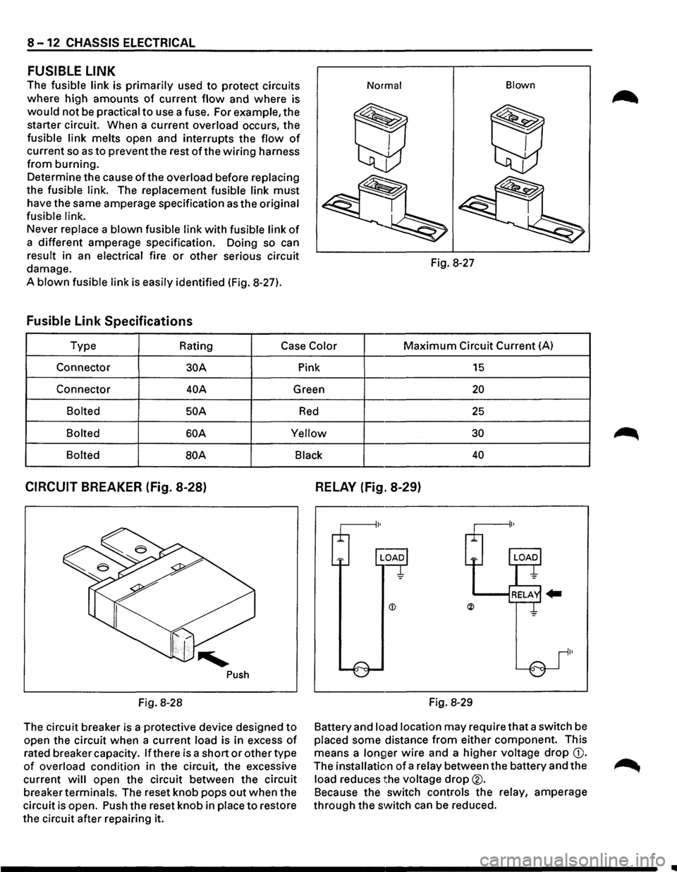
blown fusible link is easily identified (Fig. 8-27).
Fusible Link Specifications
Normal Blown
Fig.
8-27
Type Rating
Case Color Maximum Circuit Current (A)
Connector
30A Pink 15
Connector 40A Green 20
Bolted 50 A Red 25
Bolted 60A Yellow 30
Bolted
BOA Black 40
CIRCUIT BREAKER (Fig. 8-28)
Push
Fig. 8-28
The circuit breaker is a protective device designed
to
open the circuit when a current load is in excess of
rated breaker capacity. If there is a short or other type
of overload condition in the circuit, the excessive
current
will open the circuit between the circuit
breaker
terminals. The reset knob pops out when the
circuit is open. Push the reset knob in
place to restore
the circuit after repairing it.
RELAY (Fig. 8-29)
Fig. 8-29
Battery and
load location may require that a switch be
placed some distance from either component. This
means a
longer wire and a higher voltage drop G).
The installation of a relay between the battery and the
load reduces the voltage drop®.
Because the switch controls the relay, amperage
through the switch can be reduced.
..
Page 1278 of 1928
8 -88 CHASSIS ELECTRICAL
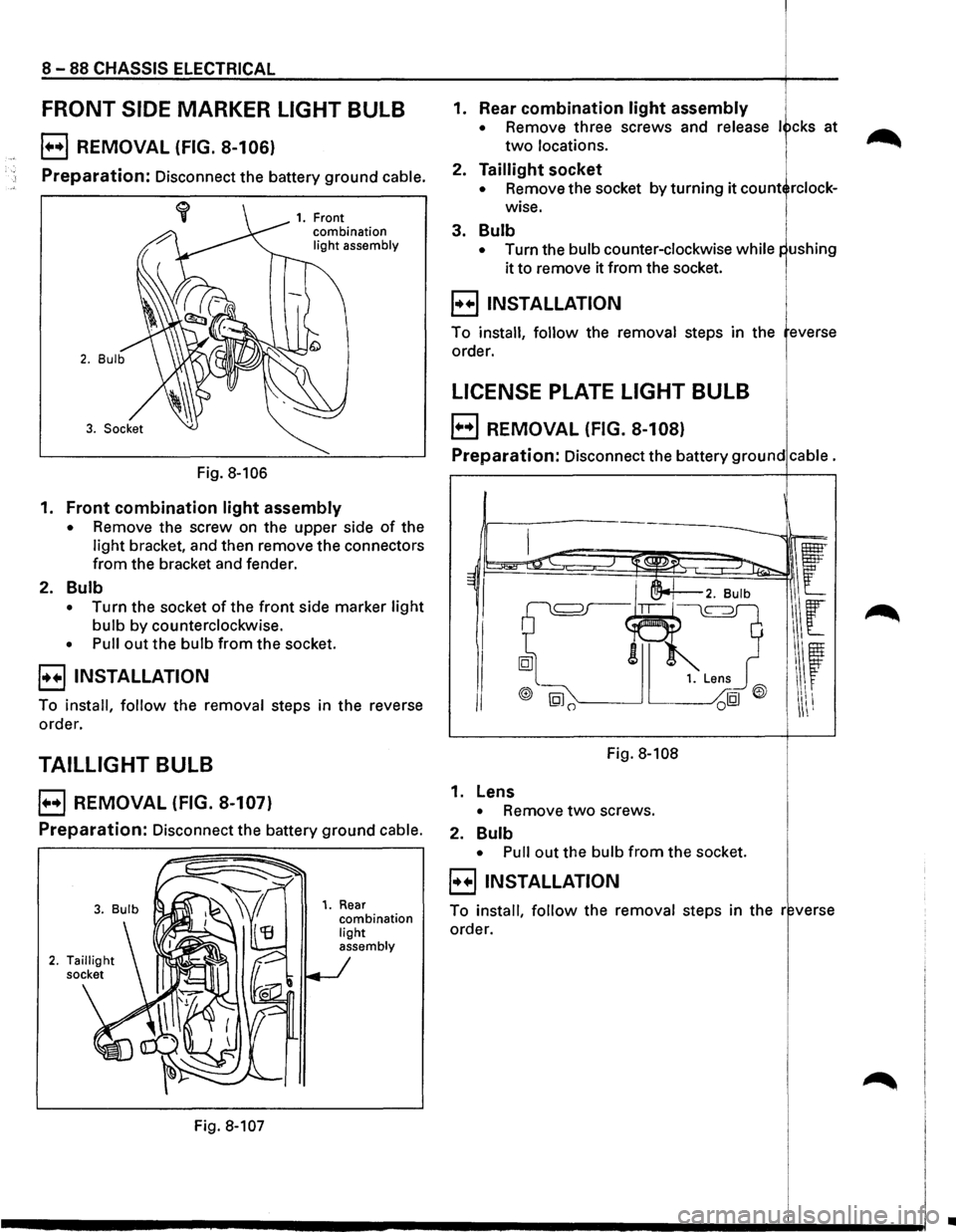
FRONT SIDE MARKER LIGHT BULB
E) REMOVAL (FIG. 8-106)
Preparation: Disconnect the battery ground cable.
Fig. 8-106
1. Front
combination
light assembly
1. Front combination light assembly
• Remove the screw on the upper side of the
light bracket, and then remove the connectors
from the bracket and fender.
2. Bulb
• Turn the socket of the front side marker light
bulb by counterclockwise.
• Pull out the bulb from the socket.
8 INSTALLATION
To install, follow the removal steps in the reverse
order.
TAILLIGHT BULB
EJ REMOVAL (FIG. 8-107)
Preparation: Disconnect the battery ground cable.
Fig. 8-107
1. Rear combination light
assembly
1. Rear combination light assembly
• Remove three screws and release I cks at
two locations.
2. Taillight socket
• Remove the socket by turning it count rclock
wise.
3. Bulb
• Turn the bulb counter-clockwise while
it to remove it from the socket.
8 INSTALLATION i
To install, follow the removal steps in the everse
order.
LICENSE PLATE LIGHT BULB 1.
E) REMOVAL (FIG. 8-108)
Preparation: Disconnect the battery ground cable.
Fig. 8-108
1. Lens
• Remove two screws.
2.
Bulb
• Pull out the bulb from the socket.
8 INSTALLATION
To install, follow the removal steps in the r verse
order.
..
Page 1325 of 1928
EJ INSTALLATION
To install, follow the removal steps in the reverse
order.
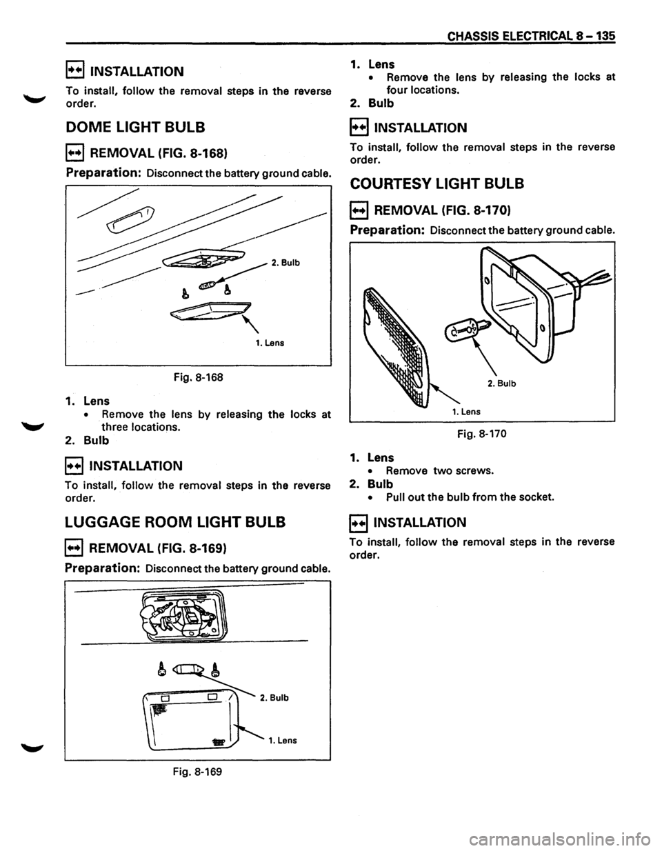
DOME LIGHT BULB
B REMOVAL (FIG. 8-168)
Preparation: Disconnect the battery ground cable.
Fig. 8-168
1. Lens
• Remove the lens by releasing the locks at
"-" three locations.
2. Bulb
B INSTALLATION
To install, follow the removal steps in the reverse
order.
LUGGAGE ROOM LIGHT BULB
B REMOVAL (FIG. 8-169)
Preparation: Disconnect the battery ground cable.
Fig. 8-169
CHASSIS ELECTRICAL 8 -135
1. Lens
• Remove the lens by releasing the locks at
four locations.
2. Bulb
B INSTALLATION
To install, follow the removal steps in the reverse
order.
COURTESY LIGHT BULB
B REMOVAL (FIG. 8-170)
Preparation: Disconnect the battery ground cable.
2. Bulb
Fig. 8-170
1. Lens
• Remove two screws.
2. Bulb
• Pull out the bulb from the socket.
E) INSTALLATION
To install, follow the removal steps in the reverse
order.
Page 1441 of 1928
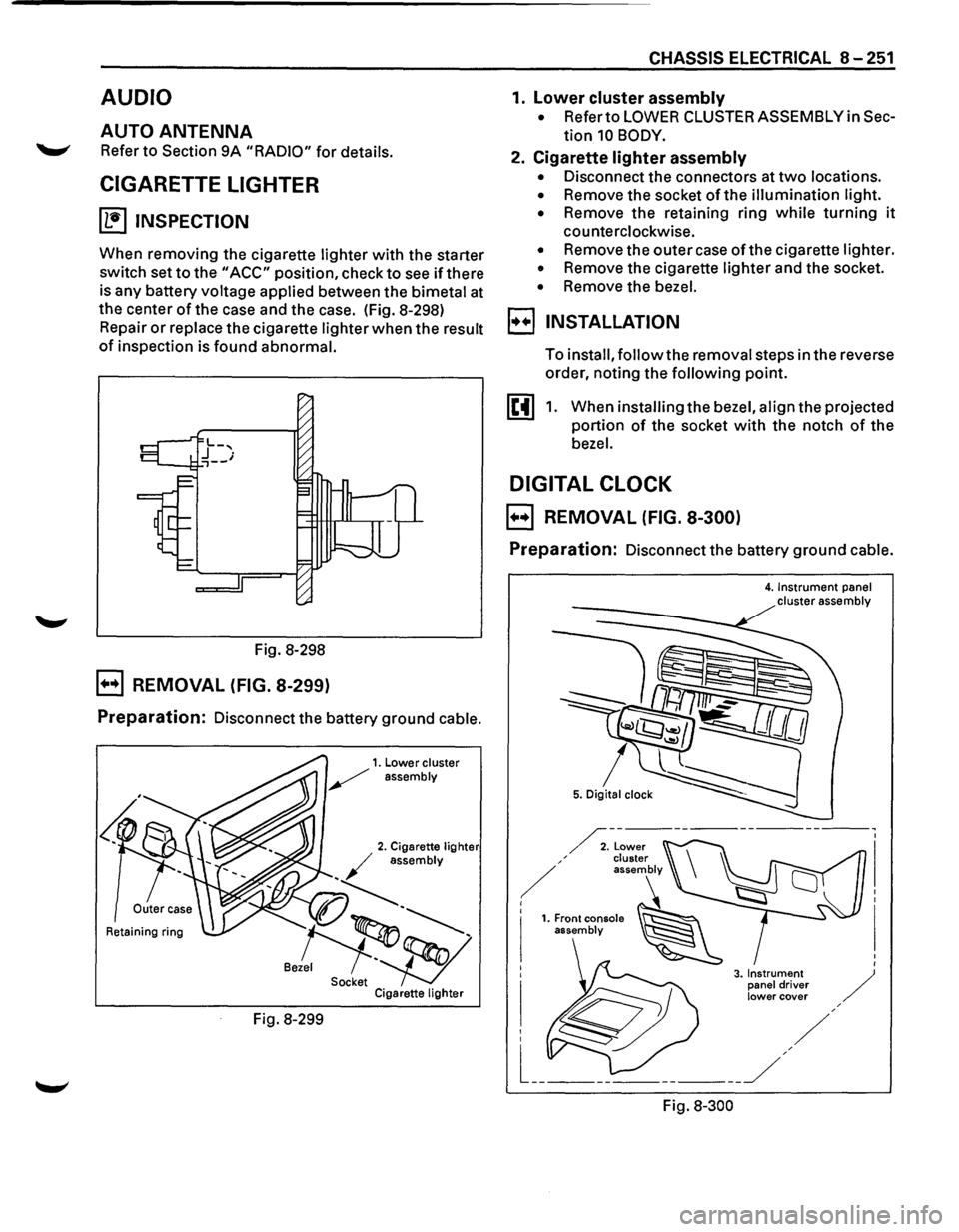
AUDIO
AUTO ANTENNA
Refer to Section 9A "RADIO" for details.
CIGARETTE LIGHTER
~ INSPECTION
When removing the cigarette lighter with the starter
switch set
to the "ACC" position, check to see if there
is any battery voltage applied between the bimetal at
the center
of the case and the case. (Fig. 8-298)
Repair
or replace the cigarette lighter when the result
of inspection is found abnormal.
Fig. 8-298
B REMOVAL (FIG. 8-299)
Preparation: Disconnect the battery ground cable.
Retaining ring
Fig. 8-299
CHASSIS ELECTRICAL 8-251
1. lower cluster assembly
• Refer to LOWER CLUSTER ASSEMBLY in Sec
tion 10 BODY.
2. Cigarette lighter assembly
• Disconnect the connectors at two locations.
• Remove the socket of the illumination light.
•
Remove the retaining ring while turning it
counterclockwise.
• Remove the outer case of the cigarette lighter.
• Remove the cigarette lighter and the socket.
• Remove the bezel.
I••! INSTALLATION
To install, follow the removal steps in the reverse
order, noting the
following point.
1. When installing the bezel, align the projected
portion
of the socket with the notch of the
bezel.
DIGITAL CLOCK
B REMOVAL (FIG. 8-300)
Preparation: Disconnect the battery ground cable.
Fig.
8-300
4. Instrument panel cluster assembly
Page 1577 of 1928
RADIO 9A-1
ACCESSORIES
Radio .................................................. .
Parts Location ..............................•...........
Circuit Diagram ......•.................................
Antenna ....•......................................•........
Auto Antenna ......................................... .
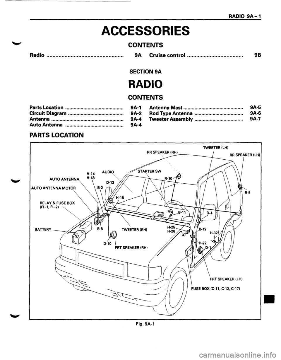
PARTS LOCATION
AUDIO
AUTO ANTENNA
AUTO ANTENNA MOTOR
CONTENTS
9A Cruise control ................................... ..
SECTION 9A
RADIO
CONTENTS
9A-1
9A-2
9A-4
9A-4 Antenna
Mast ........ ~ ................................. .
Rod Type Antenna .................................. .
Tweeter
Assembly .................................. .
lWEETER (LH)
98
9A-5
9A-6
9A·7
RR SPEAKER !RH) ----~ RR SPEAKER (lHl
BATTERY lWEETER (RH)
FRT SPEAKER (LHl
FUSE BOX (C-11, C-12, C-17)
Fig. 9A-1
•