fuel cap ISUZU TROOPER 1995 Workshop Manual
[x] Cancel search | Manufacturer: ISUZU, Model Year: 1995, Model line: TROOPER, Model: ISUZU TROOPER 1995Pages: 1928
Page 19 of 1928
(
(
(
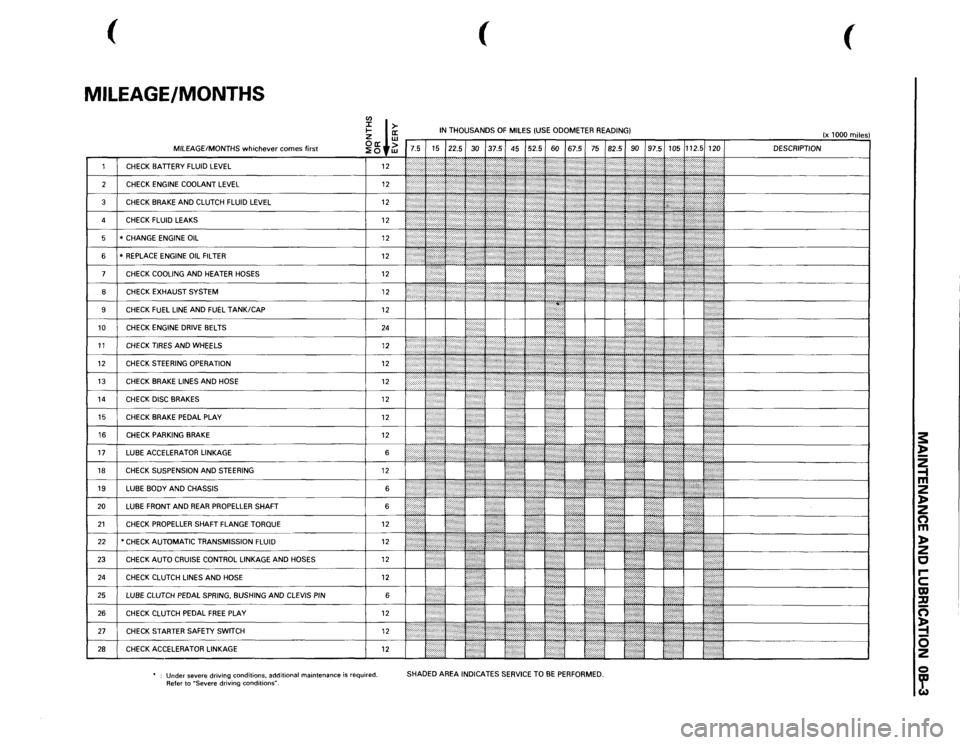
MILEAGE/MONTHS
rn
I ffi
IN THOUSANDS
OF
MILES
(USE
ODOMETER READING)
(x 1000
miles)
~ +~
7.5 15 22.5
30
37.5 45 52.5
60
67.5
75
82.5
90
97.5
105
112.5
120 DESCRIPTION
1
CHECK
BATTERY
FLUID
LEVEL
12
2'-'.:j:
:':
';;;;;
I '' ''
,,,,,,,,,:
[}
2
CHECK
ENGINE
COOLANT
LEVEL
12
':iti:·:
(''''/''?
'';?
,,,,,,,;.;.,.,....
,,,~~
3
CHECK
BRAKE
AND
CLUTCH
FLUID
LEVEL
12
:;:;:;:;:·:·:·.
\::':\' '\"':(\':'''''''''
:'·'·'·:·.,.,,,,
d~~~~~~-------------~
)''
'"''''{''''
'}';;o;o;;
l':':':·:o·.·o·····
4
CHECK
FLUID
LEAKS
12
•.•••..••• ,,......
,,,,,,,,,,,
5
* CHANGE
ENGINE
OIL
12
:.•••:•····
f ) : •
: ; ' {
1:':''''
6
*REPLACE
ENGINE
OIL
FILTER
12
{\::::::::;
[:(o:'.
7
CHECK
COOLING
AND
HEATER
HOSES
12
I : ' :
?
,,,.,,,,,.,:,
.. ;
! • !
•••••••••.
8
CHECK
EXHAUST
SYSTEM
12
I
~
J
:
: ••;·,·····,:·:';';·
•••::::::::::·:;.;
I ;J
., ..... .
9
CHECK
FUEL
LINE
AND
FUEL
TANK/CAP
12
10
CHECK
ENGINE
DRIVE
BELTS
24
. .
I
I
11
CHECKTIRESANDWHEELS
12
li
1:;:~:
}::,
..... ::::, .. ,::,:,:,:,·····
j
12
CHECK
STEERING
OPERATION
12
1
r ., .. ,,.,,.
·
I
13
CHECK
BRAKE
LINES
AND
HOSE
12
~
~
<
.,>
/ ':'??i'
}
J
t
''}{
14
CHECK
DISC
BRAKES
12
10
}}
UL
'I I
•....
15
CHECK
BRAKE
PEDAL
PLAY
12
I"
.. )t
16
CHECK
PARKING
BRAKE
12
li
I
17
LUBE
ACCELERATOR
LINKAGE
6
,,.:
....
I
18
CHECK
SUSPENSION
AND
STEERING
12
••·•••·•··•
19
LUBE
BODY
AND
CHASSIS
6
1''''':'''''''''''
20
LUBE
FRONT
AND
REAR
PROPELLER
SHAFT 6
{:
!: • :•••••l
21
CHECK
PROPELLER
SHAFT FLANGE
TORQUE
12
•
22
*CHECK AUTOMATIC TRANSMISSION
FLUID
12
... ,, ,....
@{I{
,,,,,,,,
ttJ
·~+---------------!
23
CHECK
AUTO
CRUISE
CONTROL
LINKAGE
AND
HOSES
12
~ .
:l
!•••:
24
CHECK
CLUTCH
LINES
AND
HOSE
12
25
LUBE
CLUTCH
PEDAL
SPRING,
BUSHING
AND
CLEVIS
PIN
6
l':":"·:"ii
26
CHECK
CLUTCH
PEDAL
FREE
PLAY
12
1/JJ(
21
cHEcK sTARTER SAFETY swiTCH 12
1/,,,,.,,,,,,,,,
,,,,,,,,,
-~~~--~~~~~~-~~~~~[============J
28
CHECK
ACCELERATOR
LINKAGE
12
m ::::::::]
!•'····
'.!
Under
severe driving conditions,
additional
maintenance
is required.
Refer to
"Severe
driving
conditions".
SHADED AREA
INDICATES
SERVICE
TO
BE PERFORMED.
s: ~ 2 -1 m 2 )> 2 n m )> 2 c rc m ::u n ~ 0 2 Q ~
Page 21 of 1928
FLUID LEVEL CHECK
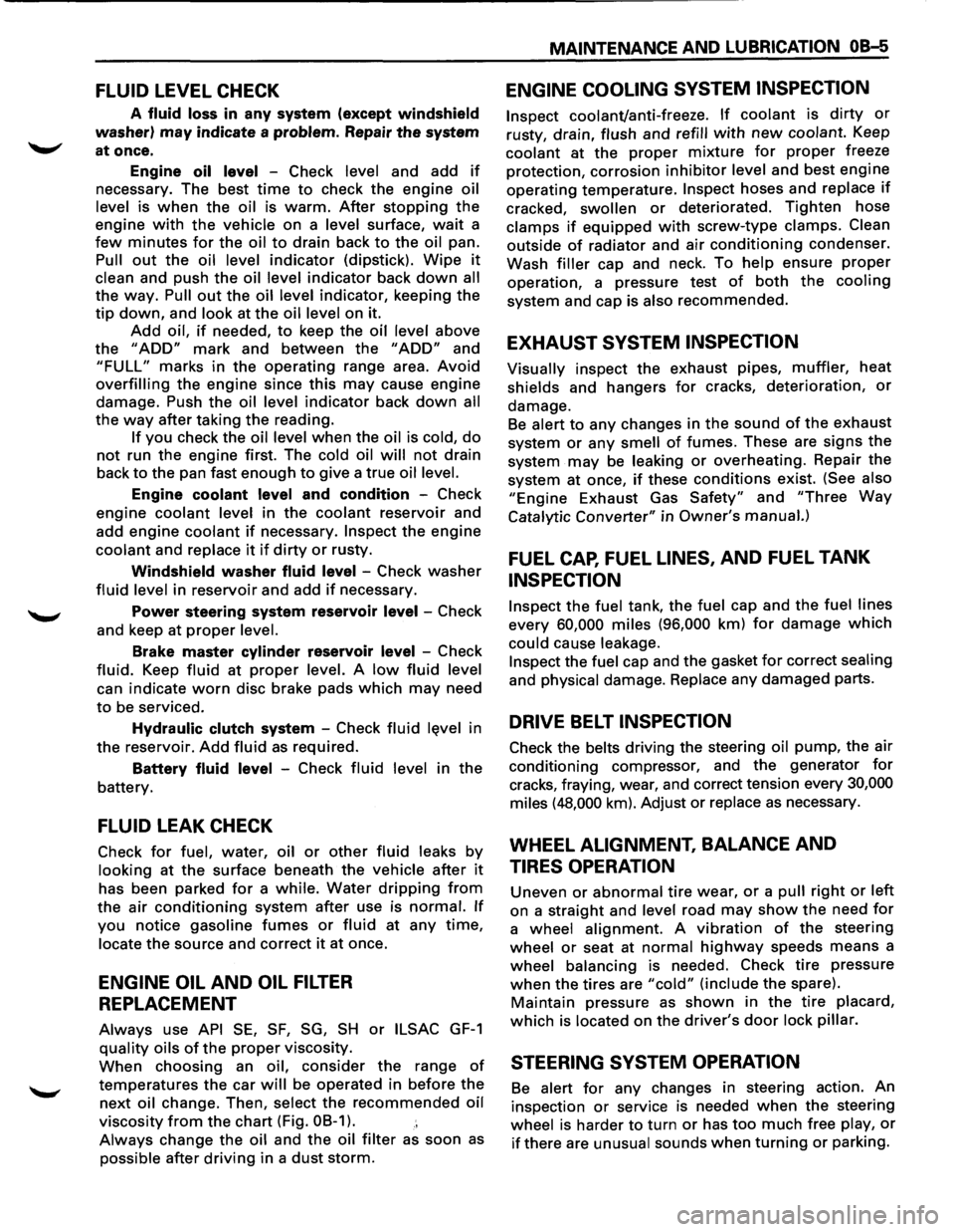
A fluid loss in any system (except windshield
washer) may indicate a problem. Repair the system
at once.
Engine
oil level -Check level and add if
necessary. The best time to check the engine oil
level is
when the oil is warm. After stopping the
engine with the vehicle on a level surface, wait a
few minutes for the oil to drain back to the oil pan.
Pull
out the oil level indicator (dipstick). Wipe it
clean and push the oil level indicator back down all
the
way. Pull out the oil level indicator, keeping the
tip down, and look at the oil level on it.
Add oil, if needed, to keep the oil level above
the
"ADD" mark and between the "ADD" and
"FULL" marks in the operating range area. Avoid
overfilling the engine since this may cause engine
damage. Push
the oil level indicator back down all
the
way after taking the reading.
If you check the oil level when the oil is cold, do
not run the engine first. The cold oil will not drain
back
to the pan fast enough to give a true oil level.
Engine coolant level and condition -Check
engine coolant level in the coolant reservoir and
add engine
coolant if necessary. Inspect the engine
coolant and replace it if dirty or rusty.
Windshield washer fluid level -Check washer
fluid level in reservoir and add if necessary.
Power steering system reservoir level-Check
and keep at
proper level.
Brake master cylinder reservoir level -Check
fluid. Keep fluid at proper level. A low fluid level
can indicate
worn disc brake pads which may need
to be serviced.
Hydraulic clutch system -Check fluid l~vel in
the reservoir.
Add fluid as required.
Battery fluid level -Check fluid level in the
battery.
FLUID LEAK CHECK
Check for fuel, water, oil or other fluid leaks by
looking at the surface beneath the vehicle after it
has been parked for a while. Water dripping from
the air conditioning system after use is normal. If
you notice gasoline fumes or fluid at any time,
locate the source and correct it at once.
ENGINE OIL AND OIL FILTER
REPLACEMENT
Always use API SE, SF, SG, SH or ILSAC GF-1
quality oils of the proper viscosity.
When choosing an oil, consider the range of
temperatures the car will be operated in before the
next oil change. Then, select the recommended oil
viscosity
from the chart (Fig. OB-1).
Always change the oil and the oil filter as soon as
possible after driving in a dust storm.
MAINTENANCE AND LUBRICATION OB-5
ENGINE COOLING SYSTEM INSPECTION
Inspect coolant/anti-freeze. If coolant is dirty or
rusty, drain, flush and refill with new coolant. Keep
coolant at the proper mixture for proper freeze
protection,
corrosion inhibitor level and best engine
operating temperature.
Inspect hoses and replace if
cracked, swollen or deteriorated. Tighten hose
clamps if equipped with screw-type clamps. Clean
outside of radiator and air conditioning condenser.
Wash
filler cap and neck. To help ensure proper
operation, a pressure test of both the cooling
system and cap is also recommended.
EXHAUST SYSTEM INSPECTION
Visually inspect the exhaust pipes, muffler, heat
shields and hangers
for cracks, deterioration, or
damage.
Be alert to any changes in the sound of the exhaust
system
or any smell of fumes. These are signs the
system may be leaking or overheating. Repair the
system at once,
if these conditions exist. (See also
"Engine Exhaust Gas Safety" and "Three Way
Catalytic Converter" in Owner's manual.)
FUEL CAP, FUEL LINES, AND FUEL TANK
INSPECTION
Inspect the fuel tank, the fuel cap and the fuel lines
every
60,000 miles (96,000 km) for damage which
could cause leakage.
Inspect the fuel cap and the gasket for correct sealing
and physical damage. Replace any damaged parts.
DRIVE BELT INSPECTION
Check the belts driving the steering oil pump, the air
conditioning compressor, and the generator
for
cracks, fraying, wear, and correct tension every 30,000
miles (48,000 km). Adjust or replace as necessary.
WHEEL ALIGNMENT, BALANCE AND
TIRES OPERATION
Uneven or abnormal tire wear, or a pull right or left
on a straight and level road may show the need for
a wheel alignment. A vibration of the steering
wheel or seat at normal highway speeds means a
wheel balancing is needed. Check tire pressure
when the tires are "cold" (include the spare).
Maintain pressure as shown in the tire placard,
which is located on the driver's door lock pillar.
STEERING SYSTEM OPERATION
Be alert for any changes in steering action. An
inspection
or service is needed when the steering
wheel is harder
to turn or has too much free play, or
if there are unusual sounds when turning or parking.
Page 29 of 1928
MAINTENANCE AND LUBRICATION OB-13
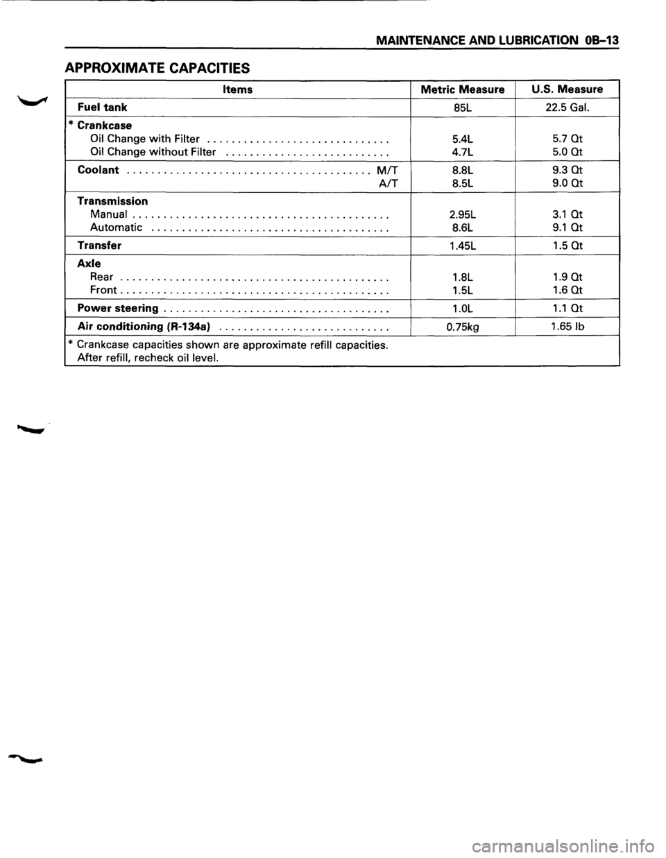
APPROXIMATE CAPACITIES
Items Metric Measure U.S. Measure
Fuel tank 85L 22.5 Gal.
*Crankcase
Oil Change with Filter .............................. 5.4L 5.7 at
Oil Change without Filter ••••••••••••••••••\
0 •••• 0 ••• 4.7L
5.0 at
Coolant ........................................ MIT 8.8L 9.3 at
A/T 8.5L 9.0 at
Transmission
Manual
.......................................... 2.95L 3.1 at
Automatic ••••••••••••••••••\
•• 0 •••• 0 0 0 ••••••••••• 8.6L 9.1 at
Transfer
1.45L 1.5 at
Axle
Rear o o o 0
0 0 0 0 0 0 0 0 0 0 0 0 0 0 0 0 I 0 0 0 o o o o o o o 0 0 0 0 0 0 0 0 0 0 0 o o 1.8L 1.9 at
Front ........................................ ~ ... 1.5L 1.6 at
Power steering ••• 0 ••••••••• 0 ••••••••••••••••••\
0 •••• 1.0L 1.1 at
Air conditioning (R-134a) o o 0
0 0 0 0 0 0 0 0 I 0 0 0 0 0 o o 0 o 0 0 0 0 0 0 0 0.75kg 1.651b
* Crankcase capacities shown are approximate refill capacities.
After
refill, recheck oil level.
Page 500 of 1928
6-2 ENGINE DIAGNOSIS
SECTION 6E-DRIVEABILITY
AND EMISSIONS
This section covers emission control systems general
information, and diagnostic procedures which will lead
to repairing performance and driveability related
problems.
Emission components are covered, as well
as removal and replacement procedures.
Instructions on use
of special tools are also given.
SECTION 6F-ENGINE EXHAUST
This section has information on all exhaust system
parts, such
as tailpipes, mufflers, and the catalytic
converter.
GENERAL DESCRIPTION
ENGINE CLEANLINESS AND CARE
An automobile engine is a combination of many
machined, honed,
polished and lapped surfaces with
tolerances that are measured in the thousandths of a
millimeter (ten thousandths of an inch). Accordingly,
when any
internal engine parts are serviced, care and
cleanliness are important. Throughout this section, it
should be understood that proper cleaning and
protection
of machined surfaces and friction areas is
part
of the repair procedure. This is considered
standard shop practice even
if not specifically stated.
• A liberal coating of engine oil should be applied to
all friction areas during assembly to protect and
lubricate the surfaces on initial operation.
• Whenever valve train components, pistons, piston
rings, connecting rods, rod bearings, and
crankshaft
journal bearings are removed for
service, they should be retained in order.
• At the time of installation, they should be installed
in the same locations and with the same mating
surfaces
as when removed.
• Battery cables should be disconnected before any
major
work is performed on the engine. Failure to
disconnect
cables may result in damage to wire
harness
or other electrical parts.
• The six cylinders of this engine are identified by
numbers; Right side
cylinders 1, 3 and 5, Left side
cylinders 2, 4 and 6, as counted from crankshaft
pulley side to flywheel side.
GENERAL INFORMATION ON ENGINE
SERVICE
The following information on engine service should be
noted
carefully, as it is important in preventing damage
and contributing
to reliable engine performance.
• When raising or supporting the engine for any
reason,
do not use a jack under the oil pan. Due to
the
small clearance between the oil pan and the oil
pump strainer, jacking against the oil pan may
cause damage to the
oil pick-up unit.
• The 12-volt electrical system is capable of
damaging circuits. When performing any work
where electrical terminals could possibly be
grounded, the ground cable of the battery should
be disconnected at the battery.
• Any time the intake air duct or air cleaner is
removed, the intake opening
should be covered.
This
will protect against accidental entrance of
foreign material into the cylinder which could
cause extensive damage when the engine is
started.
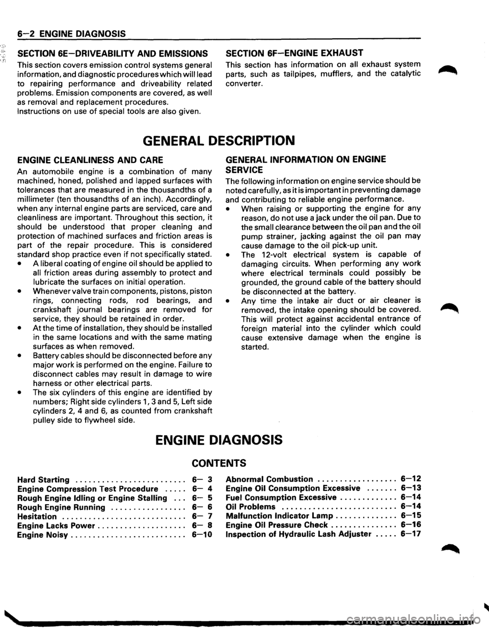
ENGINE DIAGNOSIS
CONTENTS
Hard Starting . . . . . . . . . . . . . . . . . . . . . . . . . 6-3
Engine Compression
Test Procedure ..... 6-4
Rough Engine
Idling or Engine Stalling . . . 6-5
Rough Engine Running . . . . . . . . . . . . . . . . .
6-6
Hesitation . . . . . . . . . . . . . . . . . . . . . . . . . . . . 6-7
Engine Lacks
Power . . . . . . . . . . . . . . . . . . . . 6-8
Engine
Noisy .......................... 6-10
Abnormal Combustion . . . . . . . . . . . . . . . . . . 6-12
Engine Oil Consumption Excessive . . . . . . . 6-13
Fuel Consumption Excessive ............. 6-14
Oil Problems . . . . . . . . . . . . . . . . . . . . . . . . . . 6-14
Malfunction Indicator Lamp . . . . . . . . . . . . . . 6-15
Engine Oil Pressure Check ............... 6-16
Inspection of Hydraulic Lash Adjuster . . . . . 6-17
Page 561 of 1928
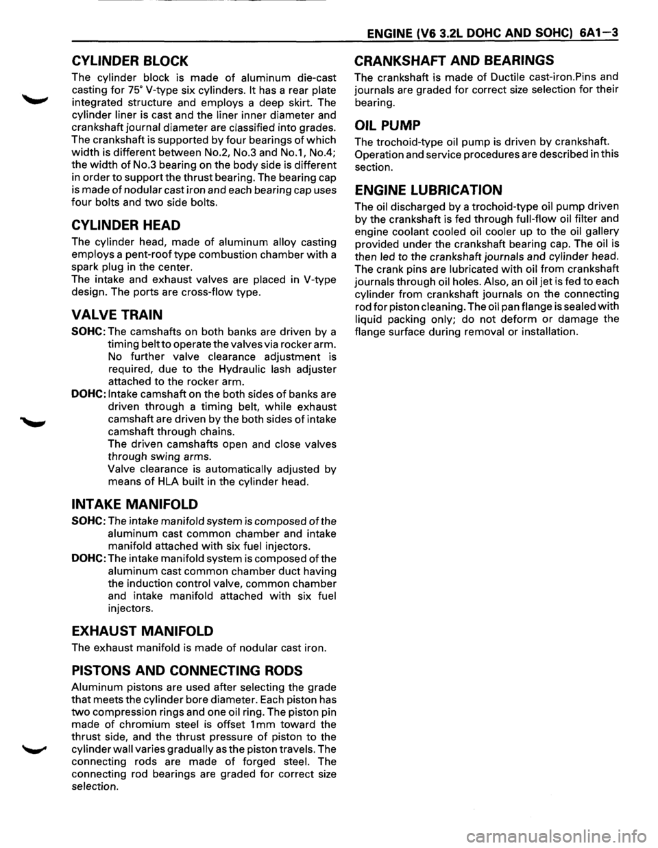
CYLINDER BLOCK
The cylinder block is made of aluminum die-cast
casting
for 75° V-type six cylinders. It has a rear plate
integrated structure and employs a deep skirt. The
cylinder liner is cast and the liner inner diameter and
crankshaft
journal diameter are classified into grades.
The crankshaft is supported by four bearings
of which
width is different between No.2, No.3 and No.1, No.4;
the
width of No.3 bearing on the body side is different
in order
to support the thrust bearing. The bearing cap
is made
of nodular cast iron and each bearing cap uses
four bolts and two side bolts.
CYLINDER HEAD
The cylinder head, made of aluminum alloy casting
employs a pent-roof type combustion chamber with a
spark
plug in the center.
The intake and exhaust
valves are placed in V-type
design. The ports are cross-flow type.
VALVE TRAIN
SOHC: The camshafts on both banks are driven by a
timing
belt to operate the valves via rocker arm.
No
further valve clearance adjustment is
required, due
to the Hydraulic lash adjuster
attachedtotherockerarm.
DOHC: Intake camshaft on the both sides of banks are
driven through a
timing belt, while exhaust
camshaft are driven by the both sides
of intake
camshaft through chains.
The driven camshafts open and
close valves
through swing arms.
Valve clearance is automatically adjusted by
means
of HLA built in the cylinder head.
INTAKE MANIFOLD
SOHC: The intake manifold system is composed ofthe
aluminum cast common chamber and intake
manifold attached with six fuel injectors.
DOHC: The intake manifold system is composed of the
aluminum cast common chamber duct having
the induction
control valve, common chamber
and intake
manifold attached with six fuel
injectors.
EXHAUST MANIFOLD
The exhaust manifold is made of nodular cast iron.
PISTONS AND CONNECTING RODS
Aluminum pistons are used after selecting the grade
that meets the cylinder bore diameter. Each piston has
two compression rings and one oil ring. The piston pin
made
of chromium steel is offset 1 mm toward the
thrust side, and the thrust pressure
of piston to the
cylinder wall varies gradually as the piston travels. The
connecting rods are made
of forged steel. The
connecting rod bearings are graded
for correct size
selection.
ENGINE (V6 3.2L DOHC AND SOHC) 6A1-3
CRANKSHAFT AND BEARINGS
The crankshaft is made of Ductile cast-iron.Pins and
journals are graded for correct size selection for their
bearing.
OIL PUMP
The trochoid-type oil pump is driven by crankshaft.
Operation and service procedures are described in this
section.
ENGINE LUBRICATION
The oil discharged by a trochoid-type oil pump driven
by the crankshaft is fed through full-flow oil filter and
engine
coolant cooled oil cooler up to the oil gallery
provided under the crankshaft bearing cap. The oil is
then
led to the crankshaft journals and cylinder head.
The crank pins are
lubricated with oil from crankshaft
journals through oil holes. Also, an oil jet is fed to each
cylinder from crankshaft journals on the connecting
rod
for piston cleaning. The oil pan flange is sealed with
liquid packing only; do not deform or damage the
flange surface during removal or installation.
Page 567 of 1928
Nuts
~~~ Torque N·m (lb·ft) 24 (17)
13. Exhaust Gas Recirculation Valve assembly
• Tighten bolts to the specified torque.
Exhaust Gas Recirculation
Valve Side
~~~ Torque N·m (lb·in) I 8 (69)
Exhaust Manifold Side
~~~ Torque N·m (lb·ft) 28 (21)
12. Evaporative Emission Canister Purge hose
11. Positive Crankcase Vantilatlon hose
10. Fuel Pressure Control Valve vacuum hose
8. Throttle body
• Tighten bolts to the specified torque.
~~~ Torque N·m (lb·ft) I 19 (14)
9. Vacuum hose
• Connect vacuum hoses on canister Vacuum
Switching Valve
and Exhaust Gas Recirculation
Vacuum Switching Valve to the throttle body.
7. Ignition Control Module assembly
• Tighten bolts to the specified torque and
connect connector.
~~~ Torque N·m (lb·ft)
6. High tension cables
5. Connectors
• Connect each connector.
4. Vacuum booster hose
3. Canister vacuum hose
2. Accelerator Pedal cable
19 (14)
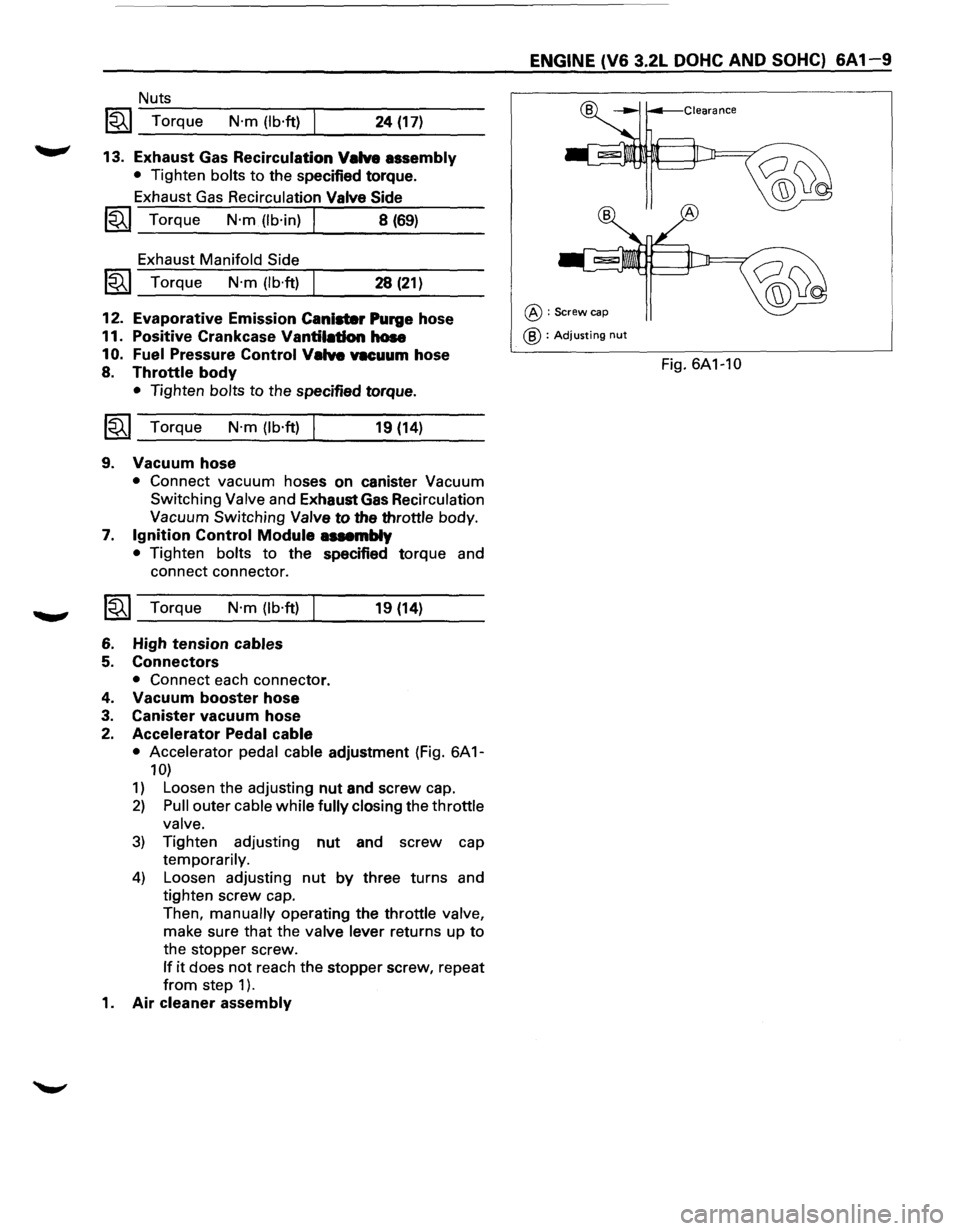
• Accelerator pedal cable adjustment (Fig. 6A 1-
10)
1) Loosen the adjusting nut and screw cap.
2) Pull outer cable while fully closing the throttle
valve.
3) Tighten adjusting nut and screw cap
temporarily.
4) Loosen adjusting nut by three turns and
tighten screw cap.
Then,
manually operating the throttle valve,
make sure that the valve lever returns up to
the stopper screw.
If it does not reach the stopper screw, repeat
from step 1 ).
1. Air cleaner assembly
ENGINE (V6 3.2L DOHC AND SOHC) 6A 1-9
@:Screw cap
@ : Adjusting nut
Fig. 6A1-10
Page 569 of 1928
I••IINSTALLATION
13. Common chamber
~ • Tighten bolts and nuts to the specified torque.
~
Bolts
1~1 Torque N·m (lb·ft) 24 (17)
Nut
~~~ Torque N·m (lb·ft) 24 (17)
12. Exhaust Gas Recirculation Valve assembly
• Tighten bolts to the specified torque.
~~~ Torque N·m (lb·in) I 9 (78)
11. Evaporative Emission Canister Purge hose
9. Positive Crankcase Ventilation hose
1
0. Fuel Pressure Control Valve vacuum hose
7. Throttle body
• Tighten bolts to the specified torque.
~~~ Torque N·m (lb·ft) I 22 (16)
8. Vacuum hose
6.
~
5.
4.
3.
2.
• Connect vacuum hoses on canister Vacuum
Switching Valve and Exhaust
Gas Recirculation
Vacuum Switching Valve to the Throttle Body.
Ignition Control Module assembly
• Tighten bolts to the specified torque and
connect connector.
Torque
N·m (lb·ft)
High tension cables
Connectors
22 (16)
• Connect each connector without fail.
Vacuum booster hose
Accelerator Pedal cable
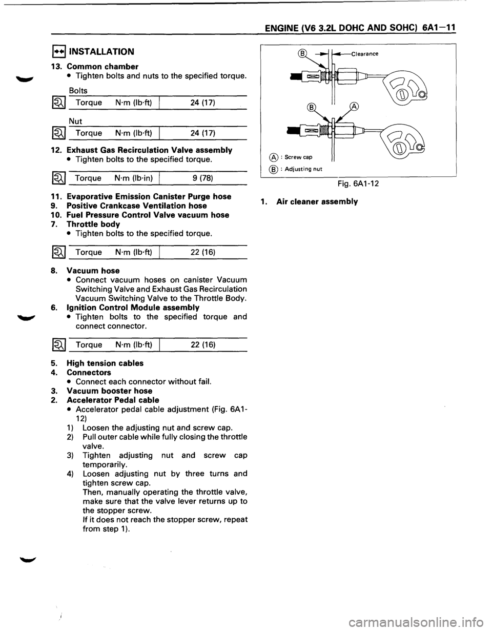
• Accelerator pedal cable adjustment (Fig. 6A 1-
12)
1) Loosen the adjusting nut and screw cap.
2) Pull outer cable while fully closing the throttle
valve.
3) Tighten adjusting nut and screw cap
temporarily.
4) Loosen adjusting nut by three turns and
tighten screw cap.
Then, manually operating the throttle valve,
make sure that the valve lever returns up to
the stopper screw.
If it does not reach the stopper screw, repeat
from step 1 ).
ENGINE (V6 3.2L DOHC AND SOHC) 6A1-11
@:Screw cap
@ :Adjusting nut
Fig. 6A1-12
1. Air cleaner assembly
Page 571 of 1928
l·u·IINSTALLATION
16. Common chamber
• Tighten bolts and nuts to the specified torque.
Bolts
1«1 Torque N·m (lb·ft) 24 (17)
Nuts
1«1 Torque N·m (lb·ft) 24 (17)
15. Throttle body
• Connect the water hose securely.
14. Common chamber duct
• Tighten bolts and nuts to the specified torque.
Bolts
~ Torque N·m (lb·ft) 24 (17)
Nuts
~ Torque N·m (lb·ft) 24 (17)
13. Exhaust Gas Recirculation Valve assembly
• Tighten bolts to the specified torque.
Exhaust Gas Recirculation Valve
Side
1«1 Torque N·m (lb·in) I 8 (69)
Exhaust Manifold Side
1«1 Torque N·m (lb·ft) 28 (21)
12. Evaporative Emission Canister Purge hose
11. Positive Crankcase Ventilation hose
10. Fuel Pressure Control Valve vacuum hose
8. Throttle body
• Tighten bolts to the specified torque.
1«1 Torque N·m (lb·ft) I 19 (14)
9. Vacuum hose
• Connect vacuum hoses on canister Vacuum
Switching Valve and Exhaust Gas Recirculation
Vacuum
Switching Valve to the throttle body.
7. Ignition Control Module assembly
• Tighten bolts to the specified torque and
connect connector.
1«1 Torque N·m (lb·ft)
6. High tension cables
5. Connectors
• Connect each connector.
4. Vacuum booster hose
3. Canister vacuum hose
19 (14)
ENGINE (V6 3.2L DOHC AND SOHC) 6A 1-13
2. Accelerator Pedal cable
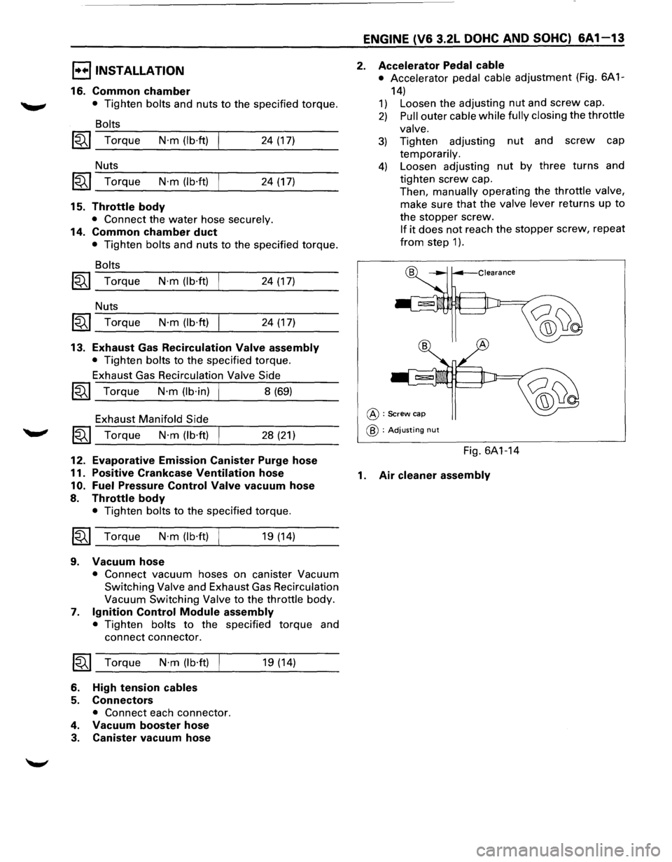
• Accelerator pedal cable adjustment (Fig. 6A 1-
14)
1) Loosen the adjusting nut and screw cap.
2) Pull outer cable while fully closing the throttle
valve.
3) Tighten adjusting nut and screw cap
temporarily.
4) Loosen adjusting nut by three turns and
tighten screw cap.
Then, manually operating the
throttle valve,
make sure that the valve lever returns up to
the stopper screw.
If it does not reach the stopper screw, repeat
from step 1 ).
@:Screw cap
@ : Adjusting nut
Fig. 6A1-14
1. Air cleaner assembly
Page 573 of 1928
16. Intake manifold
• Remove two fixing bolts and four nuts, then
remove the intake
manifold.
I••IINSTALLATION
16. Intake manifold
• Tighten bolts and nuts to the specified torque.
Bolts
~~~ Torque N·m (lb·ft) 24 (17)
Nuts
1~1 Torque N·m (lb·ft) 24 (17)
15. Connectors
• Connect each connector.
14. Fuel hoses
• Connect the hoses securely and install bolts on
the head cover.
13. Common chamber
• Tighten bolts and nuts to the specified torque.
Bolts
~~~ Torque N·m (lb·ft) 24 (17)
Nuts
~~~ Torque N·m (lb·ft) 24 (17)
12. Exhaust Gas Recirculation Valve assembly
• Tighten bolts to the specified torque.
~~~ Torque N·m (lb·in) I 9 (78)
11. Evaporative Emission Canister Purge hose
10. Fuel Pressure Control Valve vacuum hose
9. Positive Crankcase Ventilation hose
7. Throttle body
• Tighten bolts to the specified torque.
~~~ Torque N·m (lb·ft) I 22 (16)
8. Vacuum hose
• Connect vacuum hoses on canister Vacuum
Switching Valve and Exhaust Gas Recirculation
Vacuum
Switching Valve to the throttle body.
6. Ignition Control Module assembly
• Tighten bolts to the specified torque and
connect connector.
~~~ Torque N·m (lb·ft) 22 (16)
5. High tension cables
4. Connectors
• Connect each connector without fail.
3. Vacuum booster hose
ENGINE (V6 3.2L DOHC AND SOHC) 6A1-15
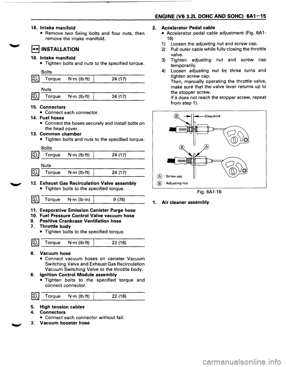
2. Accelerator Pedal cable
• Accelerator pedal cable adjustment (Fig. 6A 1-
16)
1) Loosen the adjusting nut and screw cap.
2) Pull outer cable while fully closing the throttle
valve.
3) Tighten adjusting nut and screw cap
temporarily.
4) Loosen adjusting nut by three turns and
tighten
screw cap.
Then,
manually operating the throttle valve,
make sure that the valve lever returns up to
the stopper screw.
If it does not reach the stopper screw, repeat
from step 1 ).
@:Screw cap
@ : Adjusting nut
Fig. 6A1-16
1. Air cleaner assembly
Page 575 of 1928
... t&:?
17. Fuel hoses
• Disconnect feed and return fuel hoses from fuel
pipes, and remove
two bracket fixing bolts on
the cylinder head cover.
18. Fuel injector connectors
• Disconnect from injectors.
19. Intake manifold
• Remove engine harness bracket on RH side.
• Remove two bolts and four nuts, and remove
intake manifold.
I••IINSTALLATION
19. Intake manifold
• Tighten bolts and nuts to the specified torque.
Bolts
~~~ Torque N·m (lb·ft) 24 (17)
Nuts
~~~ Torque N·m (lb·ft) 24 (17)
18. Fuel injector connectors
• Connect each connector.
17. Fuel hoses
• Connect the hoses securely and install the bolts
on the head cover.
16. Common chamber
• Tighten bolts and nuts to the specified torque.
Bolts
~ Torque N·m (lb·ft) 24 (17)
Nuts
~ Torque N·m (lb·ft) 24 (17)
15. Throttle body
• Connect surely the water hose.
14. Common chamber duct
• Tighten bolts and nuts to the specified torque.
Bolts
~ Torque N·m (lb·ft) 24 (17)
Nuts
~ Torque N·m (lb·ft) 24 (17)
13. Exhaust Gas Recirculation Valve assembly
• Tighten bolts to the specified torque.
Exhaust Gas Recirculation Valve
Side
~~~ Torque N·m (lb·in) I 8 (69)
Exhaust Manifold Side
~~~ Torque N·m (lb·ft) 28 (21)
12. Evaporative Emission Canister Purge hose
11. Positive Crankcase
Ventilation hose
10. Fuel Pressure Control Valve vacuum hose
ENGINE (V6 3.2L DOHC AND SOHC) 6A1-17
8. Throttle body
• Tighten bolts to the specified torque.
~~~ Torque N·m (lb·ft) I 19 (14)
9. Vacuum hose
• Connect vacuum hoses on canister Vacuum
Switching Valve and Exhaust Gas Recirculation
Vacuum Switching Valve
to the throttle body.
7. Ignition Control Module assembly
• Tighten bolts to the specified torque and
connect connector.
~~~ Torque N·m (lb·ft) 19 (14)
6. High tension cables
5. Connectors
• Connect each connector without fail.
4. Vacuum booster hose
3. Canister vacuum hose
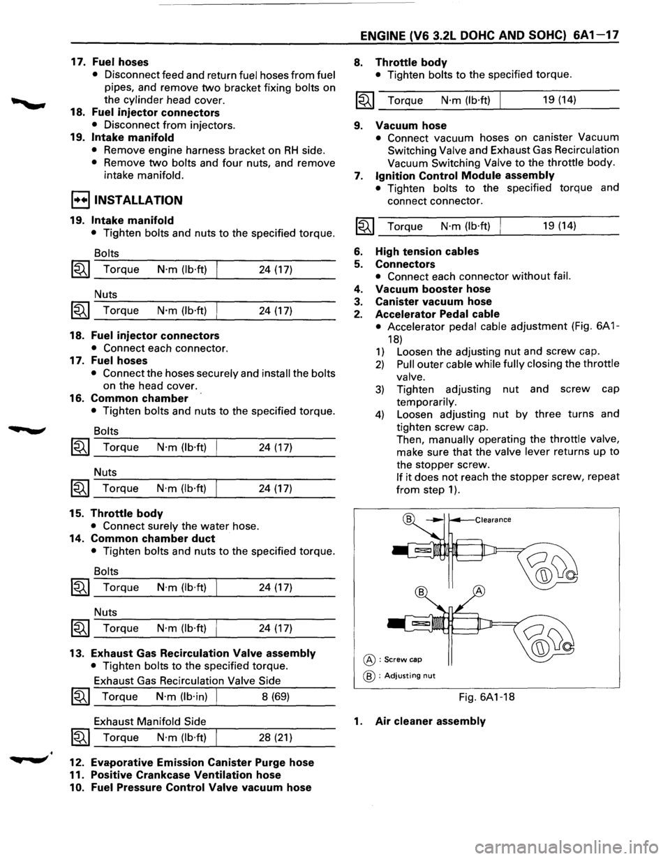
2. Accelerator Pedal cable
• Accelerator pedal cable adjustment (Fig. 6A 1-
18)
1) Loosen the adjusting nut and screw cap.
2) Pull outer cable while fully closing the throttle
valve.
3) Tighten adjusting nut and screw cap
temporarily.
4) Loosen adjusting nut by three turns and
tighten screw cap .
Then, manually operating the throttle valve,
make sure
that the valve lever returns up to
the stopper screw.
If it does not reach the stopper screw, repeat
from step 1 ).
@:Screw cap
@ : Adjusting nut
Fig. 6A1-18
1. Air cleaner assembly