relay ISUZU TROOPER 1995 Workshop Manual
[x] Cancel search | Manufacturer: ISUZU, Model Year: 1995, Model line: TROOPER, Model: ISUZU TROOPER 1995Pages: 1928
Page 35 of 1928
~~[II] BODY ENG. FRAME
HEATING AND VENTILATION 1A-5
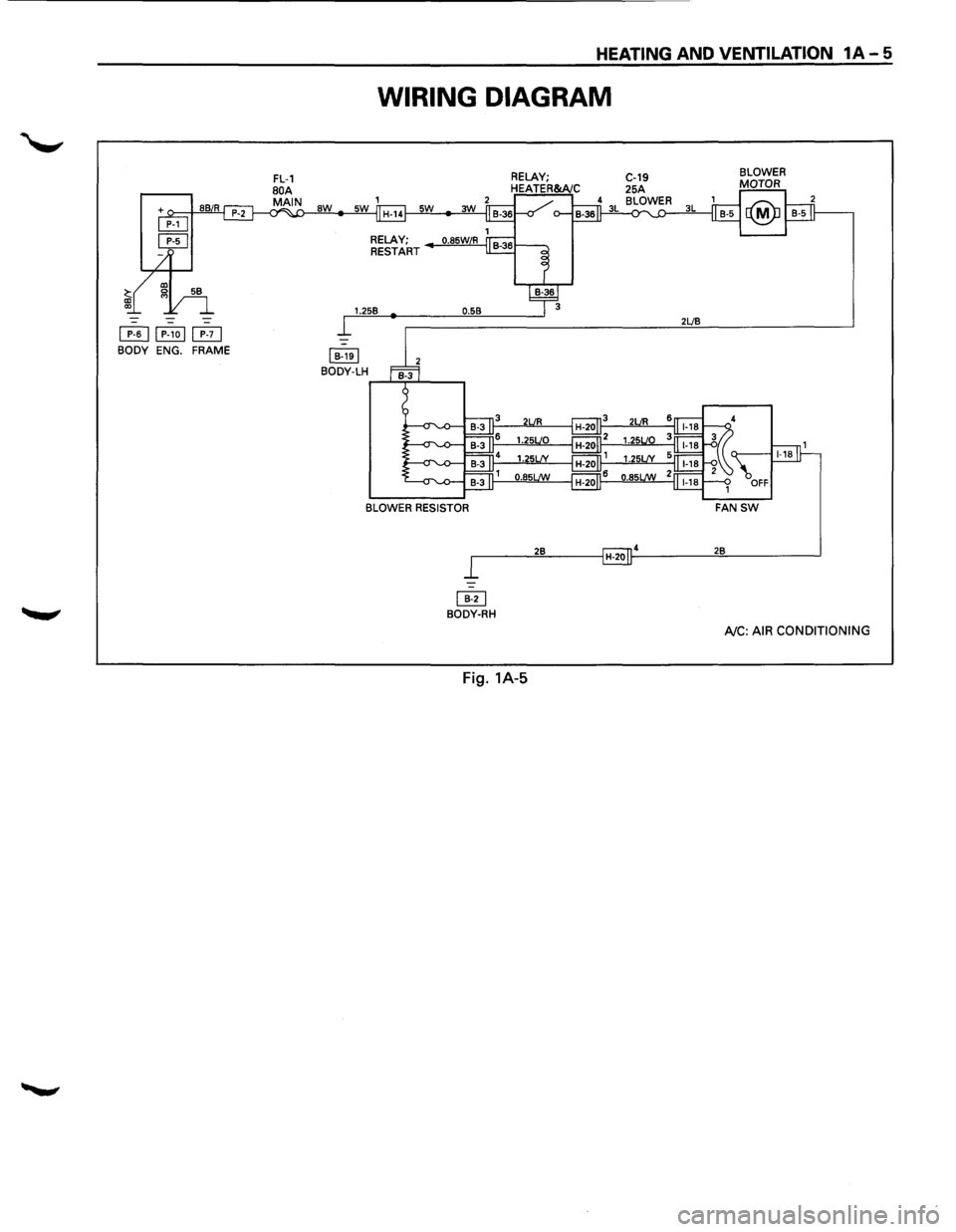
WIRING DIAGRAM
aw
RELAY;
RESTART
1.258
I 8-1el BODY-LH
0.58 2LJ8
BLOWER RESISTOR
r------'2::.::8:,__ __ _,H-201~4 ____ __,2""8 _____ __,
~ BODY-RH
AJC: AIR CONDITIONING
Fig. 1A-5
Page 37 of 1928
FAN CONTROL LEVER (FAN SWITCH)
DIAGNOSIS
HEATING AND VENTILATION 1A-7
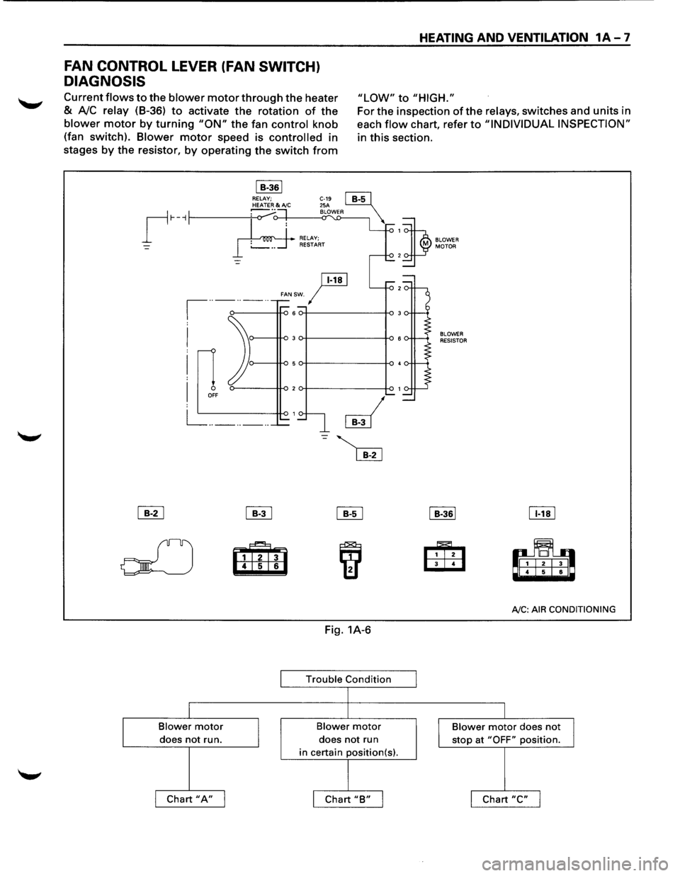
Current flows to the blower motor through the heater
& A!C relay (8-36) to activate the rotation of the
blower motor by turning "ON" the fan control knob
(fan switch).
Blower motor speed is controlled in
stages
by the resistor, by operating the switch from
"LOW" to "HIGH."
I B-361 RELAY;
ji!!J
For the inspection of the relays, switches and units in
each
flow chart, refer to "INDIVIDUAL INSPECTION"
in this section.
1
)
BLOWER MOTOR 2
r-··-··-··
FANSW. I
I
I
I
0 OFF
L= _______ _
~ ~
olJ m 6
I
Blower motor
I does not run.
I Chart "A" I
~
iif1
Fig. 1A-6
Trouble Condition
I
l
Blower motor
does not run
in certain position(s).
I
I Chart "B" I I
BLOWER RESISTOR
I B-361
Eili3 4
IT!!]
rl! 6
AJC: AIR
CONDITIONING
I
Blower motor does not
J stop at "OFF" position.
I Chart "C" I
Page 40 of 1928
1A-10 HEATING AND VENTILATION
~ INDIVIDUAL INSPECTION
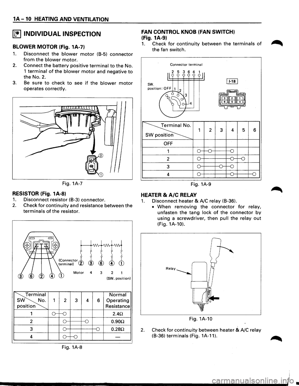
BLOWER MOTOR (Fig. 1A-7)
1. Disconnect the blower motor (B-5) connector
from the blower motor.
2. Connect the battery positive terminal to the No.
1 terminal of the blower motor and negative to
the No.2.
3. Be sure to check to see if the blower motor
operates correctly.
Fig. 1A-7
RESISTOR (Fig. 1A-8)
1. Disconnect resistor (B-3) connector.
2. Check for continuity and resistance between the
terminals of the resistor.
Motor 4 3 2
(SW. position)
Terminal Normal
SW No.
2 3 4 6 Operating
position Resistance
1 2.4Q
2 0.90Q
3 0.28Q
4
Fig. 1A-8
FAN CONTROL KNOB (FAN SWITCH)
(Fig. 1A-9)
1. Check for continuity between the terminals of
the fan switch.
Connector terminal
2 3 4 5 6
OFF
1
2
3
4
Fig. 1A-9
HEATER & A/C RELAY
1. Disconnect heater & A!C relay (B-36).
• When removing the connector for relay,
unfasten the tang lock of the connector by
using a screwdriver, then pull the relay out
(Fig. 1A-10).
Fig. 1A-10
2. Check for continuity between heater & A!C relay
(B-36) terminals (Fig. 1A-11).
~
•
Page 60 of 1928
1 B-6 AIR CONDITIONING
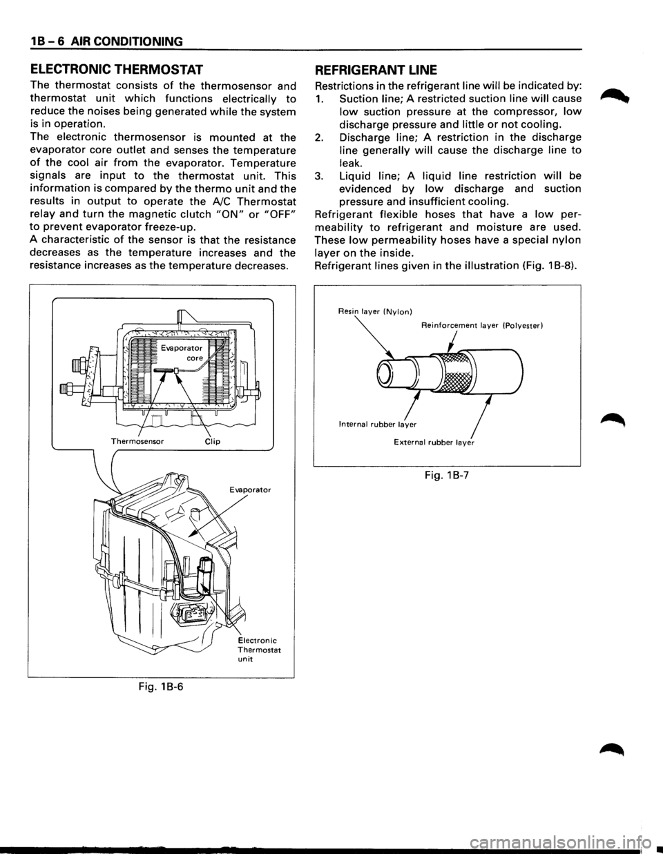
ELECTRONIC THERMOSTAT
The thermostat consists of the thermosensor and
thermostat unit which functions electrically to
reduce the noises being generated while the system
is in operation.
The
electronic thermosensor is mounted at the
evaporator core outlet and senses the temperature
of the cool air from the evaporator. Temperature
signals are input to the thermostat unit. This
information is compared by the thermo unit and the
results in output to operate the A/C Thermostat
relay and turn the magnetic clutch "ON" or "OFF"
to prevent evaporator freeze-up.
A characteristic
of the sensor is that the resistance
decreases as the
temperature increases and the
resistance increases as
the temperature decreases.
Thermosensor Clip
Evaporator
unit
Fig. 18-6
REFRIGERANT LINE
Restrictions in the refrigerant line will be indicated by:
1. Suction line; A restricted suction line will cause
low suction pressure at the compressor, low
discharge pressure and little or not cooling.
2. Discharge line; A restriction in the discharge
line generally will cause the discharge line to
leak.
3. Liquid line; A liquid line restriction will be
evidenced
by low discharge and suction
pressure and
insufficient cooling.
Refrigerant flexible hoses that have a low per
meability to refrigerant and moisture are used.
These
low permeability hoses have a special nylon
layer on the inside.
Refrigerant
lines given in the illustration (Fig. 1 B-8).
Resin layer (Nylon)
Reinforcement layer (Polyester)
External rubber layer
Fig. 1 B-7
•
Page 61 of 1928
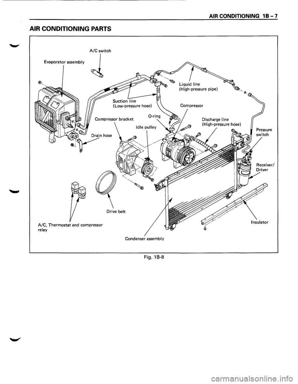
AIR CONDITIONING PARTS
A/C switch
Evaporator
assembly
J
Drive belt
A/C,
Thermostat and compressor relay
Condenser assembly
Fig. 1 B-8
AIR CONDITIONING 1 B - 7
Insulator
Page 62 of 1928
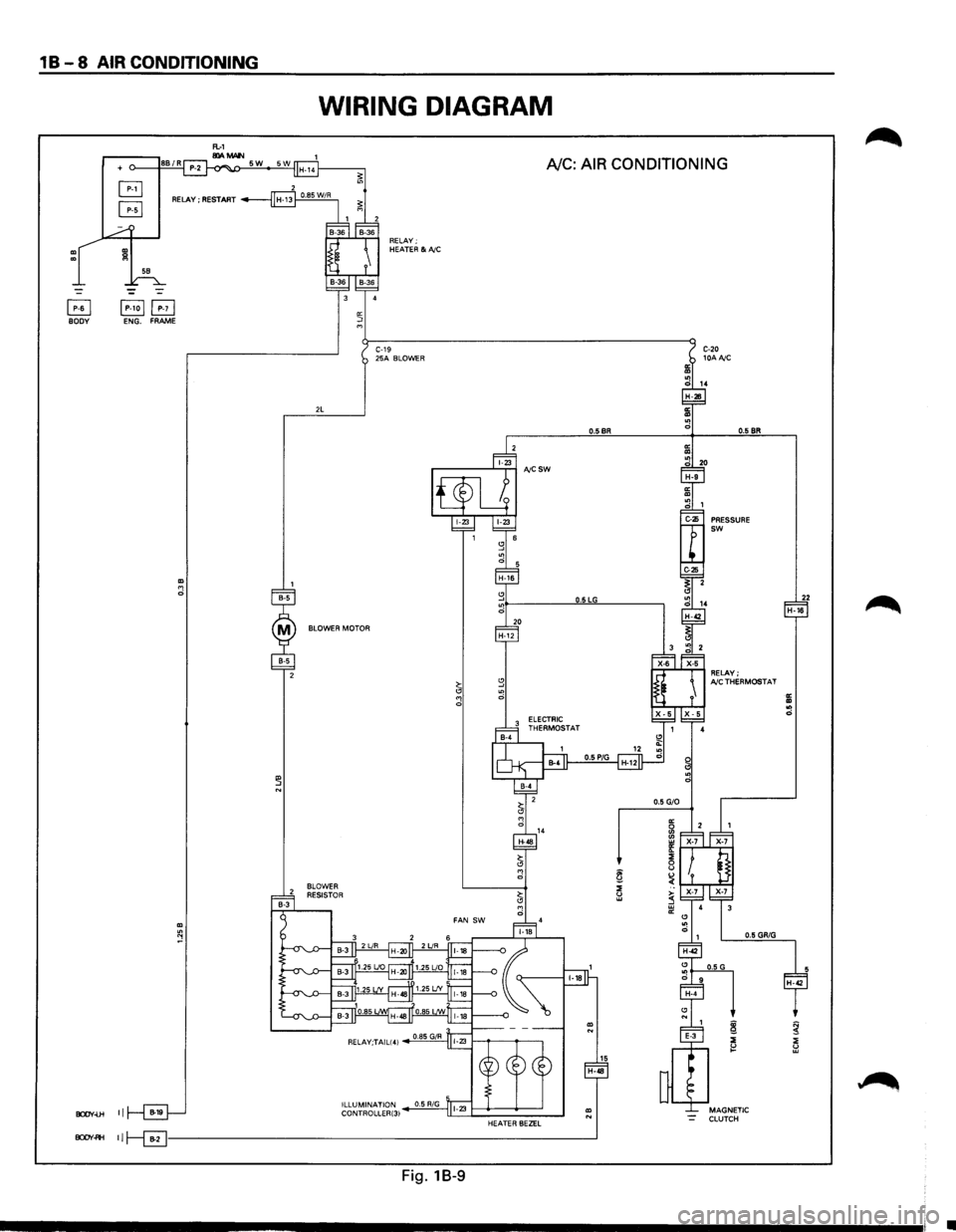
1 B - 8 AIR CONDITIONING
+
RELAY; RESTART
~ ~B BOOV ENG. FRAME
BOOV-Ui II
WIRING DIAGRAM
RELAY; HEATER &NC
A/C: AIR CONDITIONING
BOOV~ 11~--------------------------------------------------------------_j
Fig. 18-9
•
Page 68 of 1928
18-14 AIR CONDITIONING
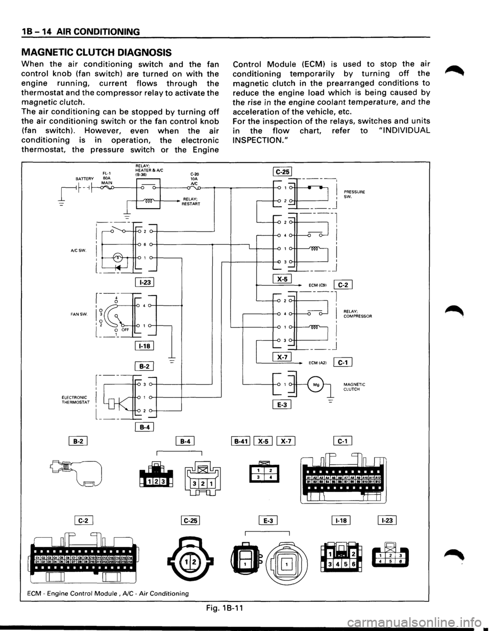
MAGNETIC CLUTCH DIAGNOSIS
When the air conditioning switch and the fan
control knob (fan switch) are turned on with the
engine running, current flows through the
thermostat and the compressor relay to activate the
magnetic clutch.
The air conditioning can be stopped by turning off
the air conditioning switch or the fan control knob
(fan switch). However, even when the air
conditioning is in operation, the electronic
thermostat, the pressure switch or the Engine
BATTER y
~
A/C SW.
FAN SW.
FL-1 BOA MAIN -.Y""'
I
RELAY; HEATER&A/C (8-36)
-
·~
~-----;::: -
I ,--<> -v--ro 2
I 6
! -&r ro 1 l ~ .... --~-'---
11-231
r-g-I 4
I~ 0 I 2 1
l __ 9_ OFF -
lli!J
~
r-----3 I
I 1
I 2 -
ELECTRONIC ~ THERMOSTAT
l __ _
C-20 10A Jd.C
RELAY; RESTART
-=-
ECM -Engine Control Module , NC -Air Conditioning
Control Module (ECM) is used to stop the air
conditioning temporarily by turning off the
magnetic clutch in the prearranged conditions to
reduce the engine load which is being caused by
the rise in the engine coolant temperature, and the
acceleration of the vehicle, etc.
For
the inspection of the relays, switches and units
in the flow chart, refer to "INDIVIDUAL
INSPECTION."
,....-1
2 ......_
.....-=.-2
40. r-
1v-
3
......._ =--
~
I ___ j
PRESSURE
SW.
ECMIC91
~
---2 ----l
•o--
1v-
3
-~-@]
~1
L
[ill
I
I RELAY; COMPRESSOR
I
I I ___ j
ECMIA21 ~
:=:>
MAGNETIC
CLUTCH
,.----I In_ r-r
A1 Kl ., .. ...... A& .. A7 AI ld A10 A11A12 .... •• ., .. a1o an 112
'It!
~
~
Fig.1B-11
Page 69 of 1928
AIR CONDITIONING 1 B -15
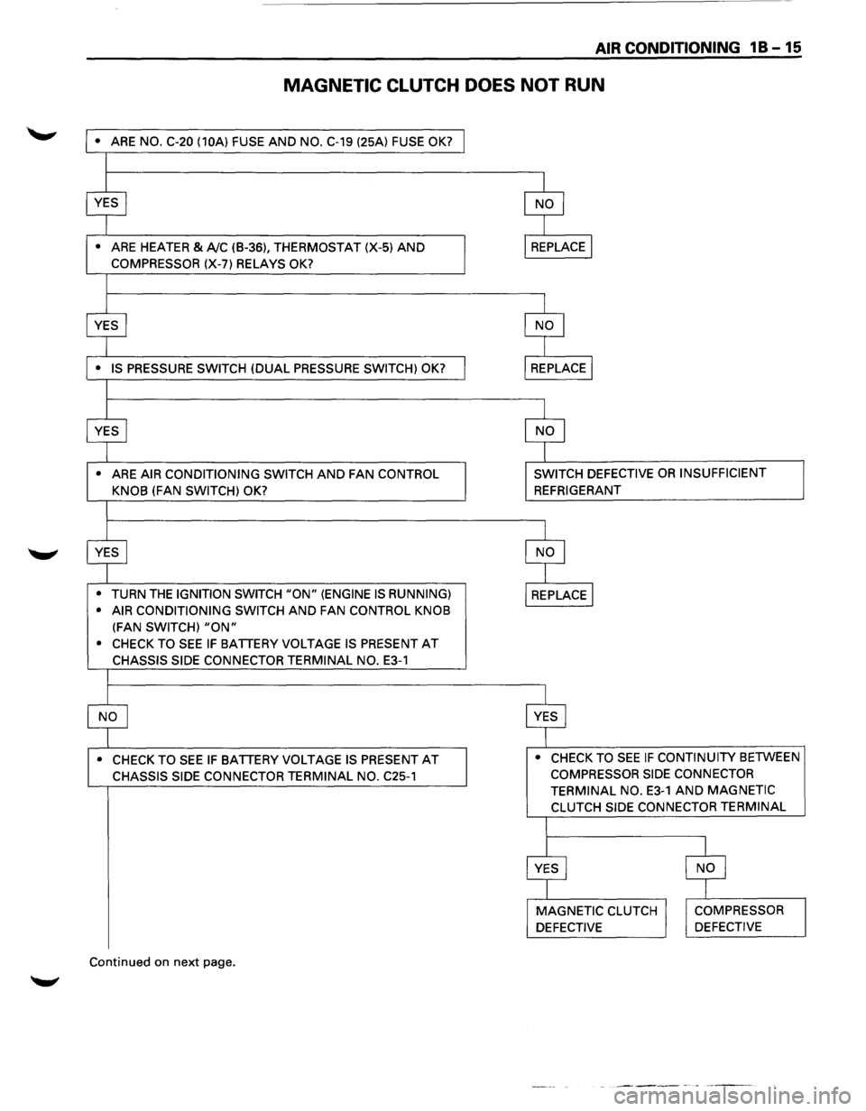
MAGNETIC CLUTCH DOES NOT RUN
• ARE NO. C-20 (10A) FUSE AND NO. C-19 (25A) FUSE OK?
•
ARE HEATER & A!C (B-36), THERMOSTAT (X-5) AND
COMPRESSOR (X-7) RELAYS OK?
•
ARE AIR CONDITIONING SWITCH AND FAN CONTROL
KNOB
(FAN SWITCH) OK?
•
TURN THE IGNITION SWITCH "ON" (ENGINE IS RUNNING)
• AIR CONDITIONING SWITCH
AND FAN CONTROL KNOB
(FAN SWITCH) "ON"
• CHECK TO SEE IF BATTERY VOLTAGE IS PRESENT AT
CHASSIS SIDE CONNECTOR TERMINAL NO. E3-1
• CHECK TO SEE IF BATTERY VOLTAGE IS PRESENT AT
CHASSIS SIDE CONNECTOR TERMINAL NO. C25-1
Continued on next page.
SWITCH DEFECTIVE OR INSUFFICIENT
REFRIGERANT
• CHECK TO
SEE IF CONTINUITY BETWEEN
COMPRESSOR SIDE CONNECTOR
TERMINAL NO.
E3-1 AND MAGNETIC
CLUTCH SIDE CONNECTOR TERMINAL
Page 70 of 1928
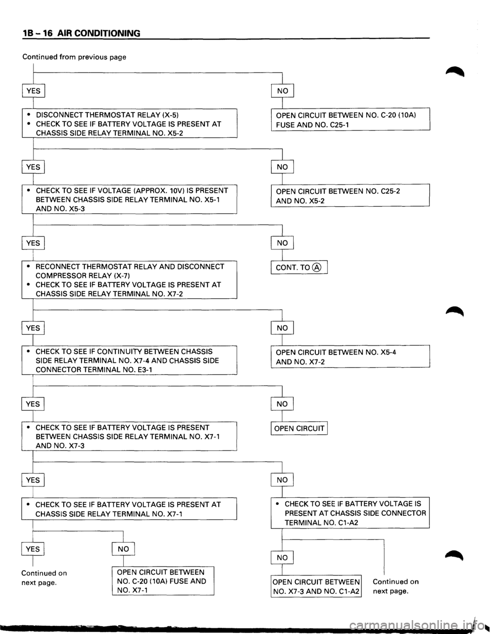
1 B -16 AIR CONDITIONING
Continued from previous page
• DISCONNECT THERMOSTAT RELAY (X-5)
• CHECK TO SEE IF BATTERY VOLTAGE IS PRESENT AT
CHASSIS SIDE RELAY TERMINAL NO. X5-2
• CHECK TO SEE IF VOLTAGE (APPROX. 10V) IS PRESENT
BETWEEN CHASSIS SIDE RELAY TERMINAL NO. X5-1
AND NO. X5-3
• RECONNECT THERMOSTAT RELAY AND DISCONNECT
COMPRESSOR
RELAY (X-7)
• CHECK TO SEE IF BATTERY VOLTAGE IS PRESENT AT
CHASSIS SIDE RELAY TERMINAL NO. X7-2
• CHECK TO SEE IF CONTINUITY BETWEEN CHASSIS
SIDE
RELAY TERMINAL NO. X7-4 AND CHASSIS SIDE
CONNECTOR TERMINAL NO. E3-1
• CHECK TO SEE IF BATTERY VOLTAGE IS PRESENT
BETWEEN CHASSIS SIDE RELAY TERMINAL NO. X7-1
AND NO. X7-3
• CHECK TO SEE IF BATTERY VOLTAGE IS PRESENT AT
CHASSIS SIDE RELAY TERMINAL NO. X7-1
Continued on
next page. OPEN
CIRCUIT BETWEEN
NO. C-20 (10A)
FUSE AND
NO. X7-1 OPEN
CIRCUIT BETWEEN
NO. C-20 (10A)
FUSE AND NO. C25-1
AND NO. X5-2
AND NO. X7-2
• CHECK TO SEE IF BATTERY VOLTAGE IS
PRESENT AT CHASSIS SIDE CONNECTOR
TERMINAL NO. C1-A2
Continued on
NO. X7-3 AND NO. C1-A2 next page.
Page 71 of 1928
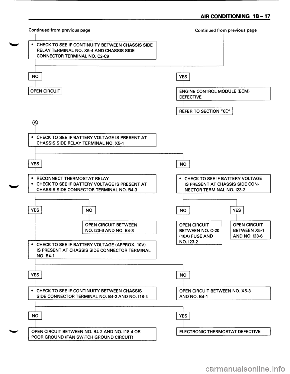
Continued from previous page
~ • CHECK TO SEE IF CONTINUITY BETWEEN CHASSIS SIDE
RELAY TERMINAL NO. X5-4 AND CHASSIS SIDE
CONNECTOR
TERMINAL NO. C2-C9
• CHECK TO SEE IF BATTERY VOLTAGE IS PRESENT AT
CHASSIS SIDE RELAY TERMINAL NO. XS-1
•
RECONNECT THERMOSTAT RELAY
• CHECK TO SEE IF BATTERY VOLTAGE IS PRESENT AT
CHASSIS SIDE CONNECTOR TERMINAL NO. B4-3
OPEN CIRCUIT BETWEEN
NO. 123-6 AND NO. B4-3
• CHECK TO SEE IF BATTERY VOLTAGE (APPROX. 10V)
IS PRESENT
AT CHASSIS SIDE CONNECTOR TERMINAL
NO. B4-1
• CHECK TO SEE IF CONTINUITY BETWEEN CHASSIS
SIDE CONNECTOR
TERMINAL NO. B4-2 AND NO. 118-4
OPEN CIRCUIT BETWEEN NO. B4-2 AND NO. 118-4 OR
POOR GROUND (FAN SWITCH GROUND CIRCUIT)
AIR CONDITIONING 18-17
Continued from previous page
• CHECK TO SEE IF BATTERY VOLTAGE
IS PRESENT
AT CHASSIS SIDE CON
NECTOR TERMINAL NO.
123-2
OPEN CIRCUIT
BETWEEN NO. C-20
(10A) FUSE
AND
NO. 123-2
AND NO. B4-1
OPEN CIRCUIT
BETWEEN XS-1
AND NO. 123-6
ELECTRONIC THERMOSTAT DEFECTIVE