display ISUZU TROOPER 1995 Workshop Manual
[x] Cancel search | Manufacturer: ISUZU, Model Year: 1995, Model line: TROOPER, Model: ISUZU TROOPER 1995Pages: 1928
Page 981 of 1928
AUTOMATIC TRANSMISSION (4L30-E) 7A-109
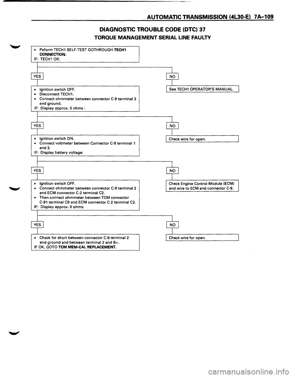
DIAGNOSTIC
TROUBLE CODE (DTC) 37
TORQUE MANAGEMENT SERIAL LINE FAULTY
• Peform TECH1 SELF-TEST GOTHROUGH TECH1 CONNECTION. IF: TECH1 OK:
• Ignition switch OFF. • Disconnect TECH1.
• Connect ohmmeter between connector C-9 terminal 3
and ground.
IF: Display approx. 0 ohms :
• Ignition switch ON.
• Connect voltmeter between Connector C-9 terminal 1
and 3.
IF: Display battery voltage:
• Ignition switch OFF. • Connect ohmmeter between connector C-9 terminal2 and ECM connector C-2 terminal C2. • Then connect ohmmeter between TCM connector C-91 terminal CB and ECM connector C-2 terminal C2. IF: Display approx. 0 ohms:
• Check for short between connector C-9 terminal 2
and ground and between terminal 2 and B+. IF OK, GOTO TCM MEM·CAL REPLACEMENT.
See TECH1 OPERATOR'S MANUAL
Check wire for open.
Check Engine Control
Module (ECM)
and wire
to ECM and connector C-9.
Page 995 of 1928
AUTOMATIC TRANSMISSION (4L30-E) 7A-123
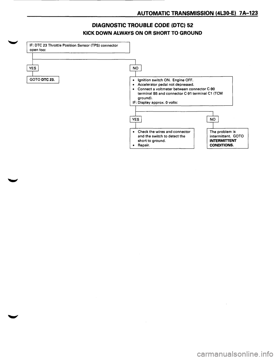
DIAGNOSTIC TROUBLE CODE (DTC) 52
KICK DOWN ALWAYS ON OR SHORT TO GROUND
IF: DTC 23 Throttle Position Sensor (TPS) connector
• Ignition switch ON. Engine OFF.
• Accelerator pedal not depressed. • Connect a voltmeter between connector C-90
terminal B5 and connector C-91 terminal C1 (TCM
ground).
IF: Display approx. 0 volts:
•
Check the wires and connector
and the switch to detect the
short to ground.
• Repair. The
problem is
intermittent. GOTO INTERMITTENT
CONDITIONS.
Page 997 of 1928
AUTOMATIC TRANSMISSION (4l30-E) 7 A-125
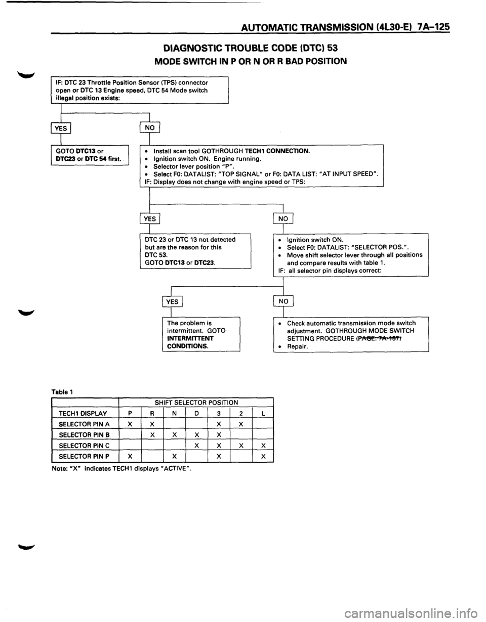
DIAGNOSTIC TROUBLE CODE (DTC) 53
MODE SWITCH IN P OR N OR R BAD POSITION
IF: DTC 23 Throttle Position Sensor (TPS) connector
open or DTC 13 Engine speed, DTC 54 Mode switch
illegal position exists:
Table 1
TECH1 DISPLAY p
SELECTOR PIN A X
SELECTOR PIN B
SELECTOR PIN C
SELECTOR PIN P X
• Install scan tool GOTHROUGH TECH1 CONNECTION.
• Ignition switch ON. Engine running.
• Selector lever position "P". • Select FO: DATALIST: "TOP SIGNAL" or FO: DATA LIST: "AT INPUT SPEED".
IF: Display does not change with engine speed or TPS:
DTC 23 or DTC 13 not detected
but are the reason for this DTC 53.
GOTO DTC13 or DTC23.
R
X
X
The problem is
intermittent. GOTO
INTERMITTENT
CONDITIONS.
SHIFT
SELECTOR POSITION
N D
3
X
X X X
X
X
X X
2 L
X
X X
X
• Ignition switch ON.
• Select FO: DATALIST: "SELECTOR POS.".
• Move shift selector lever through all positions
and compare
results with table 1. IF: all selector pin displays correct:
• Check automatic transmission mode switch
adjustment. GOTHROUGH MODE SWITCH
SETTING PROCEDURE (~. ;"A•1~'Yl
• Repair.
Note:
"X" indicatesTECH1 displays "ACTIVE".
Page 999 of 1928
AUTOMATIC TRANSMISSION (4L30-E) 7A-127
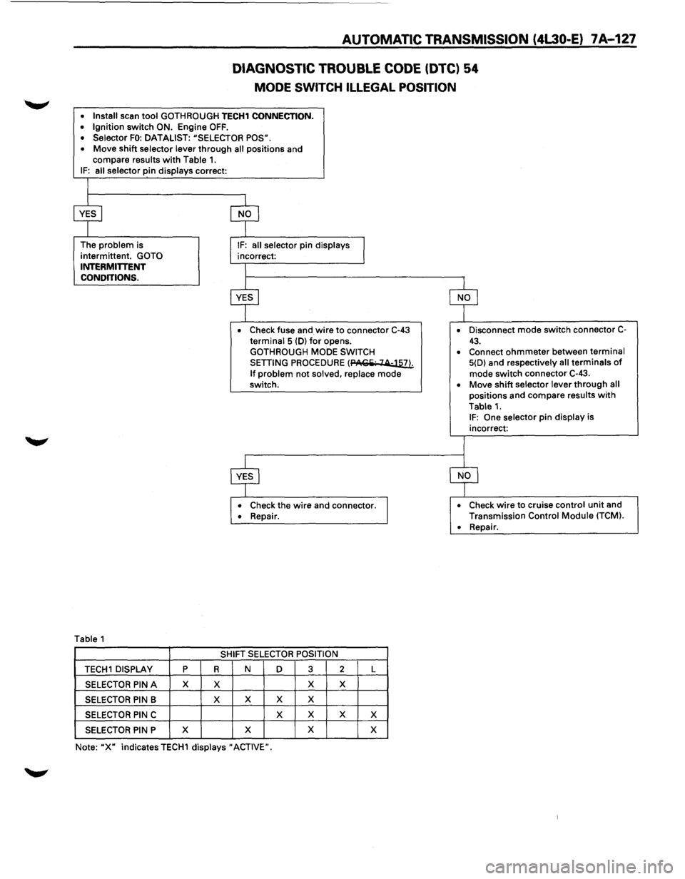
DIAGNOSTIC TROUBLE CODE (DTC) 54
MODE SWITCH ILLEGAL POSITION
• Install scan tool GOTH ROUGH TECH1 CONNECTION. • Ignition switch ON. Engine OFF. • Selector FO: DATALIST: "SELECTOR POS".
• Move shift selector lever through all positions and
compare results with Table 1. IF: all selector pin displays correct:
The
problem is
intermittent.
GOTO INTERMITTENT
CONDITIONS.
Table 1
• Check fuse and wire to connector C-43 terminal 5 (D) for opens.
GOTHROUGH MODE SWITCH
SETTING PROCEDURE (PACiii· 14-llli
If problem not solved, replace mode
switch.
• Check the wire and connector. • Repair.
SHIFT SELECTOR POSITION
TECH 1 DISPLAY p R N D 3 2 L
SELECTOR PIN A X X X X
SELECTOR PIN B X
X X X
SELECTOR PIN C X
X X X
SELECTOR PIN P X
X X
X
Note: "X" indicates TECH1 displays" ACTIVE". •
Disconnect
mode switch connector C-
43. • Connect ohmmeter between terminal 5(D) and respectively all terminals of mode switch connector C-43.
• Move shift selector lever through all positions and compare results with
Table 1. IF: One selector pin display is
incorrect:
• Check wire to cruise control unit and
Transmission Control Module (TCM).
•
Repair.
Page 1001 of 1928
AUTOMATIC TRANSMISSION (4L30-E) 7A-129
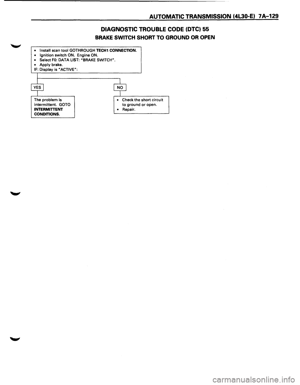
DIAGNOSTIC TROUBLE CODE (DTC) 55
BRAKE SWITCH SHORT TO GROUND OR OPEN
• Install scan tool GOTHROUGH TECH1 CONNECTION.
• Ignition switch ON. Engine ON.
• Select FO: DATA LIST: uBRAKE SWITCW.
•
Apply brake. IF: Display is uACTIVE":
The problem is
intermittent.
GOTO
INTERMITTENT
CONDITIONS. •
Check the short circuit to ground or open.
• Repair.
Page 1003 of 1928
AUTOMATIC TRANSMISSION (4L30-E) 7A-131
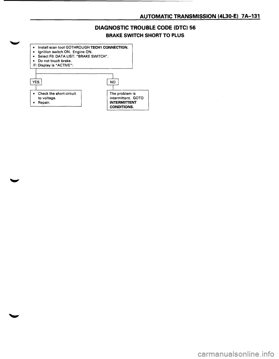
DIAGNOSTIC TROUBLE CODE (DTC) 56
BRAKE SWITCH SHORT TO PLUS
• Install scan tool GOTH ROUGH TECH1 CONNECTION.
• Ignition switch ON. Engine ON.
• Select FO: DATA LIST: uBRAKE SWITCH".
•
Do not touch brake. IF: Display is uACTIVEu:
•
Check the short circuit
to voltage.
•
Repair. The
problem is
intermittent. GOTO
INTERMITTENT CONDITIONS.
Page 1007 of 1928
AUTOMATIC TRANSMISSION (4l30-E) 7 A .... 135
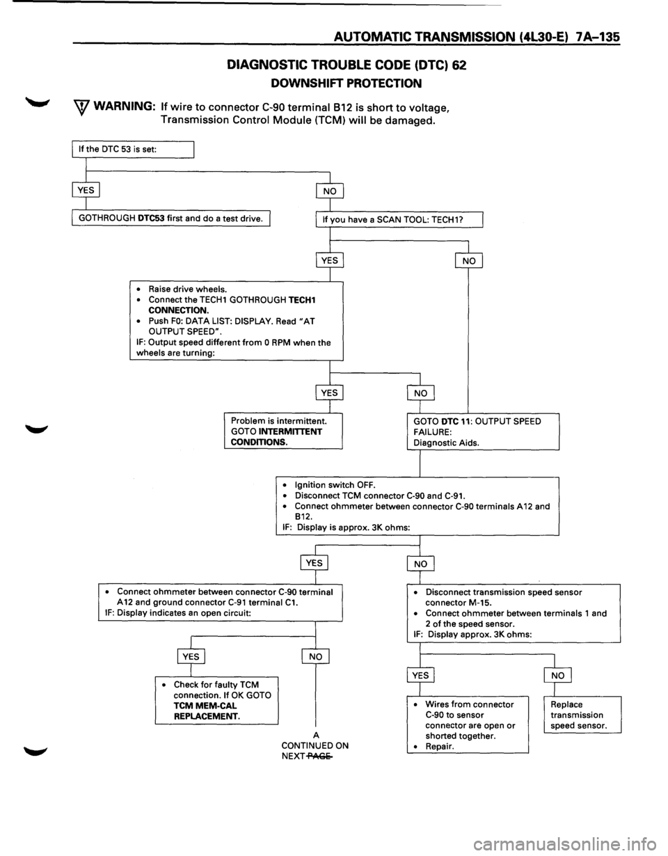
DIAGNOSTIC TROUBLE CODE (DTC) 62
DOWNSHIFT PROTECTION
W WARNING: If wire to connector C-90 terminal 812 is short to voltage,
Transmission Control Module (TCM) will be damaged.
GOTH ROUGH DTC53 first and do a test drive.
• Raise drive wheels.
•
Connect the TECH1 GOTHROUGH TECH1 CONNECTION.
•
Push FO: DATA LIST: DISPLAY. Read "AT OUTPUT SPEED".
IF: Output speed different from 0 RPM when the wheels are turning:
Problem is intermittent. GOTO INTERMITTENT
CONDITIONS.
•
Ignition switch OFF.
GOTO DTC 11: OUTPUT SPEED
FAILURE: Diagnostic Aids.
• Disconnect TCM connector C·90 and C-91. • Connect ohmmeter between connector C-90 terminals A 12 and
812.
IF: Display is approx. 3K ohms:
• Connect ohmmeter between connector C-90 terminal A12 and ground connector C-91 terminal C1. • Disconnect transmission speed sensor
connector M-15.
IF: Display indicates an open circuit:
• Check for faulty TCM
connection. If OK GOTO TCMMEM-CAL REPLACEMENT.
A
CONTINUED ON
NEXT-PAGe- •
Connect ohmmeter between terminals 1
and
2 of the speed sensor. IF: Display approx. 3K ohms:
• Wires from connector C-90 to sensor
connector are open or shorted together. • Repair.
Replace transmission
speed sensor.
Page 1008 of 1928
7A-136 AUTOMATIC TRANSMISSION (4l30-E)
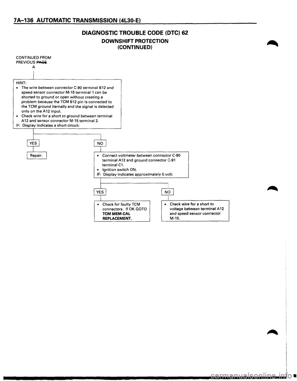
DIAGNOSTIC TROUBLE CODE (DTC) 62
DOWNSHIFT PROTECTION
(CONTINUED)
CONTINUED FROM
PREVIOUS PA(;Ii
A
HINT:
•
The wire between connector C-90 terminal 812 and
speed sensor connector M-15 terminal 1 can be
shorted
to ground or open without creating a problem because the TCM 812 pin is connected to the TCM ground iternally and the signal is detected only on the A 12 input. • Check wire for a short to ground between terminal
A12 and sensor connector M-15 terminal 2. IF: Display indicates a short circuit:
• Connect voltmeter between connector C-90 terminal A 12 and ground connector C-91
terminal C1. • Ignition switch ON. IF: Display indicates approximately 0 volt:
• Check
for faulty TCM connectors. If OK GOTO TCMMEM-CAL REPLACEMENT.
• Check wire for a short to voltage between terminal A12
and speed sensor connector
M-15.
•
Page 1015 of 1928
AUTOMATIC TRANSMISSION (4L30-E) 7A-143
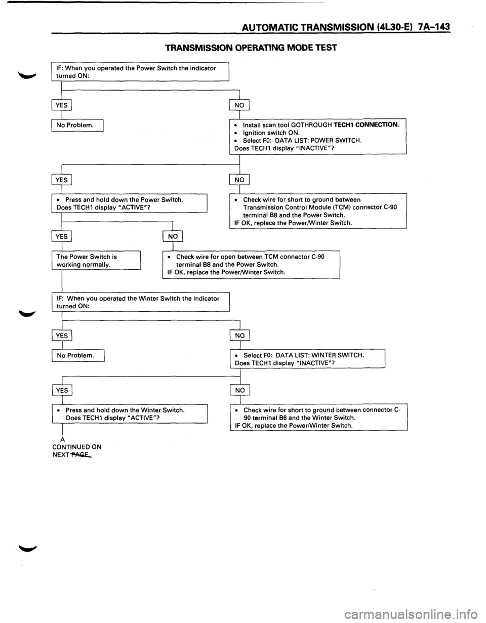
TRANSMISSION OPERATING MODE TEST
IF: When you operated the Power Switch the indicator
turned ON:
•
Press and hold down the Power Switch.
Does TECH1 display "ACTIVE"? •
Install
scan tool GOTHROUGH TECH1 CONNECTION.
• Ignition switch ON.
• Select FO: DATA LIST: POWER SWITCH.
Does TECH1 display "INACTIVE"?
•
Check wire for short to ground between
Transmission Control Module (TCM) connector C-90
terminal
88 and the Power Switch.
IF OK, replace the Power/Winter Switch.
working
normally. •
Check wire for open
between TCM connector C-90
terminal 88 and the Power Switch. IF OK, replace the Power/Winter Switch.
IF: When you operated the Winter Switch the indicator
turned ON:
•
Press and hold down the Winter Switch.
Does TECH1 display "ACTIVE"?
A CONTINUED ON
NEXT~
DATA LIST: WINTER SWITCH.
•
Check wire for short to ground between connector C-90 terminal 86 and the Winter Switch. IF OK, replace the Power/Winter Switch.
Page 1017 of 1928
AUTOMATIC TRANSMISSION (4L30-E) 7 A-145
TCM PRECAUTONS
The TCM can be damaged by:
(1) The Electrostatic discharge
(2) The short circuit of some terminals to voltage
or to ground.
Electrostatic Discharge Damage Description:
(1) Electronic components used to control systems
are often designed
to carry very low voltage,
and are
very susceptible to damage caused by
electrostatic discharge. It is possible for less
than 100 volts of static electricity to cause
damage
to some electronic components. By
comparison,
it takes as much as 4000 volts for
a person to even feel the zap of a static
discharge.
(2) There are several
ways for a person to become
statically charged. The most common methods
of charging are by friction and induction. An
example
of charging by friction is a person
sliding across a car seat, in
which a charge of
as much as 25,000 volts can build up.
Charging
by induction occurs when a person
with well insulated shoes stands near a highly
charged object and momentarily touches
ground. Charges for the same polarity are
drained off, leaving the person
highly charged
with the opposite polarity. Static charges of
either type can cause damage, therefore, it is
important to use care when handling and
testing electronic components.
NOTICE: To prevent possible Electrostatic
Discharge damage:
(1) Do not touch the TCM connector pins or
soldered components on the TCM circuit
board.
(2) When handling a Mem-Cal (PROM), do not
touch the component leads, and do not
remove integrated circuit from carrier.
(3) Be sure to follow the guidelines listed below if
servicing any of these electronic components:
(4) Do not open the replacement part package
until
it is time to install the part.
(5)
Avoid touching electrical terminals of the part.
(6) Before removing the part from its package,
ground the package to a known good ground
on the vehicle.
(7) Always touch a known good ground before
handling the part. This step should be repeated
before installing
the part if the part has been
handled
while sliding across the seat, while
sitting down from a standing position or while
walking some distance.
INFORMATION ON TCM:
(1) The Transmission Control Module (TCM) is
located in the
driver compartment and is the
control center
of the electronic transmission
control system.
(2) The TCM must be maintained at a temperature
below 185°F (85°C) at all times. This is most
essential if the vehicle is put through a paint
baking process. The
TCM will become in
operative
if its temperature exceeds 85°C
(185°F). Therefore, it is recommended that the
TCM be removed or that temporary insulation
be placed around the
TCM during the time the
vehicle is in a paint oven
or other high
temperature process.
(3) The
TCM is designed to process the various
inputs and then respond by sending the
appropriate electrical signals
to control trans
mission upshift,
downshift, shift feel and
torque converter clutch engagement.
(4) The TCM constantly interprets information
from the various sensors, and controls the
systems
that affect transmission and vehicle
performance. By analyzing operational prob
lems, the
TCM is able to perform a diagnostic
function
by displaying DTC(s) and aid the
technician in making repairs.
PROM/MEM-CAL:
(1) Information for a specific engine and vehicle is
programmed using an integrated circuit called
a Programmable Read-Only
Memory (PROM).
It
is also called a MEM-CAL (Memory Cali
brator). This allows one model of controller to
be used for many different vehicles. The
PROM is located inside the TCM and has
information on the engine, transmission,
calibration., etc. While one
TCM part number
can be used by many vehicle lines, a PROM is
more specific and must be used only with the
right vehicles. For this reason, it is very
important to check the latest parts book and
Service Bulletin
information for the correct part
number when replacing a PROM.