display ISUZU TROOPER 1995 Workshop Manual
[x] Cancel search | Manufacturer: ISUZU, Model Year: 1995, Model line: TROOPER, Model: ISUZU TROOPER 1995Pages: 1928
Page 1018 of 1928
7A-146 AUTOMATIC TRANSMISSION (4L30-E)
INTERMITTENT CONDITIONS
If the TECH1 displays a diagnostic trouble code as
intermittent, or if after a test drive a DTC does not
reappear though the detection conditions for this
DTC are present: the problem is most likely a faulty
electrical connection or loose wiring. Terminals
and
grounds should always be the prime suspect.
lntermittents rarely occur inside sophisticated
electronic components such
as the TCM.
Use the
DTC information to understand which wires
and sensors are involved.
When an
intermittent problem is encountered,
check suspect circuits for:
(1) Poor terminal to wire connection.
(2) Terminals not fully seated in the connector
body (backed out).
(3) Improperly formed or damaged terminals.
(4) Loose, dirty, or corroded ground connections:
HINT: Any time you have an intermittent in
more than one circuit, check whether the circuits
share a
common ground connection.
(5) Pinched or damaged wires.
(6) Electro-Magnetic Interference (EMI):
HINT:
Check that all wires are properly routed
away from spark plug wires, distributor wires,
coil, and generator. Also check
for improperly
installed electrical options, such as lights, 2-way
radios, etc. Use
the
F3: SNAPSHOT mode of the TECH 1 to help
isolate the cause
of an intermittent fault. The
snapshot
mode will record information before and
after the problem occurs. Set the snapshot
to
"trigger" on the suspect DTC or, if you notice the
reported
symptom during test drive, trigger the
snapshot
manually.
(1) NOTE: When TECH1 is plugged the shifts are
always
done at the maximum pressure. This
means
that if you do SNAPSHOT while driving
you will! notice firm shifts.
After the snapshot has been triggered, command
the TECH1 to play back the flow of data recorded
from each of the various sensors. Signs of an
intermittent fault in a sensor circuit are sudden
unexplainable jump in data values out of the
normal range.
CASE:
problem still not solved GOTO TCM MEM
CAL REPLACEMENT.
•
Page 1508 of 1928
8-318 CHASSIS ELECTRICAL
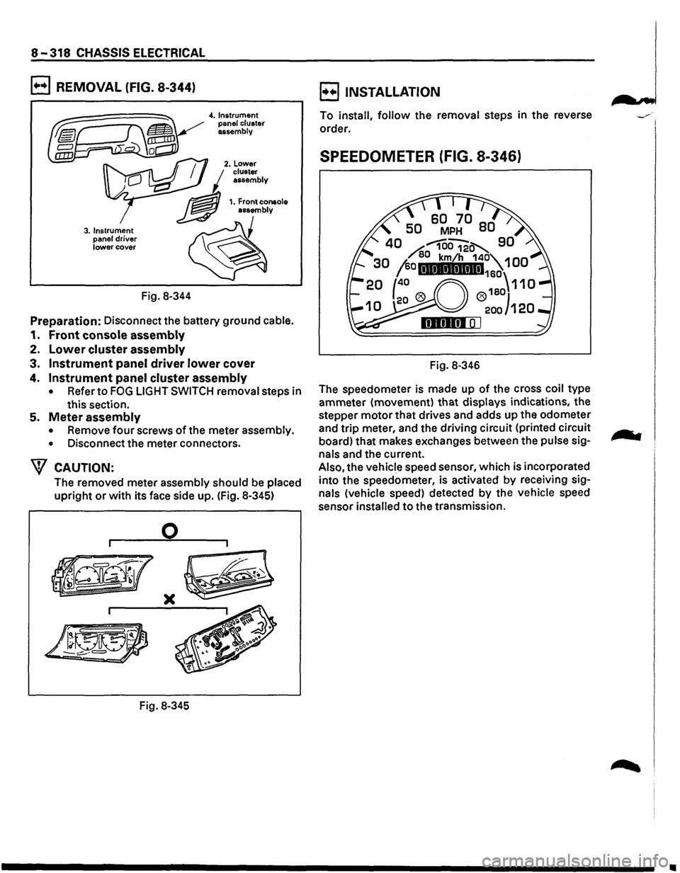
B REMOVAL (FIG. 8-344)
3. Instrument
panel driver lower cover
Fig. 8-344
4. Instrument
panel cluster
assembly
Preparation: Disconnect the battery ground cable.
1. Front console assembly
2. Lower cluster assembly
3. Instrument panel driver lower cover
4. Instrument panel cluster assembly
• Refer to FOG LIGHT SWITCH removal steps in
this section.
5. Meter assembly
• Remove four screws of the meter assembly.
•
Disconnect the meter connectors.
W CAUTION:
The removed meter assembly should be placed
upright or with its face side up. (Fig. 8-345)
0
)(
Fig. 8-345
B INSTALLATION
To install, follow the removal steps in the reverse
order.
SPEEDOMETER (FIG. 8-346)
Fig. 8-346
The speedometer is made up
of the cross coil type
ammeter (movement)
that displays indications, the
stepper
motor that drives and adds up the odometer
and
trip meter, and the driving circuit (printed circuit
board) that makes exchanges between the
pulse sig
nals and the current.
Also, the vehicle speed sensor, which is incorporated
into the speedometer, is activated
by receiving sig
nals (vehicle speed) detected by the vehicle speed
sensor
installed to the transmission.
•
Page 1509 of 1928
![ISUZU TROOPER 1995 Workshop Manual (1!] ON-VEHICLE SERVICE
"-"" Check the meter display accuracy and the operation
of the odometer with the speedometer tester.
\f CAUTION:
Inappropriate tire inflation may affect the accu
rac](/img/61/57183/w960_57183-1508.png "ISUZU TROOPER 1995 Workshop Manual (1!] ON-VEHICLE SERVICE
\"-\"\" Check the meter display accuracy and the operation
of the odometer with the speedometer tester.
\f CAUTION:
Inappropriate tire inflation may affect the accu
rac")
(1!] ON-VEHICLE SERVICE
"-"" Check the meter display accuracy and the operation
of the odometer with the speedometer tester.
\f CAUTION:
Inappropriate tire inflation may affect the accu
racy
of the odometer.
(To
conductthis test, refer to the tester manufac
turer's instruction manual.)
IGN GND
SEN
CHASSIS ELECTRICAL 8-319
(MPH)
Tester display speed Meter
display permissible
level
20 18.3-21.7
40 38.3-41.7
60 58.3-61.7
80 78.8-82.8
100 98.8-102.8
120 118.5-123.1
NOTE: Since the meter display permissible levels
above are specifications solely
for the
meter,
they are to be used as reference
values when conducting on-vehicle service.
~ INDIVIDUAL INSPECTION
I t!!.l Remove the speedometer from the meter
assembly and measure the resistance and the
current consumption between each terminal.
(Fig. 8-347)
Replace the speedometer
when the result of
inspection is found abnormal.
Resistance value
Red(+) Black(-) Black(-) Red(+)
IGN GND IGN GND IGN-GND 00 30.6-37.4k
SEN GND SEN GND SEN-GND 28.8-35.2k 00
4P GND 4P GND 4P-GND 13.5 -16.5k 00
Note: Use the
analog type circuit tester (range: x 1k)
Current value
Terminal
symbol
IGN-GND
~ 8
Current
consumption
85 ± 15mA Remarks
(when
12 ± 1V No signal input
applied)
Note: 1. Use the analog type circuit tester.
2. Since the current consumption fluctuates
when the source voltage varies, check
to
be sure that the voltage applied is 12V ± 1 V.
Fig. 8-347
Page 1511 of 1928
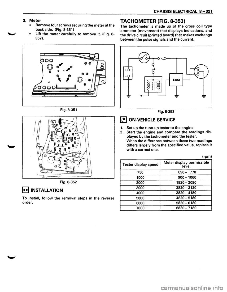
3. Meter
• Remove four screws securing the meter at the
back side. (Fig.
8-351)
• Lift the meter carefully to remove it. (Fig. 8-
352).
0
q;J"' 0
0 0 0,
0 0
0 I
Fig. 8-351
Fig. 8-352
E) INSTALLATION
00
0
To install, follow the removal steps in the reverse
order.
CHASSIS ELECTRICAL 8-321
TACHOMETER (FIG. 8-353)
The tachometer is made up of the cross coil type
ammeter (movement) that displays indications, and
the drive circuit (printed board)
that makes exchange
between the
pulse signals and the current.
Fig.
8-353
(1!1 ON-VEHICLE SERVICE
1. Set up the tune-up tester to the engine.
2. Start the engine and compare the readings dis
played by the tachometer and the tester.
When the difference between these
two readings
differs
largely from the specified value, replace it
with a correct one.
(rpm)
Tester
display speed Meter
display permissible level
750 690-770
1000
900-1060
2000 1820-2090
3000 2820-3120
4000 3820-4180
5000 4820-5180
6000 5820-6180
7000 6820-7180
Page 1512 of 1928
8 -322 CHASSIS ELECTRICAL
NOTE: Since
the meter display permissible lev
els
above are specifications solely for
the meter, they are to be used as refer
ence values when conducting on-vehicle
inspection.
p
IGN GND
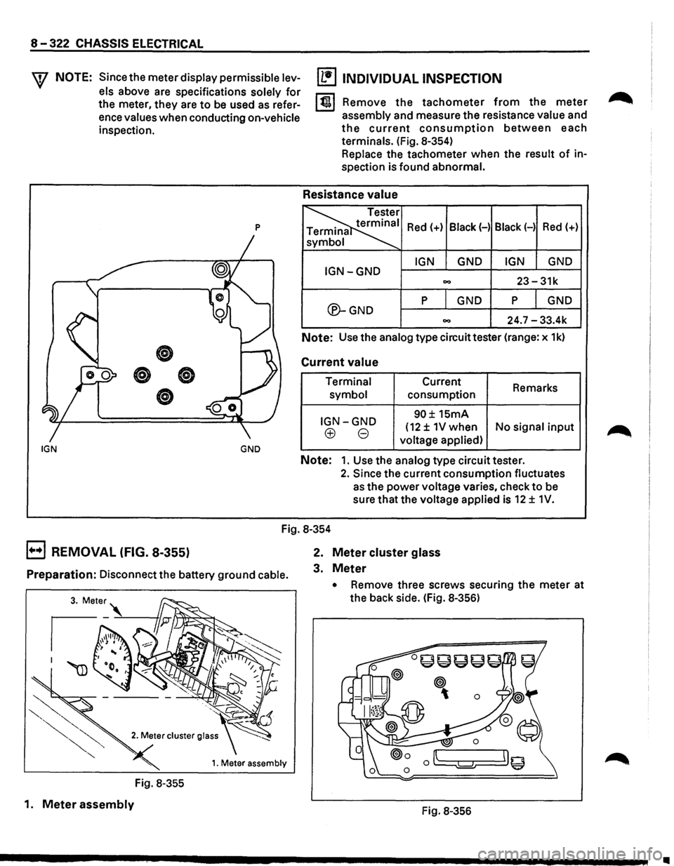
[b!J INDIVIDUAL INSPECTION
I tii~,l Remove the tachometer from the meter
assembly and measure the resistance value and
the current consumption between each
terminals. (Fig. 8-354)
Replace the tachometer when the result of in
spection is found abnormal.
Resistance value
Red(+) Black(-) Black(-) Red(+)
IGN GND IGN GND IGN-GND 00 23-31k
®-GND
p GND p GND
00 24.7 -33.4k
Note: Use the analog type
circuittester (range: x 1k)
Current value
Terminal
symbol
IGN-GND
(±) 8
Current
consumption
90± 15mA Remarks
(12 ± 1V when
No signal input
voltage applied)
Note: 1. Use the analog type circuit tester.
2. Since the current consumption fluctuates
as the power voltage varies, check to be
sure that the
voltage applied is 12 ± 1V.
Fig. 8-354
E) REMOVAL (FIG. 8-355)
Preparation: Disconnect the battery ground cable.
1. Meter assembly
Fig. 8-355
1.
Meter assembly
2. Meter cluster glass
3. Meter
• Remove three screws securing the meter at
the back side. (Fig. 8-356)
Fig. 8-356
•
Page 1602 of 1928
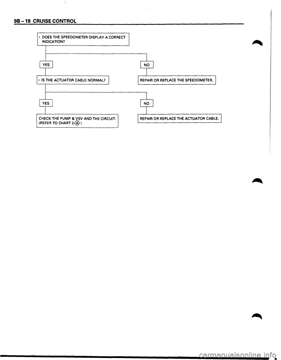
98 -18 CRUISE CONTROL
• DOES THE SPEEDOMETER DISPLAY A CORRECT I INDICATION?
l
I YES I l NO I
I
• IS THE ACTUATOR CABLE NORMAL? I l REPAIR OR REPLACE THE SPEEDOMETER. I
I YES I
$
CHECK THE PUMP & VSV AND THE CIRCUIT J I REFER TO CHART 2@) I REPAIR OR REPLACE THE ACTUATOR CABLE. J
Page 1610 of 1928
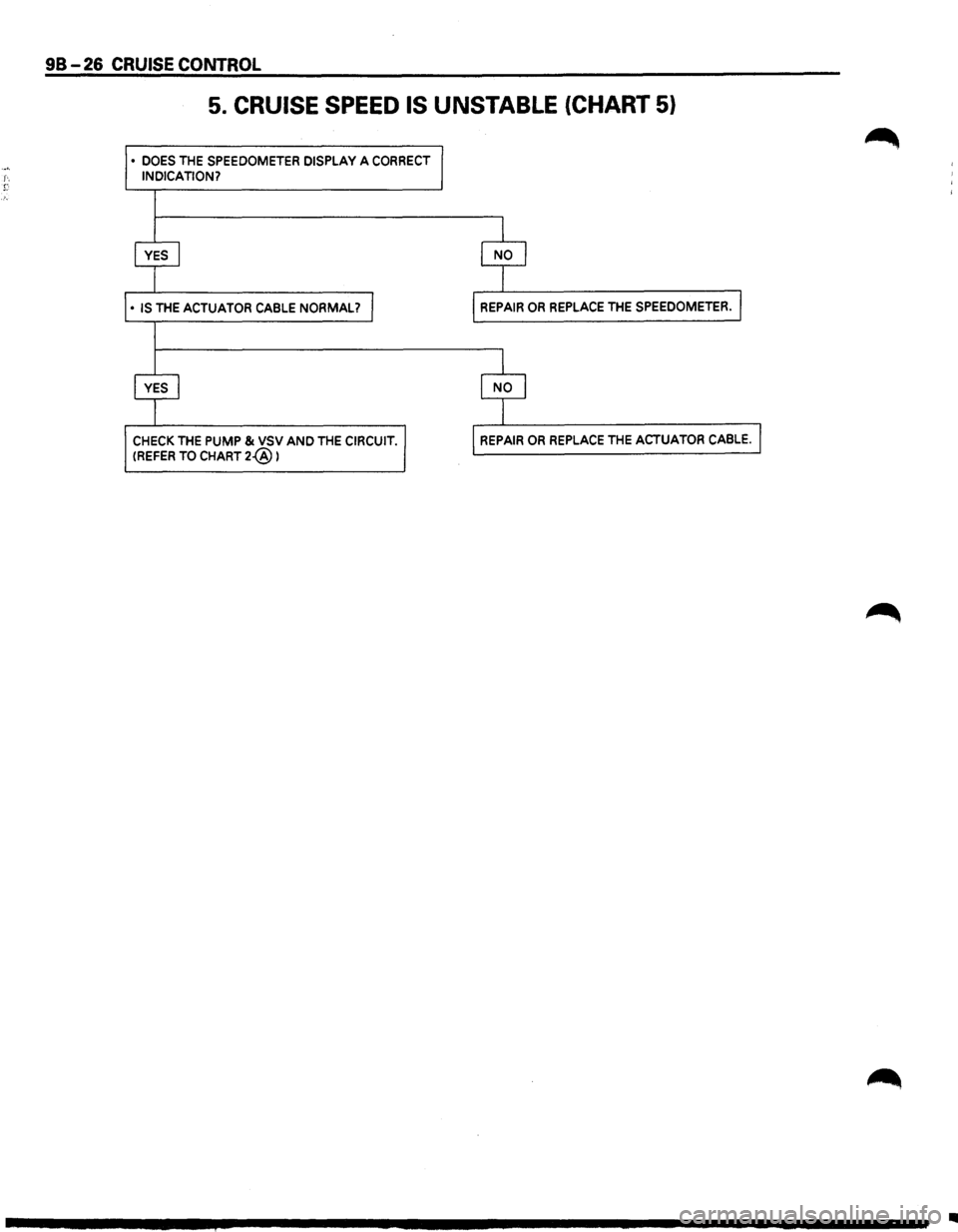
...... f-. r:
98-26 CRUISE CONTROL
5. CRUISE SPEED IS UNSTABLE (CHART 5)
• DOES THE SPEEDOMETER DISPLAY A CORRECT INDICATION?
CHECK THE PUMP & VSV AND THE CIRCUIT. (REFER TO CHART 2-@ )
..
Page 1657 of 1928
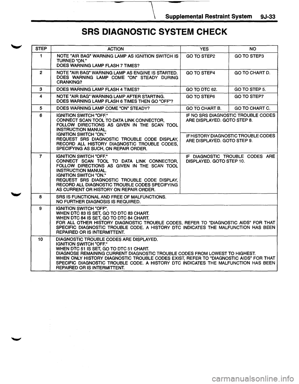
Supplemental Restraint System 9J-33
SRS DIAGNOSTIC SYSTEM CHECK
STEP
ACTION YES NO
1 NOTE "AIR BAG" WARNING LAMP AS IGNITION SWITCH IS GOTOSTEP2 GOTOSTEP3 TURNED "ON."
DOES WARNING
LAMP FLASH 7 TIMES?
2 NOTE "AIR BAG" WARNING LAMP AS ENGINE IS STARTED. GOTOSTEP4 GO TO CHART D. DOES WARNING LAMP COME "ON" STEADY DURING
CRANKING?
3 DOES WARNING LAMP FLASH 4 TIMES? GOTO DTC62. GO TO STEPS.
4 NOTE "AIR BAG" WARNING LAMP AFTER STARTING. GOTOSTEP6 GOTOSTEP7 DOES WARNING LAMP FLASH 6 TIMES THEN GO "OFF"?
5 DOES WARNING LAMP COME "ON" STEADY? GO TO CHART B. GO TO CHART C.
6 IGNITION SWITCH "OFF." IF
NO SRS DIAGNOSTIC TROUBLE CODES
CONNECT SCAN TOOL TO
DATA LINK CONNECTOR, ARE DISPLAYED. GOTO STEP 8. FOLLOW DIRECTIONS AS GIVEN IN THE SCAN TOOL
INSTRUCTION MANUAL.
IGNITION SWITCH "ON."
IF HISTORY DIAGNOSTIC TROUBLE CODES
REQUEST SRS DIAGNOSTIC TROUBLE CODE DISPLAY, ARE DISPLAYED. GOTO STEP 9. RECORD ALL HISTORY DIAGNOSTIC TROUBLE CODES,
SPECIFYING AS SUCH, ON REPAIR ORDER.
7 IGNITION SWITCH "OFF." IF DIAGNOSTIC TROUBLE CODES ARE
CONNECT SCAN TOOL TO DATA LINK CONNECTOR, DISPLAYED. GOTO STEP 10. FOLLOW DIRECTIONS AS GIVEN IN THE SCAN TOOL
INSTRUCTION MANUAL. IGNITION SWITCH "ON."
REQUEST SRS DIAGNOSTIC
TROUBLE CODE DISPLAY, RECORD ALL DIAGNOSTIC TROUBLE CODES SPECIFYING
AS CURRENT OR HISTORY ON REPAIR ORDER.
8
SRS IS FUNCTIONAL AND FREE OF MALFUNCTIONS.
NO FURTHER DIAGNOSIS IS REQUIRED.
9 IGNITION SWITCH "OFP'. WHEN DTC 83 IS SET, GO TO DTC 83 CHART. WHEN DTC 84 IS SET, GO TO DTC 84 CHART. FOR ALL OTHER HISTORY DIAGNOSTIC TROUBLE CODES, REFER TO "DIAGNOSTIC AIDS" FOR THAT
SPECIFIC DIAGNOSTIC TROUBLE CODE. A HISTORY DTC INDICATES THE MALFUNCTION HAS BEEN REPAIRED OR IS INTERMITTENT.
10 DIAGNOSTIC
TROUBLE CODES ARE DISPLAYED.
IGNITION SWITCH "OFF."
WHEN DTC 51 IS SET, GO TO DTC 51 CHART. DIAGNOSE REMAINING CURRENT DIAGNOSTIC TROUBLE CODES FROM LOWEST TO HIGHEST. WHEN ONLY HISTORY DIAGNOSTIC TROUBLE CODES EXIST, REFER TO "DIAGNOSTIC AIDS" FOR THAT SPECIFIC DIAGNOSTIC TROUBLE CODE. A HISTORY DTC INDICATES THE MALFUNCTION
HAS BEEN
REPAIRED OR IS INTERMITTENT.
Page 1659 of 1928
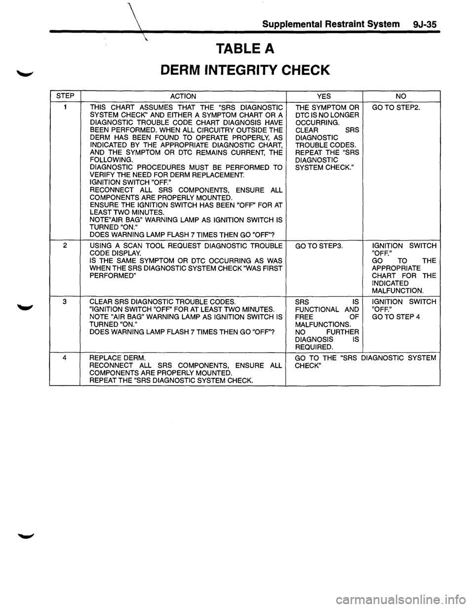
STEP
2
3
Supplemental Restraint System 9J-35
TABLE A
DERM INTEGRITY CHECK
ACTION
THIS
CHART ASSUMES THAT THE "SRS DIAGNOSTIC
SYSTEM CHECK" AND EITHER A SYMPTOM CHART OR A
DIAGNOSTIC TROUBLE CODE CHART DIAGNOSIS HAVE BEEN PERFORMED. WHEN ALL CIRCUITRY OUTSIDE THE
DERM HAS BEEN FOUND TO OPERATE PROPERLY, AS
INDICATED BY THE APPROPRIATE DIAGNOSTIC CHART, AND THE SYMPTOM OR DTC REMAINS CURRENT, THE FOLLOWING.
DIAGNOSTIC PROCEDURES MUST BE PERFORMED TO VERIFY THE NEED FOR DERM REPLACEMENT. IGNITION SWITCH "OFF."
RECONNECT
ALL SRS COMPONENTS, ENSURE ALL
COMPONENTS ARE PROPERLY MOUNTED.
ENSURE THE IGNITION SWITCH HAS BEEN "OFP' FOR AT LEAST TWO MINUTES.
NOTE"AIR BAG" WARNING LAMP AS IGNITION SWITCH IS TURNED "ON."
DOES WARNING LAMP FLASH 7 TIMES THEN GO "OFF"?
USING
A SCAN TOOL REQUEST DIAGNOSTIC TROUBLE CODE DISPLAY. IS THE SAME SYMPTOM OR DTC OCCURRING AS WAS WHEN THE SRS DIAGNOSTIC SYSTEM CHECK "WAS FIRST
PERFORMED"
CLEAR SRS DIAGNOSTIC TROUBLE CODES.
"IGNITION SWITCH "OFP' FOR AT LEAST TWO MINUTES.
NOTE "AIR BAG" WARNING LAMP AS IGNITION SWITCH IS TURNED "ON."
DOES WARNING LAMP FLASH 7 TIMES THEN GO "OFF"? YES
THE SYMPTOM OR DTC IS NO LONGER
OCCURRING. CLEAR SRS
DIAGNOSTIC
TROUBLE CODES. REPEAT THE "SRS
DIAGNOSTIC SYSTEM CHECK."
GOTOSTEP3.
SRS IS
FUNCTIONAL AND
FREE OF
MALFUNCTIONS.
NO FURTHER DIAGNOSIS IS REQUIRED. NO
GOTO STEP2.
IGNITION
SWITCH
"OFF." GO
TO THE APPROPRIATE CHART FOR THE INDICATED MALFUNCTION.
IGNITION SWITCH
"OFF."
GOTO STEP4
4 REPLACE DERM. GO TO THE "SRS DIAGNOSTIC SYSTEM
RECONNECT ALL SRS COMPONENTS, ENSURE ALL CHECK"
COMPONENTS ARE PROPERLY MOUNTED.
REPEAT THE "SRS DIAGNOSTIC SYSTEM CHECK.
Page 1671 of 1928
Supplemental Restraint System 9J-47
DTC 16
PASSENGER INITIATOR CIRCUIT RESISTANCE LOW
STEP
ACTION YES NO
1 WAS THE "SRS
DIAGNOSTIC SYSTEM CHECK'' GOTOSTEP2. GO TO THE "SRS PERFORMED? DIAGNOSTIC
SYSTEM CHECK."
2
WHEN MEASUREMENTS ARE REQUESTED IN THIS CHART GOTOSTEP5. GOTOSTEP3. USE J-39200 DVM WITH CORRECT TERMINAL ADAPTER FROM J-35616-A. IS DTC 22 ALSO CURRENT?
3
IGNITION SWITCH "OFF." GOTOSTEP4. GOTOSTEP6. DISCONNECT DRIVER AND PASSENGER
INFLATOR
MODULES, YELLOW 2-WAY OR 4-WAY CONNECTORS
LOCATED AT THE TOP OF THE STEERING COLUMN AND
BEHIND THE
liP COMPARTMENT DOOR ASSEMBLY.
CONNECT J-41433 SRS DRIVER/PASSENGER LOAD TOOL
TO STEERING COLUMN HARNESS CONNECTOR AND PASSENGER INFLATOR MODULE HARNESS CONNECTOR.
IGNITION SWITCH "ON."
IS DTC
16 CURRENT?
4
IGNITION SWITCH "OFF." GO TO CHART A. GOTOSTEP7. DISCONNECT SRS DRIVER/PASSENGER LOAD TOOL.
DISCONNECT DERM. MEASURE RESISTANCE ON DERM HARNESS CONNECTOR
FROM TERMINAL "A7'' TO TERMINAL "B7".
DOES J-39200 DISPLAY "OL"(INFINITE)?
5 IGNITION SWITCH "OFF." GOTOSTEPB. DISCONNECT DRIVER AND PASSENGER INFLATOR
MODULES, YELLOW 2-WAY OR 4-WAY CONNECTORS
LOCATED
AT THE TOP OF THE STEERING COLUMN AND
BEHIND THE liP COMPARTMENT DOOR ASSEMBLY. REPLACE SRS HARNESS.
6 IGNITION SWITCH "OFF."
GO TO STEPS.
REPLACE PASSENGER INFLATOR MODULE.
7 REPLACE SRS HARNESS. GO TO STEPS.
8 RECONNECT ALL SRS COMPONENTS, ENSURE ALL GO TO THE "SRS DIAGNOSTIC SYSTEM
COMPONENTS ARE PROPERLY MOUNTED. CHECK". CLEAR SRS DIAGNOSTIC TROUBLE CODES. REPEAT THE "SRS DIAGNOSTIC SYSTEM CHECK."