display ISUZU TROOPER 1995 Repair Manual
[x] Cancel search | Manufacturer: ISUZU, Model Year: 1995, Model line: TROOPER, Model: ISUZU TROOPER 1995Pages: 1928
Page 823 of 1928
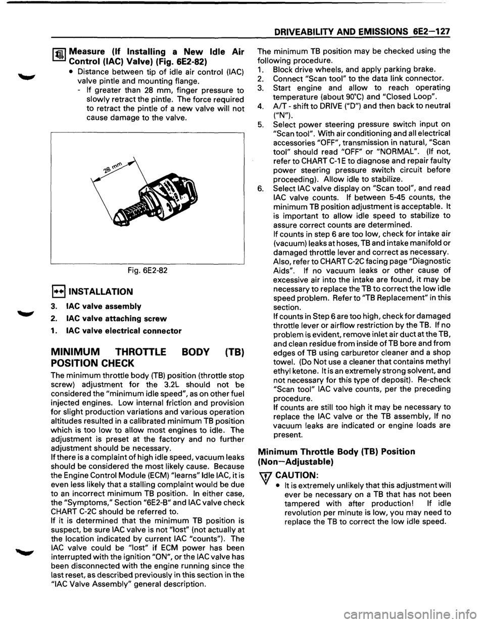
1~1 Measure (If Installing a New Idle Air
Control (lAC) Valve) (Fig. 6E2-82)
• Distance between tip of idle air control (lAC)
valve pintle and mounting flange.
-
If greater than 28 mm, finger pressure to
slowly retract the pintle. The force required
to retract the pintle
of a new valve will not
cause damage to the valve.
Fig. 6E2-82
E) INSTALLATION
3. lAC valve assembly
2. lAC valve attaching screw
1. lAC valve electrical connector
MINIMUM THROTTLE BODY (TB)
POSITION CHECK
The minimum throttle body (TB) position (throttle stop
screw) adjustment
for the 3.2L should not be
considered the
"minimum idle speed", as on other fuel
injected engines. Low internal friction and provision
for slight production variations and various operation
altitudes resulted in a calibrated
minimum TB position
which is too
low to allow most engines to idle. The
adjustment is preset at the factory and no further
adjustment should be necessary.
If there is a complaint of high idle speed, vacuum leaks
should be considered the
most likely cause. Because
the Engine
Control Module (ECM) "learns" Idle lAC, it is
even less likely
that a stalling complaint would be due
to
an incorrect minimum TB position. In either case,
the
"Symptoms," Section "6E2-B" and lAC valve check
CHART C-2C should be referred to.
If it is determined that the minimum TB position is
suspect,
be sure lAC valve is not "lost'' (not actually at
the location indicated by current
lAC "counts"). The
lAC valve could be "lost" if ECM power has been
interrupted
with the ignition "ON", or the lAC valve has
been disconnected
with the engine running since the
last reset,
as described previously in this section in the
"lAC Valve Assembly" general description.
DRIVEABILITY AND EMISSIONS 6E2-127
The minimum TB position may be checked using the
following procedure.
1. Block drive wheels, and apply parking brake.
2. Connect "Scan tool" to the data link connector.
3. Start engine and allow to reach operating
temperature (about
go•q and "Closed Loop".
4. A/T-shift to DRIVE ("D") and then back to neutral
("N").
5. Select power steering pressure switch input on
"Scan tool". With air conditioning and all electrical
accessories
"OFF", transmission in natural, "Scan
tool" should read "OFF" or "NORMAL". (If not,
refer to
CHART C-1 E to diagnose and repair faulty
power steering pressure switch circuit before
proceeding).
Allow idle to stabilize.
6. Select lAC valve display on "Scan tool", and read
lAC valve counts. If between 5-45 counts, the
minimum
TB position adjustment is acceptable. It
is important to allow idle speed to stabilize to
assure correct counts are determined.
If counts in step 6 are too low, check for intake air
(vacuum) leaks at hoses,
TB and intake manifold or
damaged throttle lever and correct as necessary.
Also, refer to
CHART C-2C facing page "Diagnostic
Aids". If no vacuum leaks or other cause of
excessive air into the intake are found, it may be
necessary
to replace the TB to correct the low idle
speed problem. Refer to
"TB Replacement" in this
section.
If counts in Step 6 are too high, check for damaged
throttle lever or airflow restriction by the
TB. If no
problem is evident, remove inlet air
duct at the TB,
and
clean residue from inside of TB bore and from
edges of TB using carburetor cleaner and a shop
towel. (Do Not use a cleaner that contains methyl
ethyl ketone.
It is an extremely strong solvent, and
not necessary for this type of deposit). Re-check
"Scan tool" lAC valve counts, per the preceding
procedure.
If counts are still too high it may be necessary to
replace the
lAC valve or the TB assembly, If no
vacuum leaks are indicated
or engine loads are
present.
Minimum Throttle Body (TB) Position
(Non-Adjustable)
\fl CAUTION:
VI • It is extremely unlikely that this adjustment will
ever be necessary on a TB that has not been
tampered
with after production! If idle
revolution per minute is low, you may need
to
replace the TB to correct the low idle speed.
Page 827 of 1928
DRIVEABILITY AND EMISSIONS 6E2-131
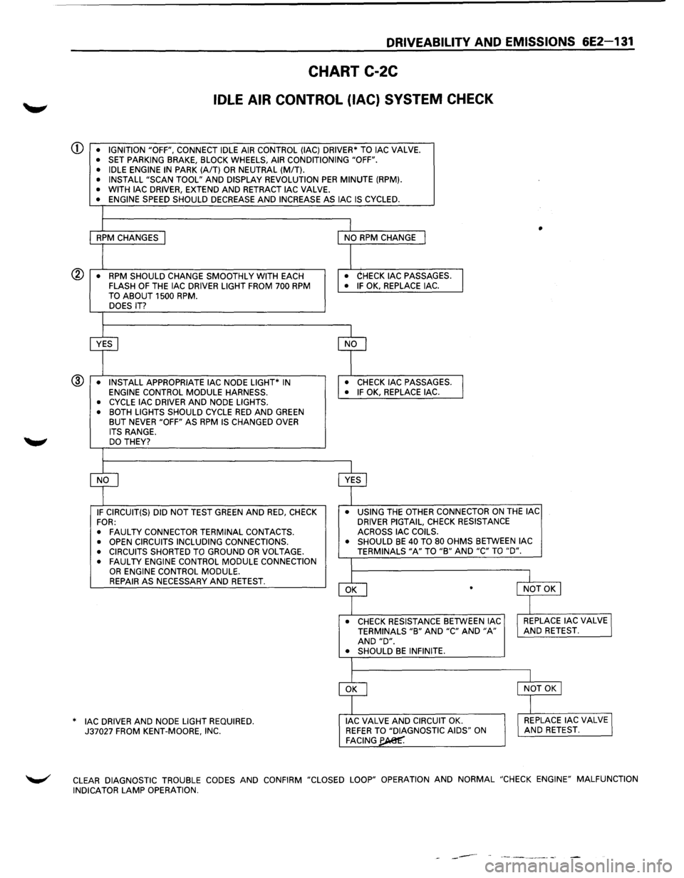
CHART C-2C
IDLE AIR CONTROL (lAC) SYSTEM CHECK
CD • IGNITION "OFF", CONNECT IDLE AIR CONTROL (lAC) DRIVER* TO lAC VALVE. • SET PARKING BRAKE, BLOCK WHEELS, AIR CONDITIONING "OFF".
• IDLE ENGINE IN PARK (A/T) OR NEUTRAL (MIT). • INSTALL "SCAN TOOL" AND DISPLAY REVOLUTION PER MINUTE (RPM). • WITH lAC DRIVER, EXTEND AND RETRACT lAC VALVE. • ENGINE SPEED SHOULD DECREASE AND INCREASE AS lAC IS CYCLED.
I
1 I • RPM CHANGES I NO RPM CHANGE I
I I • RPM SHOULD CHANGE SMOOTHLY
WITH EACH • CHECK lAC PASSAGES.
I FLASH OF THE lAC DRIVER LIGHT FROM 700 RPM • IF OK, REPLACE lAC.
TO ABOUT 1500 RPM. DOES IT?
I
~ cf
• INSTALL APPROPRIATE lAC NODE LIGHT* IN • CHECK lAC PASSAGES.
l ENGINE CONTROL MODULE HARNESS. • IF OK, REPLACE lAC. ®
• CYCLE lAC
DRIVER AND NODE LIGHTS.
• BOTH LIGHTS SHOULD CYCLE RED AND GREEN BUT NEVER "OFF" AS RPM IS CHANGED OVER
ITS RANGE. DO THEY?
I
cf ~ IF CIRCUIT(S) DID NOT TEST GREEN AND RED, CHECK •
USING THE OTHER CONNECTOR ON THE lAC
FOR: DRIVER
PIGTAIL, CHECK RESISTANCE
•
FAULTY CONNECTOR TERMINAL CONTACTS. ACROSS
lAC COILS.
• OPEN CIRCUITS INCLUDING CONNECTIONS. •
SHOULD BE 40 TO 80 OHMS BETWEEN lAC
• CIRCUITS SHORTED TO GROUND OR VOLTAGE. TERMINALS "A" TO "B" AND "C" TO "D".
• FAULTY ENGINE CONTROL MODULE CONNECTION I OR ENGINE CONTROL MODULE.
~
l REPAIR AS NECESSARY AND RETEST. l NOT OK I .
_l
• CHECK RESISTANCE BETWEEN lAC I REPLACE lAC VALVE I TERMINALS "B" AND "C" AND "A" AND RETEST. AND "D". • SHOULD BE INFINITE.
I
~
l
I NOT OK I
]
AC DRIVER AND NODE LIGHT REQUIRED. * I J lAC VALVE AND CIRCUIT OK. I REPLACE lAC VALVE J 37027 FROM KENT-MOORE, INC. REFER TO "DIAGNOSTIC AIDS" ON AND RETEST. FACING~
~ CLEAR DIAGNOSTIC TROUBLE CODES AND CONFIRM "CLOSED LOOP" OPERATION AND NORMAL "CHECK ENGINE" MALFUNCTION
INDICATOR LAMP OPERATION.
------
Page 835 of 1928
RESULTS OF INCORRECT OPERATION
An open or ground in the Ignition Control (I C) or bypass
circuits
will set a Diagnostic Trouble Code (DTC) 42 and
cause the engine
to run on the Ignition Control Module
(ICM)
timing.
The Engine
Control Module (ECM) uses information
from the Intake Air Temperature (IAT) and engine
coolant sensors in addition to revolution per minute
(rpm) to
calculate spark advance as follows:
• Cold
engine -more spark advance.
• Engine under minimum load based on rpm and
low amount of air flow = more spark advance.
• Hot engine = less spark advance.
• Engine under heavy load based on rpm and high
air
flow = less spark advance.
HOW DIAGNOSTIC TROUBLE CODE (DTC)
42 IS DETERMINED
When the system is running on the ICM, that is, no
voltage on the bypass line, the ICM grounds (GND) the
IC signal. The ECM expects to see no voltage on the IC
line during this condition.lf it sees a voltage, it sets DTC
42 and will not go into the IC mode.
DRIVEABILITY AND EMISSIONS 6E2-139
When the rpm for IC is reached (about 400 rpm) the
ECM applies 5 volts to the bypass line and the IC should
no longer be grounded in the ICM so the IC voltage
should
be varying.
An open in the
IC circuit while running, will result in the
engine continuing to run, but in a back-up
ig~it~on
timing mode (module timing) at a calculated t1mmg
value
and the malfunction indicator lamp will not be
"ON".
If
the IC circuit is shorted to GND, the "Check Engine"
malfunction
indicator lamp will be turned "ON", and a
DTC 42 will be set and the engine will operate in
module timing. Either condition may cause poor
performance and reduced
fuel economy.
If the bypass line is open or GND, the ICM will not
switch to IC mode so the IC voltage will be low and DTC
42 will be set.
If the IC line is grounded, the ICM will switch to IC, but
because the line isGNDtherewill be no ICsignai.A DTC
42 will be set.
DIAGNOSIS
If the engine cranks but will not run, CHART A-3 will be
used to determine if the Electronic Ignition (EI) system
is the cause
of the problem or if it is another part of the
fuel injection system.
If DTC 42 is set, that DTC chart should be used for
diagnosis. If no DTC is set and the ignition system is
suspected, use
CHART C4-D ("EI" Misfire) for
diagnosis.
DIAGNOSTIC TROUBLE CODE (DTC) 12
DTC 12 is used during the on-board diagnostic system
check procedure to test the
DTC display ability of the
ECM. This diagnostic trouble code indicates that the
ECM is not receiving the engine speed (REFERENCE)
signal. This occurs with the ignition key "ON" and the
engine not running.
The "reference"
signal also triggers the fuel injection
system.
Without the "reference" signal the engine
cannot run.
ON-VEHICLE SERVICE
ELECTRONIC IGNITION (EI) ASSEMBLY
1••1 REMOVE OR DISCONNECT
1. Negative battery cable
2. "EI" electrical connectors (3)
3. Spark plug wires. (Note wire positions to proper
coils) (6)
4. "EI" assembly to bracket bolts (3)
5. "EI" assembly from Intake Plenum.
1••1 INSTALL OR CONNECT
1. "EI" assembly bracket to Intake Plenum
Tighten bolts to 25 N·m (19 lb·ft)
2. Spark plug wires to correct spark plugs
3. "EI" electrical connectors
4. Negative battery cable
Page 842 of 1928
6E2-146 DRIVEABILITY AND EMISSIONS
SECTION C-5
KNOCK SENSOR (KS) SYSTEM
(DOHC ONLY)
CONTENTS
General Description ..................... 6E2-146 On-Vehicle Service ...................... 6E2-147
Purpose
............................ 6E2-146 Knock Sensor (KS) System ............... 6E2-147
Operation . . . . . . . . . . . . . . . . . . . . . . . . . . . 6E2-146 Knock
Sensor
(KS) Module .............. 6E2-147
Diagnosis
............................. 6E2-146 Chart C-5 Knock Sensor (KS) System Check ... 6E2-148
Results
Of Incorrect Knock Sensor (KS)
System Operation .................... 6E2-146
GENERAL DESCRIPTION
PURPOSE
To control spark knock, a Knock Sensor (KS) system
has been added. This system is designed to retard
spark timing up to
20·, to reduce spark knock in the
engine. This
allows the engine to use maximum spark
advance to improve driveability and fuel economy.
Varying octane
levels in gasoline can cause detonation
in engines. Detonation
is called spark knock.
OPERATION
The KS system has two major components:
• KS Module
• KS System
The sensor is mounted in the engine block under the
Intake Manifold assembly. When the KS detects
abnormal vibration (spark knocking) in the engine,
it
produced a voltage that is received by the KS module.
As long
as the KS module sees no voltage from the KS
(knock not present), it sends a signal voltage (8 to 10
volts) to the Engine Control Module (ECM) and the ECM
provides normal spark advance.
When the module detects voltage
from the KS (knock
present),
it turns "OFF" the signal to the ECM and the
voltage at terminal
"D1 0" goes toO volts. The ECM then
retards ignition control
(IC) to reduce spark knock.
The
KS signal line has a shield wire to prevent any false
signals to the
KS module. If the shield wire loses it
ground a false diagnostic trouble code (DTC) 43 may
result
or the ignition timing maybe retard needlessly.
DIAGNOSIS
RESULTS OF INCORRECT KNOCK SENSOR
(KS) SYSTEM OPERATION
Loss of the KS signal or loss of ground at KS module
would cause the signal to the ECM to remain high. This
condition
would cause the ECM to control IC, as if no
spark knocking were happening. No retard
would
occur, and spark knocking could become severe under
heavy engine load conditions. Loss
of the KS signal
to the ECM would cause the ECM
to constantly retard IC. This could result in sluggish
performance and cause a
DTC 43 to set.
A
"Scan tool" will read KC signal in A/D counts. When
detonation is detected,
KC signal counts will
increment, as long as knock is present. "Scan tools"
will
indicate knock being present either by showing
AID counts, or displaying "Yes" (knock present), or
"No" (knock not present). If DTC 43 is present, use that
chart to diagnose system. If no DTC is present and KS
system is suspected, use CHART C-5.
•
Page 857 of 1928
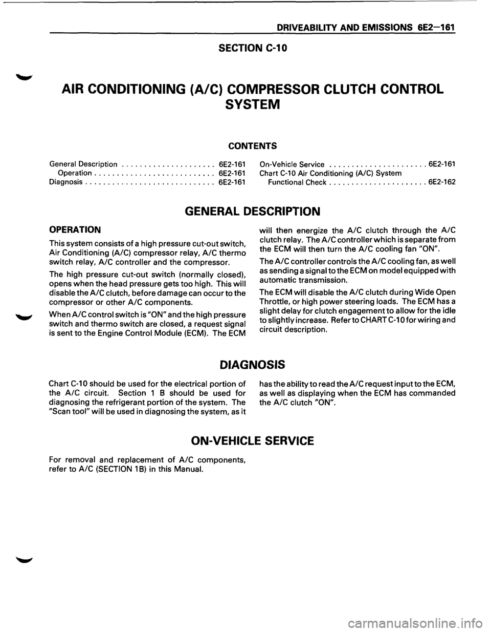
DRIVEABILITV AND EMISSIONS 6E2-161
SECTION C-1 0
AIR CONDITIONING (A/C) COMPRESSOR CLUTCH CONTROL
SYSTEM
CONTENTS
General Description ..................... 6E2-161 On-Vehicle Service ...................... 6E2-161
Operation ........................... 6E2-161 Chart C-10 Air Conditioning (A/C) System
Diagnosis ............................. 6E2-161 Functional Check ...................... 6E2-162
GENERAL DESCRIPTION
OPERATION
This system consists of a high pressure cut-out switch,
Air Conditioning (A/C) compressor
relay, A/C thermo
switch relay, A/C controller and the compressor.
The high pressure cut-out switch
(normally closed),
opens when the head pressure gets too high. This will
disable
the A/C clutch, before damage can occur to the
compressor or other
A/C components.
When
A/C control switch is "ON" and the high pressure
switch and thermo switch are
closed, a request signal
is sent to the Engine Control Module (ECM). The ECM
will then energize the A/C clutch through the A/C
clutch relay. The A/C controller which is separate from
the ECM will then turn the A/C cooling fan "ON".
The A/C controller controls the A/C cooling fan, as well
as sending a signal to the ECM on model equipped with
automatic transmission.
The
ECM will disable the A/C clutch during Wide Open
Throttle,
or high power steering loads. The ECM has a
slight delay for clutch engagement to allow for the idle
to slightly increase. Refer to CHART C-1 0 for wiring and
circuit description.
DIAGNOSIS
Chart C-10 should be used for the electrical portion of
the A/C circuit. Section 1 B should be used for
diagnosing the refrigerant portion of the system. The
"Scan tool" will be used in diagnosing the system, as it
has the ability to read the A/C request inputto the ECM,
as well as displaying when the ECM has commanded
the
A/C clutch "ON".
ON-VEHICLE SERVICE
For removal and replacement of A/C components,
refer to
A/C (SECTION 1 B) in this Manual.
Page 859 of 1928
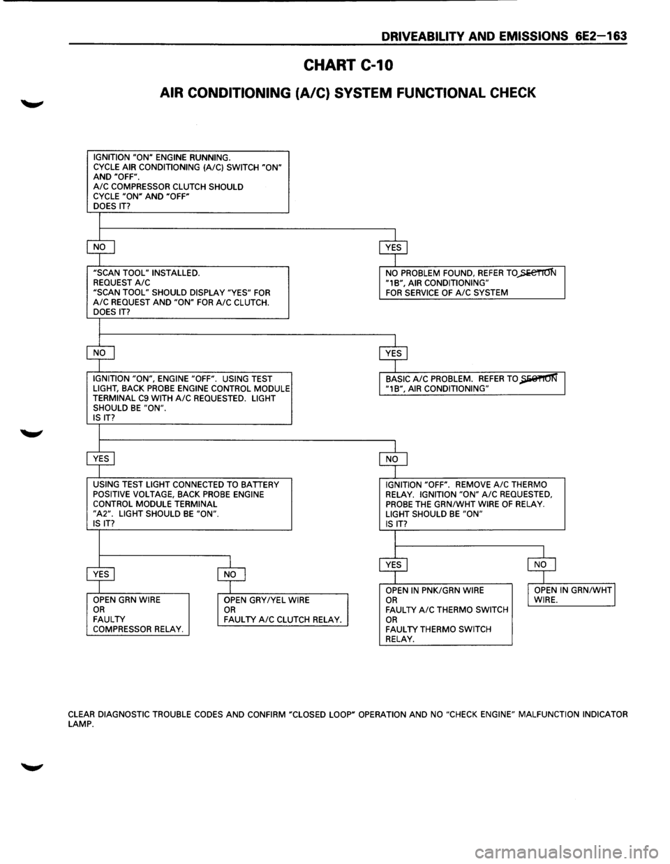
DRIVEABILITV AND EMISSIONS 6E2-163
CHART C-10
AIR CONDITIONING (A/C) SYSTEM FUNCTIONAL CHECK
IGNITION "ON" ENGINE RUNNING.
CYCLE AIR CONDITIONING (A/C) SWITCH "ON" AND "OFF". A/C COMPRESSOR CLUTCH SHOULD
CYCLE "ON" AND "OFF"
DOES IT?
$
$
"SCAN TOOL" INSTALLED.
NO PROBLEM FOUND, REFER TO)>e€TIO'N REQUEST A/C "1B", AIR CONDITIONING"
"SCAN TOOL" SHOULD DISPLAY "YES" FOR FOR SERVICE OF A/C SYSTEM A/C REQUEST AND "ON" FOR A/C CLUTCH.
DOES IT?
$
$
IGNITION "ON", ENGINE "OFF". USING TEST BASIC A/C PROBLEM. REFER TO~ LIGHT, BACK PROBE ENGINE CONTROL MODULE "1B", AIR CONDITIONING"
TERMINAL C9 WITH A/C REQUESTED. LIGHT
SHOULD BE "ON". IS IT?
$ $
USING TEST LIGHT CONNECTED TO BATTERY IGNITION "OFF". REMOVE A/C THERMO
POSITIVE VOLTAGE, BACK PROBE ENGINE RELAY. IGNITION "ON" A/C REQUESTED, CONTROL MODULE TERMINAL PROBE THE GRN/WHT WIRE OF RELAY. "A2". LIGHT SHOULD BE "ON". LIGHT SHOULD BE "ON" IS IT?
IS IT?
I
$ $
~ $ OPEN IN PNK/GRN WIRE I OPEN IN GRN/WHTJ OPEN GRN WIRE
OPEN GRY/YEL WIRE OR WIRE. OR OR FAULTY A/C THERMO SWITCH FAULTY FAULTY A/C CLUTCH RELAY. OR COMPRESSOR RELAY. FAULTY THERMO SWITCH RELAY.
CLEAR DIAGNOSTIC TROUBLE CODES AND CONFIRM "CLOSED LOOP" OPERATION AND NO "CHECK ENGINE" MALFUNCTION INDICATOR LAMP.
Page 879 of 1928
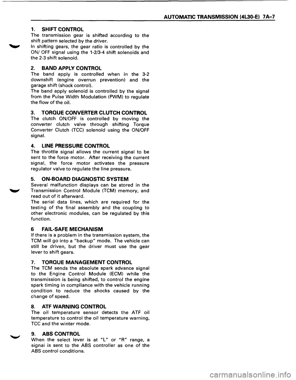
1. SHIFT CONTROL
The transmission gear is shifted according to the
shift pattern selected by the driver.
~ In shifting gears, the gear ratio is controlled by the
ON/ OFF signal using the 1-2/3-4 shift solenoids and
the 2-3 shift solenoid.
2. BAND APPLY CONTROL
The band apply is controlled when in the 3-2
downshift (engine overrun prevention) and the
garage shift (shock control).
The band
apply solenoid is controlled by the signal
from the Pulse Width Modulation (PWM) to regulate
the
flow of the oil.
3. TORQUE CONVERTER CLUTCH CONTROL
The clutch ON/OFF is controlled by moving the
converter clutch valve through shifting Torque
Converter Clutch
(TCC) solenoid using the ON/OFF
signal.
4. LINE PRESSURE CONTROL
The throttle signal allows the current signal to be
sent
to the force motor. After receiving the current
signal, the force motor activates the pressure
regulator valve to regulate the line pressure.
5. ON-BOARD DIAGNOSTIC SYSTEM
Several malfunction displays can be stored in the
Transmission Control Module (TCM) memory, and
read
out of it afterward.
The serial data lines, which are required for the
testing of the final assembly and the coupling to
other electronic modules, can be regulated by this
function.
6 FAIL-SAFE MECHANISM
If there is a problem in the transmission system, the
TCM will go into a "backup" mode. The vehicle can
still be driven, but the driver must use the gear
lever to shift gears.
7. TORQUE MANAGEMENT CONTROL
The TCM sends the absolute spark advance signal
to the Engine Control Module (ECM) while the
transmission is being shifted, to control the engine
spark timing in compliance with the vehicle running
condition to reduce the shocks caused by the
change of speed.
8. ATF WARNING CONTROL
The oil temperature sensor detects the ATF oil
temperature to control the oil temperature warning,
TCC and the winter mode.
9. ABS CONTROL
When the select lever is at "L" or "R" range, a
signal is sent
to the ABS controller as one of the
ABS control conditions.
AUTOMATIC TRANSMISSION (4L30-E) 7A-7
Page 883 of 1928

AUTOMATIC TRANSMISSION (4L30-E) 7 A-11
FUNCTIONS OF INPUT /OUTPUT COMPONENTS
Components Function
Speed sensor
Senses rotation
of output shaft and feeds the data to Transmission
(fixed
to transmission (T/M)) Control Module (TCM)
Throttle Senses the extent of throttle valve opening and the speed of the throttle
position sensor (TPS) valve lever motion to open the valve and feeds the data to TCM (fed to
(fixed to engine)
Engine Control Module (ECM) also)
I
Brake Switch (SW) Senses whether the driver has pressed the brake pedal or not and feeds
N (fixed
to brake pedal) the
information to TCM
p Kick-down SW (fixed to Senses whether the driver has pushed the accelerator pedal fully or not
u accelerator pedal) and feeds the information to TCM
T Mode
SW (fixed to T/M) Senses the select lever position and feeds the information to TCM
s Power drive SW Senses whether the driver has selected the power mode and feeds the
I (fixed to front console) information to TCM
G T/M
oil temp. sensor
Senses the T/M oil temperature and feeds the data to TCM
N Engine
coolant Senses the engine cooling water temperature and feeds the data to TCM
A temperature
SW (feeds the signal from ECM)
L
Engine speed
signal Feeds the signals monitoring engine speed to TCM from Ignition Control
Module
(fed to ECM also)
Air conditioning Senses whether the air conditioner has been switched on or not and
information feeds the information
to TCM
On-board diagnostic
input By monitoring the Ground (GND), the location of failure is shown on the
T/M
monitor lamp ("CHECK TRANS") by flashing the diagnostic trouble
code
Winter switch
Senses whether the driver has selected the winter mode, and feeds the
(fixed
to front console) information to TCM
Cruise
controller Downshift takes place when Overdrive OFF signal is received from auto
(Overdrive
OFF signal) cruise control unit
Shift
solenoid Selects shift point and gear position suited to the vehicle running con-s 1-2/3-4, 2-3
dition on the basis of TCM output 0 Band apply solenoid
Controls oil flow suited to the vehicle running condition on the basis of L
E TCM output
0 N
Torque
Converter Controls clutch engagement/disengagement suited to the vehicle
u 0 Clutch solenoid running condition on the basis of TCM output
T I Force motor Adjusts the oil pump delivery pressure to line pressure suited to the p D
(Pressure regulator vehicle running condition on the basis of TCM output u valve) T
Power drive mode lamp
Informs the driver whether the vehicle is in power mode or not
s Winter drive mode lamp Informs the driver whether the vehicle is in winter mode or not
I T/M monitor lamp Informs the driver of failure in the system. It also displays the self diagnosis
G
("CHECK TRANS") code.
N Data Link Connector
(DLC) When connected with TECH 1 or tester, can communicate the data for A
L function
check, etc. (fed to ECM also). When TECH 1 is not connected, can
communicate the
signal for torque management with ECM.
Self-diagnosis connector
When short-circuited with the bipolar connector, the T/M monitor lamp
displays
a failure by code.
ATF warning
lamp Lights when ATF oil temperature rises.
ABS signal When the select lever is at "Reverse" or "L" range, sends a signal to the
ABS controller as one of the ABS control conditions.
Page 923 of 1928
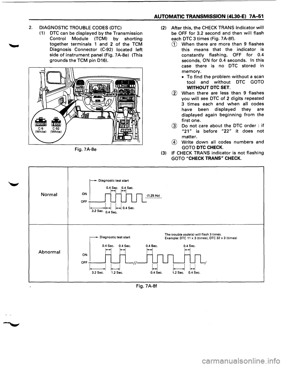
2. DIAGNOSTIC TROUBLE CODES (DTC)
(1) DTC can be displayed by the Transmission
Control Module (TCM) by shorting
together terminals 1 and 2 of the TCM
Diagnosis Connector (C-92)
located left
side of instrument panel (Fig. 7A-8e) (This
grounds the TCM pin D16).
Normal
Abnormal
Fig. 7A-8e
r
Diagnostic test start
0.4 Sec. 0.4 Sec. ~ :..-.! ON I I I I
OFF -----J: : : :
:---f4': -:: ~ 0.4 Sec. 3.2 Sec. 0.4 Sec.
- Diagnostic test start
0.4 Sec. 0.4 Sec.
H H
ONI H H
OFFH H L;;
1*----1 3.2 Sec. 1.2 Sec.
AUTOMATIC TRANSMISSION (4L30-E) 7A-51
(1.25 Hz)
0.4Sec.
' '
' ' ' ' :++l
(2) After this, the CHECK TRANS Indicator will
be OFF for 3.2 second and then will flash
each DTC 3 times (Fig. 7 A-Sf).
CD When there are more than 9 flashes
this means that the indicator is
constantly flashing, OFF for 0.4
seconds, ON for 0.4 seconds. In this
case there is no DTC stored in
memory.
• To find the problem without a scan
tool and without DTC GOTO
WITHOUT DTC SET.
@ When there are less than 9 flashes
you will see DTC of 2 digits repeated
3
times each and when all codes
have been
displayed they are
displayed again beginning from the
first one.
@ Do not care about the DTC order : if
"21" is before "22" it does not
matter.
@ Write down all codes numbers and
GOTO DTC CHECK.
(3) IF CHECK TRANS indicator is not flashing
GOTO
"CHECK TRANS" CHECK.
The trouble code(s) will flash 3 times. Example: DTC 11 x 3 (times), DTC 32 x 3 (times)
0.4 Sec.
' ' I I I I I
1 I I I ~~ 0.4 Sec. 1.2 Sec. 0.4 Sec.
Fig. 7A-8f
Page 925 of 1928
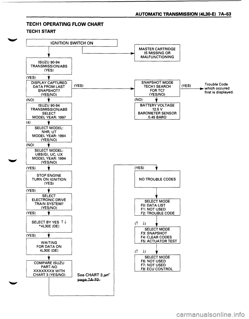
TECH1 OPERATING FLOW CHART
TECH1 START
IGNITION SWITCH ON
ISUZU 90-94
TRANSMISSION/ASS (YES)
(YES)
'
DISPLAY CAPTURED
OAT A FROM LAST (YES) SNAPSHOT?
(YES/NO)
(NO)
'
ISUZU 90-94
TRANSMISSION/ASS SELECT MODEL YEAR: 199?
(4)
'
SELECT MODEL: NHR, UT
MODEL YEAR: 1994 (YES/NO)
(NO)
'
SELECT MODEL: UBS(G), UC, UX
MODEL YEAR: 1994 (YES/NO)
(YES) t
STOP ENGINE TURN ON IGNITION (YES)
(YES)
'
SELECT ELECTRONIC DRIVE
TRAIN SYSTEM? (YES/NO)
(YES)
' SELECT BY YES i ,J.. *4L30E (DE)
(YES)
' WAITING FOR DATA ON 4L30E (DE)
'
COMPARE ISUZU
PART-NO
XXXXXXXX WITH CHART 3 (YES/NO) See CHART 3J)f"'"'"
page 2A +~.
__, -
AUTOMATIC TRANSMISSION (4L30-E) 7 A-53
MASTER CARTRIDGE
IS MISSING OR MALFUNCTIONING
SNAPSHOT MODE
TECH1 SEARCH
FORTC?
(YES/NO)
(NO)
'
BATIERY VOLTAGE 12.5 v BAROMETER SENSOR
0.45 BARO
(YES)
' NO TROUBLE CODES
SELECT MODE FO: OAT A LIST F1: NOT USED F2: TROUBLE CODE
rt ,J..)
SELECT MODE F3: SNAPSHOT F4: CLEAR CODES F5: ACTUATOR TEST
(i ,J..) ,
SELECT MODE F6: NOT USED F7: NOT USED F8: ECU CONTROL
(YES) ...
Trouble Code which occured
first is displayed.