engine coolant ISUZU TROOPER 1995 Workshop Manual
[x] Cancel search | Manufacturer: ISUZU, Model Year: 1995, Model line: TROOPER, Model: ISUZU TROOPER 1995Pages: 1928
Page 1238 of 1928
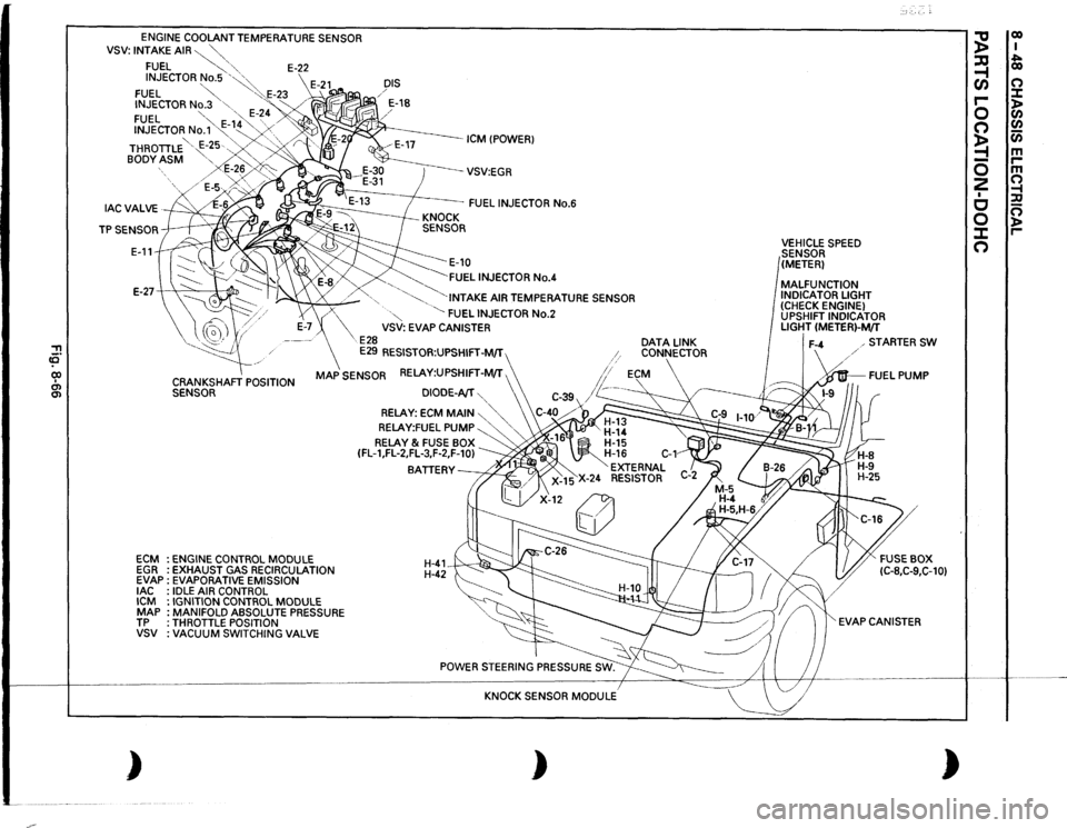
.~·-
, ca· CIO I O'l O'l
ENGINE
COOLANT TEMPERATURE SENSOR
VSV:
INTAKE
AIR~""-"-,
FUEL
~,
'"-
E-22
INJECTOR
No.5
'~~
FUEL
~
"':·.E-23
INJECTOR
No.3
"-
'"<
FUEL
"-
·,,,
E-~
4 /'
INJECTOR
No.'1'~-
1~4 "...
.......
. .......
' '
/
BODY
ASM
"-..'-
>
DIS / / E-18
ICM !POWER)
THROTILE '
E-~5·.-..,
.. '-, ·,/
r
E-2~,,
/E-5v~~;>o~~
--vsv:EGR
FUEL
INJECTOR
No.6
E-11
~E-10 ~FUEL
INJECTOR
No.4
E-27-+
"'
:1
~
.........
_
'-......
"·INTAKE
AIR TEMPERATURE SENSOR
ECM EGR EVAP
lAC
ICM MAP TP vsv )
X
·"
~
FUEL
INJECTOR
No.2
VSV: EVAP CANISTER
E28
E29
RESISTOR:UPSHIFT-M/T
CRANKSHAFT
POSITION
SENSOR
MAP
SENSOR RELAY:UPSHIFT-M/T ,
ENGINE
CONTROL
MODULE
EXHAUST GAS RECIRCULATION
EVAPORATIVE EMISSION IDLE
AIR CONTROL
IGNITION CONTROL
MODULE
MANIFOLD ABSOLUTE PRESSURE
THROTILE POSITION VACUUM
SWITCHING
VALVE
DIODE-AfT
'...,
RELAY:
ECM
MAIN
~"'-.,'...,
RELAY:FUEL
PUMP
'....
'
RELAY
& FUSE BOX
(FL-1,FL-2,FL-3,F-2,F-10)
BATIERY~
H-41 H-42~
KNOCK SENSOR
MODULE
)
DATA
LINK
CONNECTOR
VEHICLE
SPEED
SENSOR
(METER)
MALFUNCTION INDICATOR LIGHT (CHECK ENGINE) UPSHIFT INDICATOR LIGHT
(METER)-M/T
STARTER
SW
·~FUEL
PUMP
EVAP CANISTER
)
~
co I
~
~ co
(/)
0
r-
:::t
0
)> C/)
0
C/)
~
Cii
-
m
0
r-m
2
0
I
~
c
:a
0
0 )>
J:
r-
0
Page 1241 of 1928
w " ~~ O.SLJY ~ ..
2"' a~ u$ ~f~ ~~ ~g~
FENDER-RH II
DUCT II
~~~~~II
DUCT II
INTAKE AIR TEMPERATURE SENSOR
~~ 0~
a; d
0.89
C-1 A&
THROTTLE POSITION
SENSOR
... 5! ., .. ::> 0: ~
m
0.85LIO
~ a d d
li~Ui"o:i UOlUCJI> i;i;i:b ~wuw "'"" ~ ~ g g
"' il " Ill
13
§
; w 0 0: .. 5N ~;:; 8<:1 d~ u"' ~~ ~~ ~~ z< ., .. ~g ~g
~ § :;1 ~ d
0: " Ill d
ENGINE COOLANT
TEMPERATURE
SENSOR
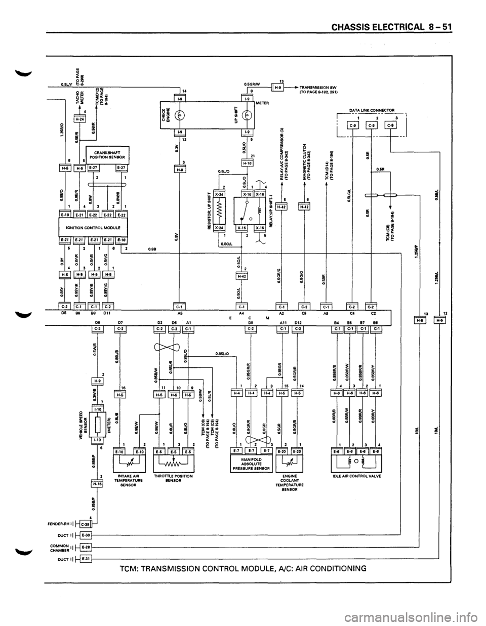
CHASSIS ELECTRICAL 8-51
~ ~ ~w _.,
i£ ~g
~ i ;zf d
d
IIi ~ d .. :b
~~ ~g
~
"' ~ 5I d "'
13 12 H-6 H-6
.. ~ "' ~ il il
!
! ! ~
~ ~ I ~ CD ! ! ~
i
i
TCM: TRANSMISSION CONTROL MODULE, A/C: AIR CONDITIONING
Page 1478 of 1928
8-288 CHASSIS ELECTRICAL
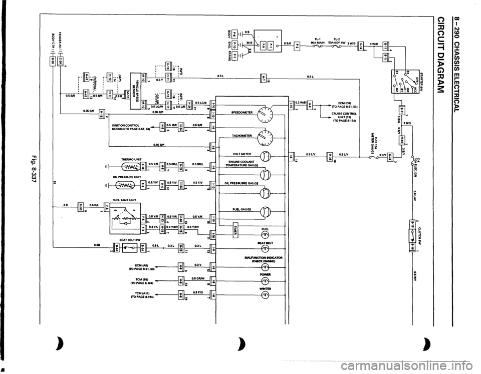
METER AND WARNING/INDICATOR LIGHT
GENERAL DESCRIPTION
The circuit consists of the starter switch, meter assembly, vehicle speed sensor, clutch switch, transmission
switch, lighting switch,
turn signal switch, thermo unit, oil pressure unit, Engine Control Module, fuel tank unit,
4WD
SW, oil pressure switch, parking brake switch, brake fluid switch, seat belt switch and illumination
controller.
The meter ASM contains the speedometer, tachometer, voltmeter, engine coolant temperature gauge, oil
pressure gauge, fuel gauge and warning/indicator lights.
The meter warning/indicator lights and
their bulb sockets are a unit, they are installed from the back of the
speedometer assembly.
Page 1480 of 1928
•
, ce· CX) I w w .....
..
~ m
0
z
0 0 <
m
n
"'
-1
:D
"'
:z:
= ~~ :;; )
O.SIItll 2B
O.&B
ID
-,~
r
-•3
'
.. '
'
' ' IGNITION
CONTROL
MODULECTO
PAGE
S.S1,
531
ECMCASI
(TO PAGE
11-51,
531
TCMihl (TO PAGE
8-1t41
TCMIA111 (TO PAGE
11-1141
~[~} m[i] ~ .:. II
. 0 j[~}l
I'lL,
II"
:----~
.. :~.:,._
:
fill
:~
~~~~ I -··
.!., -
SPEEOOMETER TACHOMETER VOLTMETER ENGINE
COOLANT
TEMPERATURE
GAUGE
OIL PRESSUSRE
GAUGE
FUEL
GAUGE MALFUNCT10N
INDICATOR
lCHECKENGWEI
POWEll -TER
)
O.SL
ECMIDIII
ITO PAGE
11-51,
531
CRUISE
CONTROL UNITI131 ITO PAGE
11-1741
O.SLJY ;;
~ ~ '!' ;;: ~ ~ n ~ ~ )
n -:JJ n c =i c -)> G) :JJ )> 3:
co I N CD 0 (") :.t: > Cl) Cl) Cl) m ,.... m Q , n )> ,....
Page 1484 of 1928
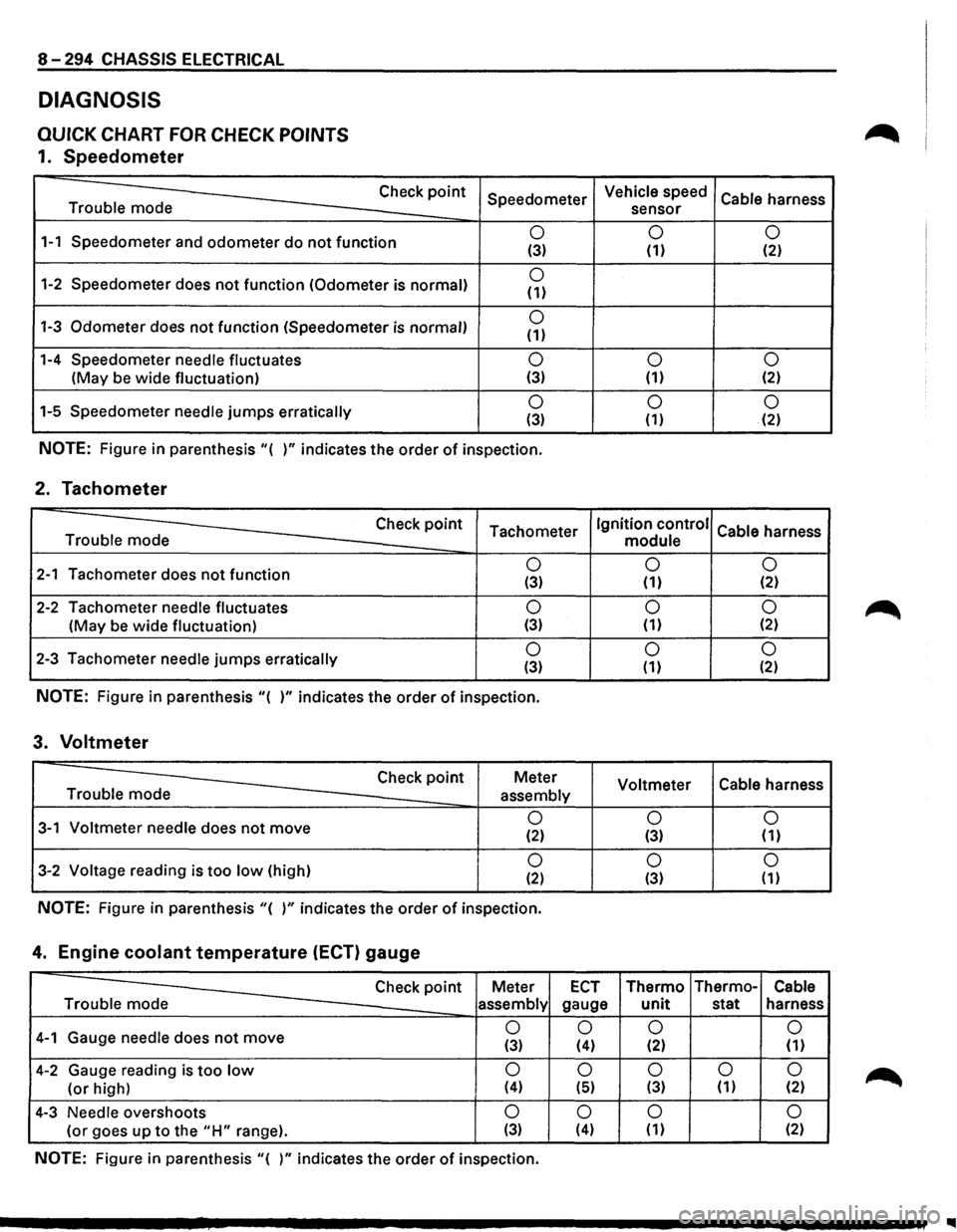
8-294 CHASSIS ELECTRICAL
DIAGNOSIS
QUICK CHART FOR CHECK POINTS
1. Speedometer
Trouble mode Check
point
1-1 Speedometer
and odometer do not function
1-2 Speedometer does not function (Odometer is normal)
1-3 Odometer does not function (Speedometer is normal)
1-4 Speedometer needle fluctuates
(May be wide fluctuation)
1-5 Speedometer
needle jumps erratically Speedometer
0 (3)
0 (1)
0 (1)
0 (3)
0 (3)
NOTE: Figure
in parenthesis "( )" indicates the order of inspection.
2. Tachometer
Check point Tachometer Trouble mode
2-1 Tachometer does not function 0 (3)
2-2 Tachometer needle fluctuates 0
(May be wide fluctuation) (3)
2-3 Tachometer needle jumps erratically 0 (3)
NOTE: Figure in parenthesis "( )" indicates the order of inspection.
3. Voltmeter
Check point Meter
Trouble mode
assembly
3-1 Voltmeter needle does not move 0 (2)
3-2 Voltage reading is too low (high) 0 (2)
NOTE: Figure in parenthesis "( )" indicates the order of inspection.
4. Engine coolant temperature (ECT) gauge
Vehicle speed
Cable harness
sensor
0 0 (1) (2)
0
0 (1) (2)
0 0 (1) (2)
Ignition control
Cable harness
module
0 0
(1) (2)
0 0 (1) {2)
0 0 (1) (2)
Voltmeter Cable
harness
0 0 (3) (1)
0
0 (3) (1)
Check point Meter ECT Thermo Thermo-Cable
Trouble mode
assembly gauge unit stat harness
4-1 Gauge needle does not move 0
0 0
0
(3) (4) (2) (1)
4-2 Gauge reading is too low 0 0 0 0 0
(or high) (4) (5) (3) (1) (2)
4-3 Needle overshoots 0 0 0 0
(or goes up to the "H" range). (3) (4) (1) (2)
NOTE: Figure in parenthesis "( )" indicates the order of inspection.
..
Page 1492 of 1928
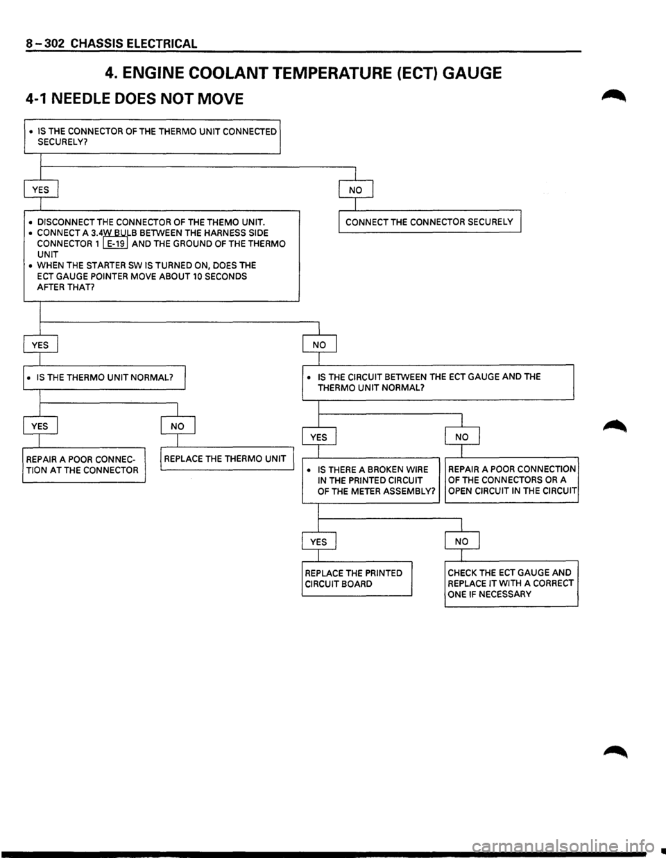
8-302 CHASSIS ELECTRICAL
4. ENGINE COOLANT TEMPERATURE (ECT) GAUGE
4-1 NEEDLE DOES NOT MOVE
• IS THE CONNECTOR OF THE THERMO UNIT CONNECTED SECURELY?
I
YES I
I NO l
I
• DISCONNECT THE CONNECTOR OF THE THEMO UNIT. I CONNECT THE CONNECTOR SECURELY I
• CONNECT A 3.4~B BETWEEN THE HARNESS SIDE CONNECTOR 1 E-19 AND THE GROUND OF THE THERMO
UNIT
• WHEN THE STARTER SW IS TURNED ON, DOES THE
ECT GAUGE POINTER MOVE ABOUT 10 SECONDS AFTER THAT?
I
YES I NO I
1
• IS THE THERMO UNIT NORMAL? I • IS THE CIRCUIT BETWEEN THE ECT GAUGE AND THE
THERMO UNIT NORMAL?
I I
YES I
I NO I I I
YES I l I NO
REPAIR A POOR CONNEC-I REPLACE THE THERMO UNIT I T T
TION AT THE CONNECTOR • IS THERE A BROKEN WIRE REPAIR A POOR CONNECTION
IN THE PRINTED CIRCUIT OF THE CONNECTORS OR A
OF THE METER ASSEMBLY? OPEN CIRCUIT IN THE CIRCUIT
I
I l
YES I NO I
I l
REPLACE THE PRINTED CHECK THE ECT GAUGE AND
CIRCUIT BOARD REPLACE IT WITH A CORRECT
ONE IF NECESSARY
•
Page 1494 of 1928
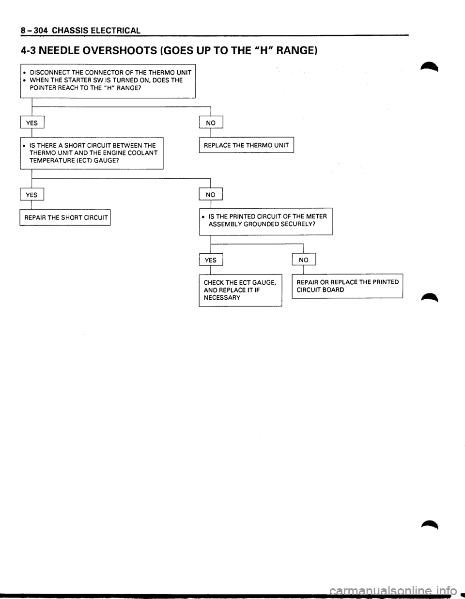
8-304 CHASSIS ELECTRICAL
4-3 NEEDLE OVERSHOOTS (GOES UP TO THE 11H" RANGE)
• DISCONNECT THE CONNECTOR OF THE THERMO UNIT • WHEN THE STARTER SW IS TURNED ON, DOES THE
POINTER REACH TO THE "H" RANGE?
I
I I
YES I NO I
I I
• IS THERE
A SHORT CIRCUIT BETWEEN THE REPLACE
THE THERMO UNIT THERMO UNIT AND THE ENGINE COOLANT TEMPERATURE (ECT) GAUGE?
I
I
I
YES I NO I
I I
REPAIR THE SHORT CIRCUIT I • IS THE PRINTED CIRCUIT OF THE METER
ASSEMBLY GROUNDED SECURELY?
I
I l
YES I NO I
I I
CHECK
THE ECT GAUGE, REPAIR OR REPLACE THE PRINTED
AND REPLACE IT IF CIRCUIT BOARD
NECESSARY
Page 1506 of 1928
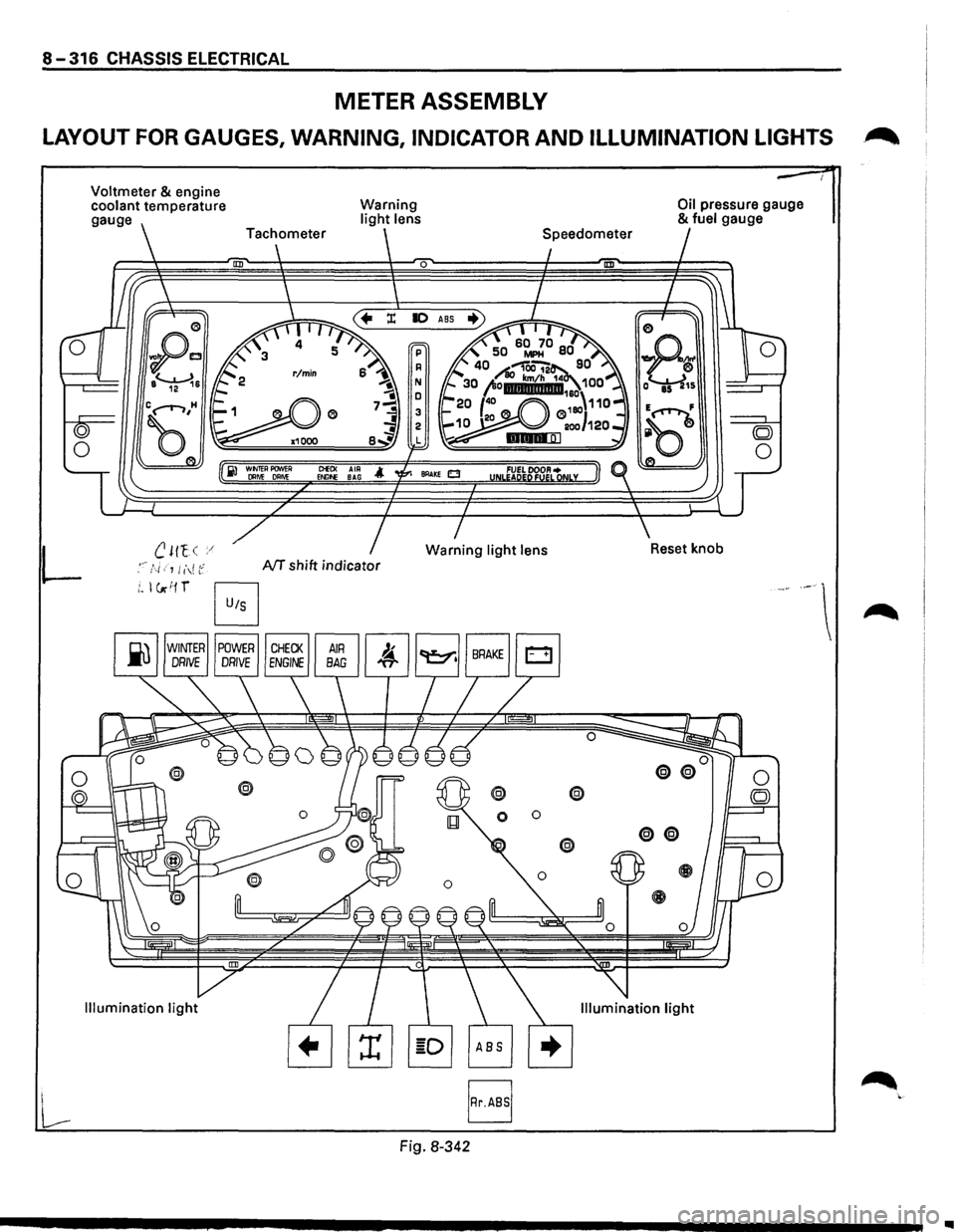
8-316 CHASSIS ELECTRICAL
METER ASSEMBLY
LAYOUT FOR GAUGES, WARNING, INDICATOR AND ILLUMINATION LIGHTS .~
L
Voltmeter & engine
coolant temperature
gauge
B
Warning light lens
0
ClEO< AIR Et.llf>E BAG
NT shift indicator
Fig. 8-342
@ @
0 0
Oil pressure gauge & fuel gauge
..
Page 1507 of 1928
CHASSIS ELECTRICAL 8-317
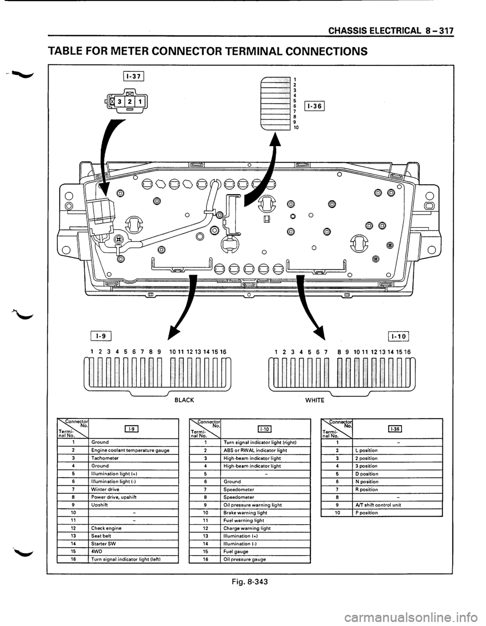
TABLE FOR METER CONNECTOR TERMINAL CONNECTIONS
~-""""""', 1----""'12 1----""'1! 6 1----l 6 [Iill
1----""'1 ~ 9 1---""'l,o
®
0 0
0
® @
0 0 ~
~m© © © © ©'--m ~~0
0 !III
1 2 3 4 5 6 7 8 9 1011 1213141516 1 2 3 4 56 7 8 9 10111213141516
w~~~~~~~~ ~~~~~~m rn~~~~~~ ~~nn~~m
~ I J BLACK WHITE
~r o. DTI -na No. ~
. IJJ:Q] -
. ~ [ill] . -. 1 Ground 1 Turn
signal indicator light (right)
1 -2 Engine coolant temperature gauge 2 ABS or RWAL indicator light 2 L
position
3 Tachometer 3 High-beam indicator light 3 2 position 4
Ground
4 High-beam
indicator light 4 3 position 6 Illumination light (+I 5 -5 D position
6 Illumination light(-) 6 Ground 6 N position 7 Winter drive 7 Speedometer 7 R position 8 Power drive, upshift 8 Speedometer 8 -9 Upshift 9 Oil pressure warning light 9 AfT shift control unit 10 -10 Brake warning light 10 P position 11 -11 Fuel warning light 12 Check engine 12 Charge warning light 13 Seat belt 13 Illumination (+) 14 StarterSW 14 Illumination (-) 15 4WD 15 Fuel gauge 16 Turn signal indicator light (left) 16 Oil pressure gauge
Fig. 8-343
Page 1514 of 1928
8-324 CHASSIS ELECTRICAL
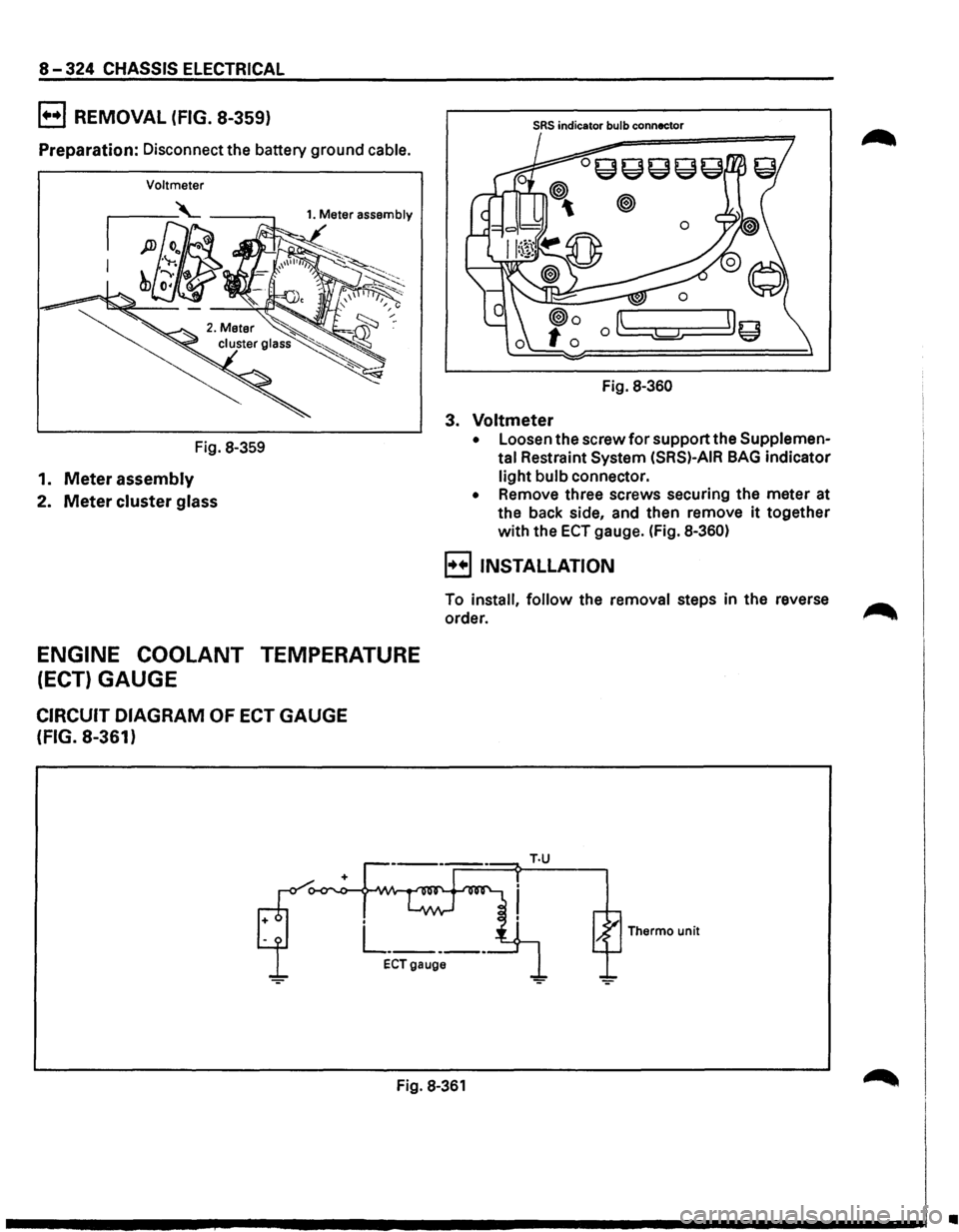
B REMOVAL (FIG. 8-359)
Preparation: Disconnect the battery ground cable.
Voltmeter
Fig. 8-359
1. Meter assembly
2. Meter cluster glass
ENGINE COOLANT TEMPERATURE
(ECT) GAUGE
CIRCUIT DIAGRAM OF ECT GAUGE
(FIG. 8-361)
SRS indicator bulb connector
Fig. 8-360
3. Voltmeter
• Loosen the screw for support the Supplemen
tal
Restraint System (SRS)-AIR BAG indicator
light bulb connector.
• Remove three screws securing the meter at
the back side, and then remove
it together
with the
ECT gauge. (Fig. 8-360)
B INSTALLATION
To install, follow the removal steps in the reverse ....-...
order. ,........
Thermo unit
ECTgauge
Fig. 8-361
•