check engine light ISUZU TROOPER 1995 Workshop Manual
[x] Cancel search | Manufacturer: ISUZU, Model Year: 1995, Model line: TROOPER, Model: ISUZU TROOPER 1995Pages: 1928
Page 22 of 1928
OB-6 MAINTENANCE AND LUBRICATION
BRAKE SYSTEMS OPERATION
Watch for the "BRAKE" light coming on. Other
signs of possible brake trouble are such things as
repeated pulling to one side when braking, unusual
sounds
when braking or between brake
applications,
or increased brake pedal travel. If you
note one of these conditions, repair the system at
once.
For convenience, the
following should be done
when wheels are removed for rotation: Inspect lines
and hoses
for proper hookup, bindings, leaks, crack,
chafing etc.
Inspect disc brake pads for wear and
rotors
for surface condition.
Inspect other brake parts, including parking brake
drums, linings etc., at the same time. Check parking
brake adjustment.
Inspect brakes more often if habit or
conditions
result in frequent braking.
PARKING BRAKE AND TRANSMISSION
PARK MECHANISM OPERATION
Park on a fairly steep hill and hold the vehicle with
the parking brake only. This checks holding ability.
On
automatic transmission vehicles, shifting from
"P" position to the other positions cannot be made
unless
the brake pedal is depressed when the key
switch is in
"ON" position or the engine running.
WARNING
•
Before checking starter safety switch
operation below,
be sure to have enough
room around the
vehicle. Then firmly apply
both the parking brake and the regular brake.
Do not
use the accelerator pedal. If the engine
starts, be ready
to turn off the key promptly.
Take these precautions because the vehicle
could move
without warning and possibly
cause personal injury
or property damage.
STARTER SAFETY SWITCH OPERATION
(AUTOMATIC TRANSMISSION)
Check by trying to start the engine in each gear
while setting the parking brake and the foot brake.
The starter
should crank only in "P" (Park) or "N"
(Neutral).
STARTER SAFETY SWITCH OPERATION
(MANUAL TRANSMISSION)
To check, place the shift lever in "Neutral", push
the clutch pedal halfway and try to start. The starter
should not crank. The starter should crank only
when the clutch pedal is fully depressed.
ACCELERATOR LINKAGE LUBRICATION
Lubricate the accelerator pedal fulcrum pin with
chassis grease.
STEERING AND SUSPENSION
INSPECTION
Inspect front and rear suspension and steering
system
for damaged, loose or missing parts or signs
of wear. Inspect power steering lines and hoses for
proper hookup, binding, leaks, cracks, chafing, etc.
BODY AND CHASSIS LUBRICATION
Lubricate the key lock cylinders, the hood latch, the
hood and door hinges, the door check link, the
parking cable guides,
the underbody contact points,
and the linkage.
PROPELLER SHAFT INSPECTION AND
LUBRICATION
Lubricate sliding yoke and universal joints with
grease containing MOS2 (disulfide molybdenum
type grease) at the interval shown in the
Maintenance Schedule. Check for play in normal
direction of rotation of sliding yoke and universal
joints. Also check
propeller shaft flange-to-pinion
bolts for proper torque of 63 N·m (46 lb·ft) for front
and rear propeller shaft.
AUTOMATIC TRANSMISSION FLUID
INSPECTION
Check the lubricant level every 7,500 miles (12,000
km) and add lubricant
if necessary.
Under harsh operating conditions, such as constant
driving in heavy city traffic during
hot weather, or in
hilly or mountainous terrain, change the transmission
fluid and service the
sump filter after every 20,000
miles (32,000 km) of operation.
AUTO CRUISE CONTROL INSPECTION
Check to see if the clearance between cruise link and
accelerator is normal. Also check that the vacuum
hoses are routed and connected properly.
CLUTCH LINES AND HOSES INSPECTION
Check lines and hoses for proper attachment,
binding, leaks, cracks, chafing, deterioration, etc.
Any questionable parts should be replaced or
repaired at once. When abrasion or wear is evident
on lines or hoses, the cause must be corrected.
..
Page 77 of 1928
6.
7.
Perform system leak test.
• Charge the system with approx. 200 g (0.44
lbs) of HFC-134a.
• Make sure the high pressure valve of the
manifold gauge is closed.
• Check
to ensure that the degree of pressure
does
not change.
• Check for refrigerant leaks by using a HFC-
134a leak detector.
• If a leak occurs, recover the refrigerant. Repair
the leak, and start all over again from the first
step of evacuation.
If no leaks are found, continue charging re
frigerant to the air conditioning system.
• Charge the refrigerant until the scale reading
decreases
by the amount of the charge
specified.
Specified
amount g (lbs.) I 750 (1.65)
• If charging the system becomes difficult:
( 1) Run the engine at idle and close all the
vehicle doors.
(2) Turn A!C switch "ON".
(3) Set the fan switch to its highest position.
(4) Set air source selector lever to "CIRC".
(5) Slowly open the low side valve on the
manifold gauge set.
WARNING: BE ABSOLUTELY SURE NOT TO
OPEN THE HIGH PRESSURE VALVE OF THE
MANIFOLD GAUGE. SHOULD THE HIGH
PRESSURE VALVE BE OPENED, THE HIGH
PRESSURE REFRIGERANT WOULD FLOW
BACKWARD, AND
THIS MAY CAUSE THE
REFRIGERANT CONTAINER TO BURST.
8. When finished with the refrigerant charging,
close the low pressure valve of the manifold
gauge and container valve.
9. Check for refrigerant leaks.
AIR CONDITIONING 18 -23
Checking
the A/C system
1. Run the engine and close all the vehicle doors.
2. Turn A!C switch "ON", set the fan switch to its
highest position, set air source
lever to "CIRD"
and set temperature lever to full cool position.
3. Check the high and low pressure of the manifold
gauge.
• Immediately after charging refrigerant, both
high and low pressure are slightly high, but
they settle down to the pressure guidelines
shown below:
Ambient temperature: 25-30°C (77 -86°F)
Pressure guidelines:
• High-pressure side;
Approx. 1372.9-1863.3kPa (199.1-270.2psi)
• Low-pressure side;
Approx. 147.1-294.2 kPa (21.3-42.7 psi)
• If an abnormal pressure is found, refer to
"CHECKING REFRIGERANT SYSTEM WITH
MANIFOLD
GAUGE" in this section.
4. Put your hand in front of the air outlet and move
the temperature control lever of the control
panel
to different positions. Check if the outlet
temperature changes as selected by the control
knob.
Page 142 of 1928
381 - 4 POWER STEERING GEAR AND PUMP
ON-VEHICLE SERVICE
MAINTENANCE
The hydraulic system should be kept clean and fluid
level in the reservoir should be checked at regular
intervals
and fluid added when required. Refer to
"MAINTENANCE AND LUBRICATION" in section OB
ofthe manual for type offluid to be used and intervals
for filling.
If the system contains some dirt, flush it as detailed
later
in this section. If it is exceptionally dirty, both the
pump and the gear must be completely disassembled
before further usage.
All tubes, hoses, and fittings should be inspected for
leakage at regular intervals. Fittings must be tight.
Make sure the clips, clamps and supporting tubes and
hoses are in
place and properly secured.
Power steering hoses and lines must not be twisted,
kinked or tightly bent. Air in the system will cause
spongy action and noisy operation. When a hose is
disconnected
or when fluid is lost, for any reason, the
system must be bled after refilling. Refer to "Bleeding
the Power Steering System" in this section.
FLUID LEVEL
1. Run the engine until the power steering fluid
reaches normal operating temperature, about
55°C (130°F), then shut the engine off.
2. Check the level of fluid in the reservoir.
3. If the fluid level is low, add power steering fluid
as specified in "MAINTENANCE AND LUBRI
CATION" in Section OB to the proper level and
install the receiver cap.
4. When checking the fluid level after the steering
system has been serviced,
air must be bled from
the system. Refer to "Bleeding the Power
Steering
System" in this section.
BLEEDING THE POWER STEERING
SYSTEM
When a power steering pump or gear has been
installed, or an oil line has been disconnected, the air
that has entered the system must be bled out before
the vehicle is operated. If air is allowed to remain in
the power steering fluid system, noisy and
unsatisfactory operation of the system may result.
BLEEDING PROCEDURE
When bleeding the system, and any time fluid is
added
to the power steering system, be sure to use
only power steering fluid as specified in
"MAINTENANCE AND LUBRICATION" in section OB.
1. Fill the pump fluid reservoir to the proper level
and let the fluid settle for at least two minutes.
2. Start the engine and let it run for a few seconds.
Do
not turn the steering wheel. Then turn the
engine off.
3. Add fluid if necessary.
4. Repeat the above procedure until the fluid level
remains constant after running the engine.
5. Raise the front end of the vehicle so that the
wheels are off the ground.
6. Start the engine. Slowly turn the steering wheel
right and left, lightly contacting the wheel stops.
7. Add power steering fluid if necessary.
8. Lower the vehicle and turn the steering wheel
slowly from lock to lock.
9. Stop the engine. Check the fluid level and refill
as required.
10.
If the fluid is extremely foamy, allow the vehicle
to stand a few minutes and repeat the above
procedure.
~ INSPECT
• Belt for tightness.
• Pulley for looseness or damage. The pulley
should not wobble with the engine running.
• Hoses so they are not touching any other parts
of the vehicle.
• Fluid level
and fill to the proper level.
FLUSHING THE POWER STEERING
SYSTEM
1. Raise the front end of the vehicle off the ground
until the wheels are free to turn.
2. Remove the fluid return line at the pump inlet
connector and plug the connector port on the
pump.
Position the line toward a large container to
catch the draining fluid.
3. While running the engine at idle, fill the reservoir
with new power steering fluid. Turn the steering
wheel in both directions. DO NOT contact wheel
stops or hold the wheel in a corner, or fluid will
stop and the pump will be in pressure relief mode.
A sudden
overflow from the reservoir may
develop if the wheel is held at a stop.
4. Install all the lines and hoses. Fill the system with
new power steering fluid and bleed the system
as described in "Bleeding The Power Steering
System". Operate the engine for about 15
minutes.
Remove the
pump return line at the pump inlet
and plug the connection on the pump. While
refilling the reservoir, check the draining fluid for
contamination. If foreign material is still evident,
replace all lines, disassemble and clean or replace
the power steering system components. Do not
re-use any drained power steering fluid.
~
~
Page 245 of 1928
REAR AXLE 48-3
DIAGNOSIS OF REAR AXLE NOISE
Many noises that seem to come from the rear axle
actually
originate from other sources such as tires,
road surface, wheel bearings, engine, transmission,
muffler,
or body drumming. Investigate to find the
source
ofthe noise before disassembling the rear axle.
Rear axles,
like any other mechanical device, are not
absolutely quiet but should be considered quiet unless
some abnormal noise is present.
To make a systematic check
for axle noise, observe the
following:
1. Select a level asphalt road to reduce tire noise and
body drumming.
2. Check rear axle lubricant level to assure correct
level, and then drive the vehicle far enough to
thoroughly warm up the rear axle lubricant.
3. Note the speed at which noise occurs. Stop the
vehicle and put the transmission in neutral. Run
the engine speed
slowly up and down to
determine if the noise is caused by exhaust,
muffler noise, or other engine conditions.
4. Tire noise changes with different road surfaces;
axle noises do not. Temporarily inflate all tires to
344
kPa (50 psi) (for test purposes only). This will
change noise caused by tires but will not affect
noise caused by the rear
axle.
Rear axle nose usually stops when coasting at
speeds under
48 km/h (30 mph); however, tire
noise continues
with a lower tone. Rear axle noise
usually changes when comparing pull and coast,
but tire noise stays about the same.
Distinguish between tire noise and rear
axle noise
by noting
if the noise changes with various
speeds
or sudden acceleration and deceleration.
Exhaust and
axle noise vary under these
conditions,
while tire noise remains constant and
is more pronounced at speeds
of 32 to 48 km/h
(20 to 30 mph). Further check for tire noise by
driving the vehicle
over smooth pavements or dirt
roads (not gravel) with the tires at normal
pressure.
If the noise is caused by tires, it will
change noticeably with changes in road surface.
5. Loose or rough front wheel bearings will cause
noise
which may be confused with rear axle
noise; however, front wheel bearing noise does
not change when comparing drive and coast.
Light application
of the brake while holding
vehicle speed steady
will often cause wheel
bearing noise to diminish. Front wheel bearings
may be checked for noise by jacking up the
wheels and spinning them
or by shaking the
wheels
to determine if bearings are loose.
6. Rear suspension rubber bushings and spring
insulators dampen
out rear axle noise when
correctly installed. Check to see that there is no
link or rod loosened or metal-to-metal contact.
7. Make sure that there is no metal-to-metal contact
between the
floor and the frame.
After the noise has been determined to be in the axle,
the type of axle noise should be determined, in order to
make any necessary repairs.
GEAR NOISE
Gear noise (whine) is audible from 32 to 89 km/h (20 to
55 mph) under four driving conditions.
1. In drive under acceleration or heavy pull.
2. Driving under load or under constant speed.
3. When using enough throttle to keep the vehicle
from driving the engine while the vehicle slows
down gradually (engine still pulls slightly).
4. When coasting with the vehicle in gear and the
throttle closed. The gear noise is
usually more
noticeable between 48 and 64
km/h (30 and 40
mph) and 80 and 89 km/h (50 and 55 mph).
BEARING NOISE
Bad bearings generally produce a rough growl or
grating sound, rather than the whine typical of gear
noise. Bearing noise frequently
"wow-wows" at
bearing rpm, indicating a bad pinion
or rear axle side
bearing. This noise can
be confused with rear wheel
bearing noise.
REAR WHEEL BEARING NOISE
Rear wheel bearing noise continues to be heard while
coasting at low speed with transmission in the neutral.
Noise may diminish by gentle braking. Jack up the rear
wheels, spin them by hand and
listen for noise at the
hubs. Replace any faulty
wheel bearings.
KNOCK AT LOW SPEEDS
Low speed knock can be caused by worn universal
joints or a side gear hub counter bore in the cage that is
worn oversize. Inspect and replace universal joints or
cage and side gears as required.
BACKLASH CLUNK
Excessive clunk on acceleration and deceleration can
be caused by a worn rear axle pinion shaft, a worn
cage, excessive clearance between the axle and the
side gear splines, excessive clearance between the
side gear hub and the counterbore in the cage,
worn
pinion and side gear teeth, worn thrust washers, or
excessive drive pinion and ring gear backlash.
Remove
worn parts and replace as required. Select
close-fitting parts when possible. Adjust pinion and
ring gear backlash.
Page 322 of 1928
SA-2 HYDRAULIC BRAKES
BRAKE SYSTEM DIAGNOSIS
ROAD TESTING THE BRAKES
Brake Test
Brakes should be tested on a dry, clean, reasonably
smooth and
level roadway. A true test of brake
performance cannot be made
if the roadway is
wet, greasy
or covered with loose dirt so that all
tires do not grip the road equally. Testing will also
be adversely affected if the roadway is crowned so
as to throw the weight of the vehicle toward
wheels on one side or if the roadway is so rough
that wheels tend to bounce. Test the brakes at dif
ferent vehicle speeds with both light and heavy
pedal pressure; however, avoid locking the wheels
and sliding the tires. Locked wheels and sliding
tires do not indicate brake efficiency, since heavily
braked but turning wheels will stop the vehicle in
less distance than locked wheels. More tire-to-road
friction is present
with a heavily braked turning tire
then
with a sliding tire.
The standard brake system is designed and
balanced
to avoid locking the wheels except at very high
deceleration
levels.
It
is designed this way because the shortest stopping
distance and best
control is achieved without brake
lock-up.
Because of high deceleration capability, a firmer pedal
may be felt at higher deceleration levels.
External Conditions That Affect Brake
Performance
1.
2.
3.
Tires: Tires having unequal contact and grip on
the road
will cause unequal braking. Tires must
be equally inflated, identical in size, and the tread
pattern
of right and left tires must be approxi
mately equal.
Vehicle loading:
A heavily loaded vehicle requires
more braking effort.
Wheel Alignment: Misalignment of the wheels,
particularly
in regard to excessive camber and
caster,
will cause the brakes to pull to one side.
BRAKE FLUID LEAKS
With engine running at idle and the transmission in
"Neutral", depress the brake pedal and hold a constant
foot pressure on the pedal. If pedal gradually falls
away with the constant pressure, the hydraulic system
may be leaking.
Check the master cylinder fluid level. While a slight
drop in reservoir level will result from normal lining
wear, an abnormally low level in reservoir indicates a
leak in the system. The hydraulic system may be
leaking internally as well as externally. Refer to
"Master Cylinder Inspection". Also, the system may
appear
to pass this test but still have slight leakage. If
fluid level
is normal, check the vacuum booster
push rod
length. If an incorrect length push rod is
found, adjust
or replace the push rod. Check the
brake
pedal travel and the parking brake adjust
ment.
When checking the
fluid level, the master cylinder fluid
level
may be low from the "MAX" mark if the front and
rear
linings are worn. This is not abnormal.
WARNING LIGHT OPERATION
When the ignition switch is in the START position,
the
"BRAKE" warning light should glow and go off
when the ignition switch returns to the ON position.
The
following conditions will activate the "BRAKE"
light:
1. Parking brake applied. The light should be on
whenever the parking brake is applied and the
ignition switch is on.
2. Low fluid level. A low fluid level in the master
cylinder will turn the "BRAKE" light on (Except
Rear
Wheel Antilock Brake System (RWAL)
model).
3. During engine cranking the "BRAKE" light
should
remain on. This notifies the driver that
the warning circuit is operating properly.
4. In the event of a front or rear system malfunc
tion (RWAL model only).
5. In the event of RWAL malfunction (RWAL
model only. Refer to Section 5A3).
ANTILOCK BRAKE SYSTEM (RWAL or
ABS}
Refer to Section 5A3 or 5A4 for inspection and di
agnosis procedure of the hydraulic unit.
..
Page 326 of 1928
5A-6 HYDRAULIC BRAKES
NOTE:
Do not allow the fluid level in the reservoir to go below
the half-way mark.
12. Reconnect the brake pipe
(j) to the master
cylinder and tighten the pipe.
13. Depress the brake pedal
slowly once and hold it
depressed.
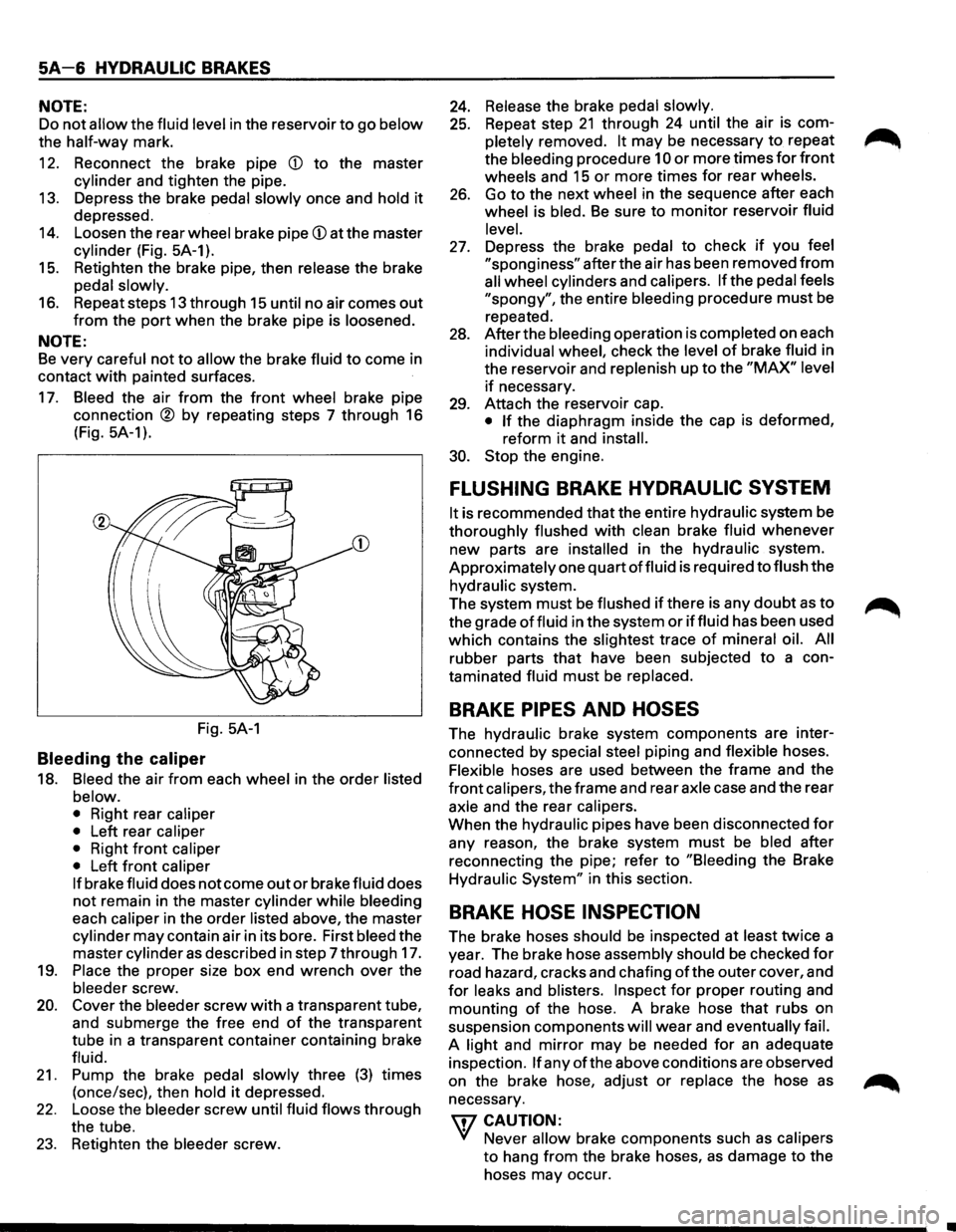
14. Loosen the rear wheel brake pipe (j) at the master
cylinder (Fig. 5A-1).
15. Retighten the brake pipe, then release the brake
pedal
slowly.
16. Repeat steps 13 through 15 until no air comes out
from the port when the brake pipe is loosened.
NOTE:
Be very careful not to allow the brake fluid to come in
contact
with painted surfaces.
17. Bleed the air from the front wheel brake pipe
connection
® by repeating steps 7 through 16
(Fig.
5A-1 ).
Fig. 5A-1
Bleeding the caliper
18. Bleed the air from each wheel in the order listed
below.
• Right rear caliper
• Left rear caliper
• Right front caliper
• Left front caliper
If brake fluid does not come out or brake fluid does
not remain in the master cylinder while bleeding
each
caliper in the order listed above, the master
cylinder may contain air in its bore. First bleed the
master cylinder
as described in step 7 through 17.
19.
Place the proper size box end wrench over the
bleeder screw.
20. Cover the bleeder screw with a transparent tube,
and submerge the free end
of the transparent
tube in a transparent container containing brake
fluid.
21. Pump the brake pedal slowly three (3) times
(once/sec), then
hold it depressed.
22. Loose the bleeder screw until fluid flows through
the tube.
23. Retighten the bleeder screw.
24. Release the brake pedal slowly.
25. Repeat step 21 through 24 until the air is com
pletely removed.
It may be necessary to repeat
the bleeding procedure
10 or more times for front
wheels and 15 or more times for rear wheels.
26. Go to the next wheel in the sequence after each
wheel is bled.
Be sure to monitor reservoir fluid
level.
27. Depress the brake pedal to check if you feel
"sponginess" after the air has been removed from
all wheel cylinders and calipers. If the pedal feels
"spongy", the entire bleeding procedure must be
repeated.
28. After the bleeding operation is completed on each
individual wheel, check the level
of brake fluid in
the reservoir and replenish up to the
"MAX" level
if necessary.
29. Attach the reservoir cap.
• If the diaphragm inside the cap is deformed,
reform
it and install.
30. Stop the engine.
FLUSHING BRAKE HYDRAULIC SYSTEM
It is recommended that the entire hydraulic system be
thoroughly flushed with clean brake fluid whenever
new parts are
installed in the hydraulic system.
Approximately one quart
of fluid is required to flush the
hydraulic system.
The system
must be flushed if there is any doubt as to
the grade
of fluid in the system or iffluid has been used
which contains the
slightest trace of mineral oil. All
rubber parts that have been subjected to a con
taminated fluid
must be replaced.
BRAKE PIPES AND HOSES
The hydraulic brake system components are inter
connected
by special steel piping and flexible hoses.
Flexible hoses are used between the frame and the
front calipers, the frame and rear axle case and the rear
axle and the rear calipers.
When the hydraulic pipes have been disconnected
for
any reason, the brake system must be bled after
reconnecting the pipe; refer to
"Bleeding the Brake
Hydraulic
System" in this section.
BRAKE HOSE INSPECTION
The brake hoses should be inspected at least twice a
year. The brake hose assembly should
be checked for
road hazard, cracks and chafing ofthe outer cover, and
for leaks and blisters. Inspect for proper routing and
mounting
of the hose. A brake hose that rubs on
suspension components
will wear and eventually fail.
A light and mirror may be needed for an adequate
inspection.
If any of the above conditions are observed
on the brake hose, adjust
or replace the hose as
necessary.
\fl CAUTION:
'V Never allow brake components such as calipers
to hang from the brake hoses, as damage to the
hoses may occur.
Page 333 of 1928
HYDRAULIC BRAKES SA-13
BRAKE PEDAL ASSEMBL V
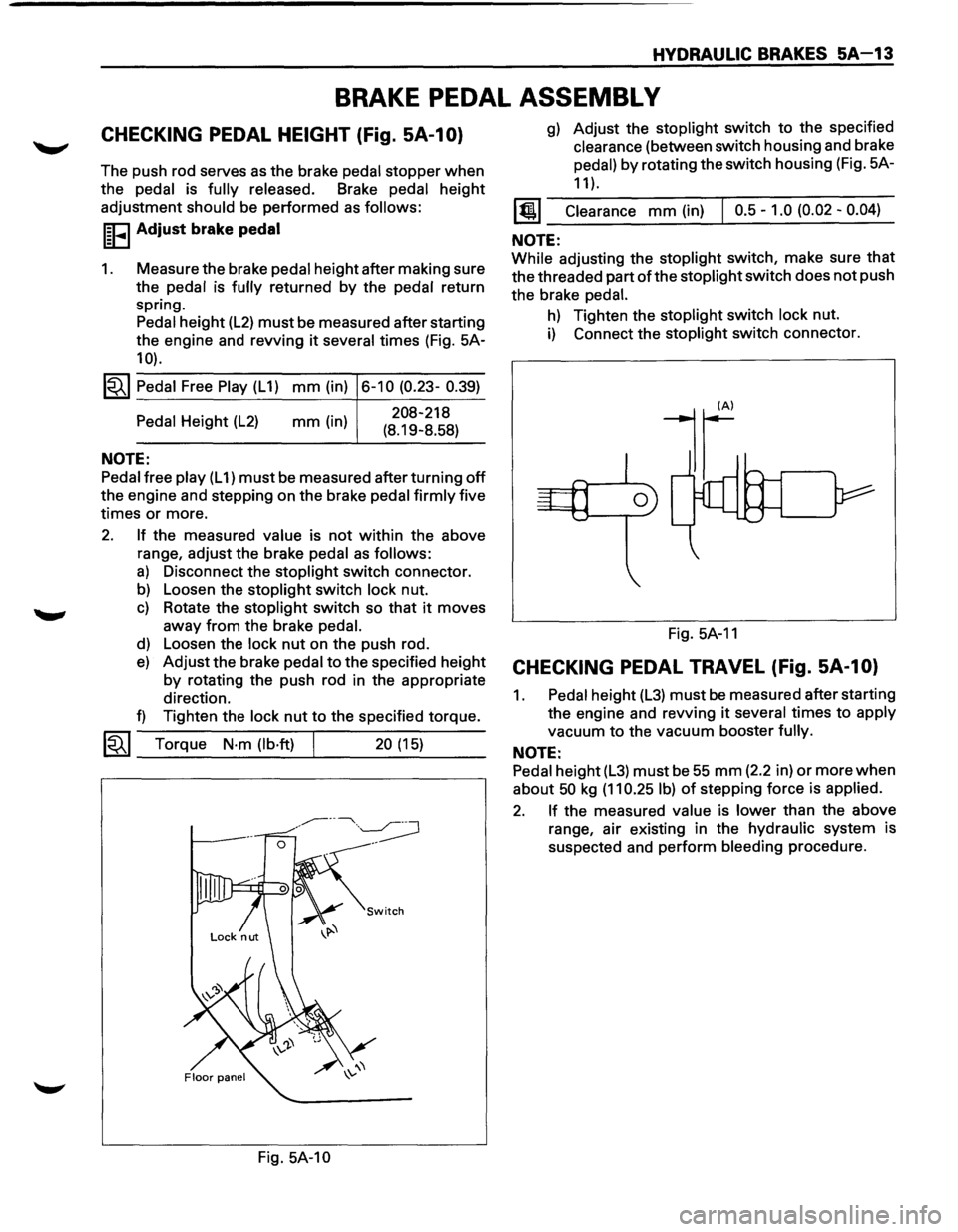
CHECKING PEDAL HEIGHT (Fig. SA-1 0)
The push rod serves as the brake pedal stopper when
the pedal is fully released. Brake pedal height
adjustment
should be performed as follows:
I~FI Adjust brake pedal
1. Measure the brake pedal height after making sure
the pedal is
fully returned by the pedal return
spring. Pedal height
(L2) must be measured after starting
the engine and revving
it several times (Fig. 5A-
10).
1~1 Pedal Free Play (L 1) mm (in) 6-10 (0.23- 0.39)
Pedal Height (L2)
NOTE:
mm (in) 208-218
(8.19-8.58)
Pedal free play (L 1) must be measured after turning off
the engine and stepping on the brake pedal firmly five
times
or more.
2. If the measured value is not within the above
range, adjust the brake
pedal as follows:
a) Disconnect the stoplight switch connector.
b) Loosen the stoplight switch lock nut.
c) Rotate the stoplight switch so that it moves
away
from the brake pedal.
d) Loosen the lock nut on the push rod.
e) Adjust the brake pedal to the specified height
by rotating the push rod in the appropriate
direction.
f) Tighten the lock nut to the specified torque.
~~~ Torque N·m (lb·ft) 20 (15) --------~----~---
Fig. 5A-10
g) Adjust the stoplight switch to the specified
clearance (between switch housing and brake
pedal)
by rotating the switch housing (Fig. 5A-
11 ).
1@1 Clearance mm (in) I 0.5-1.0 (0.02-0.04)
NOTE:
While adjusting the stoplight switch, make sure that
the threaded part of the stoplight switch does not push
the brake
pedal.
h) Tighten the stoplight switch lock nut.
i) Connect the stoplight switch connector.
Fig.
5A-11
CHECKING PEDAL TRAVEL (Fig. SA-1 0)
1. Pedal height (L3) must be measured after starting
the engine and revving
it several times to apply
vacuum
to the vacuum booster fully.
NOTE:
Pedal height (L3) must be 55 mm (2.2 in) or more when
about 50 kg (11 0.25 I b) of stepping force is applied.
2. If the measured value is lower than the above
range, air existing in the hydraulic system is
suspected and perform bleeding procedure.
Page 369 of 1928
REAR WHEEL ANTILOCK BRAKE SYSTEM 5A3-1
SECTION 5A3
REAR WHEEL ANTILOCK BRAKE SYSTEM
(RWAL}
w CAUTION:
• All brake attaching fasteners are an important attaching part in that they could affect performance of vital
parts and systems, and/or could result in major repair expense. They must be replaced with one of the same
part
number or with an equivalent part if replacement becomes necessary. Do not use replacement parts of
lesser quality or substitute design. Torque values must be used as specified during reassembly to assure
proper retention of these parts.
CONTENTS
Introduction . . . . . . . . . . . . . . . . . . . . . . . . . 5A3· 1
General Description . .
. . . . . . . . . . . . . . .
5A3· 1
Rear
Wheel Antilock (RWAL) Control
Parts Location . .
. . . . . . . . . . . . . . . . .
5A3· 5
System Diagram . .
. . . . . . . . . . . . . . . . . . . .
5A3· 6
Rear
Wheel Antilock (RWAL) System
Diagnostics . .
. . . . . . . . . . . . . . . . . . . . . .
5A3· 7
On-Vehicle Service . .
. . . . . . . . . . . . . . . . .
5A3·38
RWAL Electronic Brake Control
Module (EBCM) Replacement ....... 5A3-38
Antilock
(Isolation/Dump) Valve
Replacement ..................... 5A3-39
Speed Sensor Replacement
.......... 5A3-40
Main Data and Specifications ........... 5A3-41
Torque Specifications
............... 5A3-41
INTRODUCTION
This section deals with the complete diagnosis and
services
for vehicles equipped with rear wheel
antilock.
For service information regarding all other
components
of the brake system, refer to "Hydraulic
Brakes"
(Sec. SA), "Brake Booster System" (Sec. SA 1)
or "Disc Brakes" (Sec. SA2) of this Manual.
GENERAL DESCRIPTION
The rear wheel anti lock system (RWAL) is designed to
reduce rear wheel lock-up during a severe brake
application,
thus maintaining rear end stability. The
system functions
by regulating the rear hydraulic
brake line pressure. The pressure regulation is
accomplished
by an anti lock valve which is located on
the
front right side of engine room. The anti lock valve
is made up of two valves, a dump valve which releases
pressure into an accumulator and an isolation valve
which maintains rear brake pressure. The valve is
controlled
by a microcomputer which is part of the
Electronic Brake Control Module (EBCM). The
EBCM is mounted at the
front of the center
console. Under severe brake application, as pressure
is
applied to the brake pedal, the EBCM is designed to
permit the valve to do one of three functions or a
combination
of all three. The EBCM will allow the valve
to either maintain the same amount of hydraulic
pressure, release hydraulic pressure through the
dump valve into the accumulator or increase the
pressure by
pulsing the isolation valve.
The EBCM operates by receiving signals from the
speed sensor (which
is located in the differential
carrier), combination
valve and the brake light switch.
The RWAL system is connected
to the RWAL indicator
light located on the dash. An indication of the RWAL
operation and a
bulb check is performed each time the
ignition is turned
"ON". The indicator light will remain
on
for about two seconds. A RWAL system
malfunction is indicated if the RWAL indicator light
stays on, or comes on during driving. To determine the
specific
trouble, refer to "RWAL System Diagnostics"
in this section.
Page 371 of 1928
REAR WHEEL ANTILOCK BRAKE SYSTEM 5A3-3
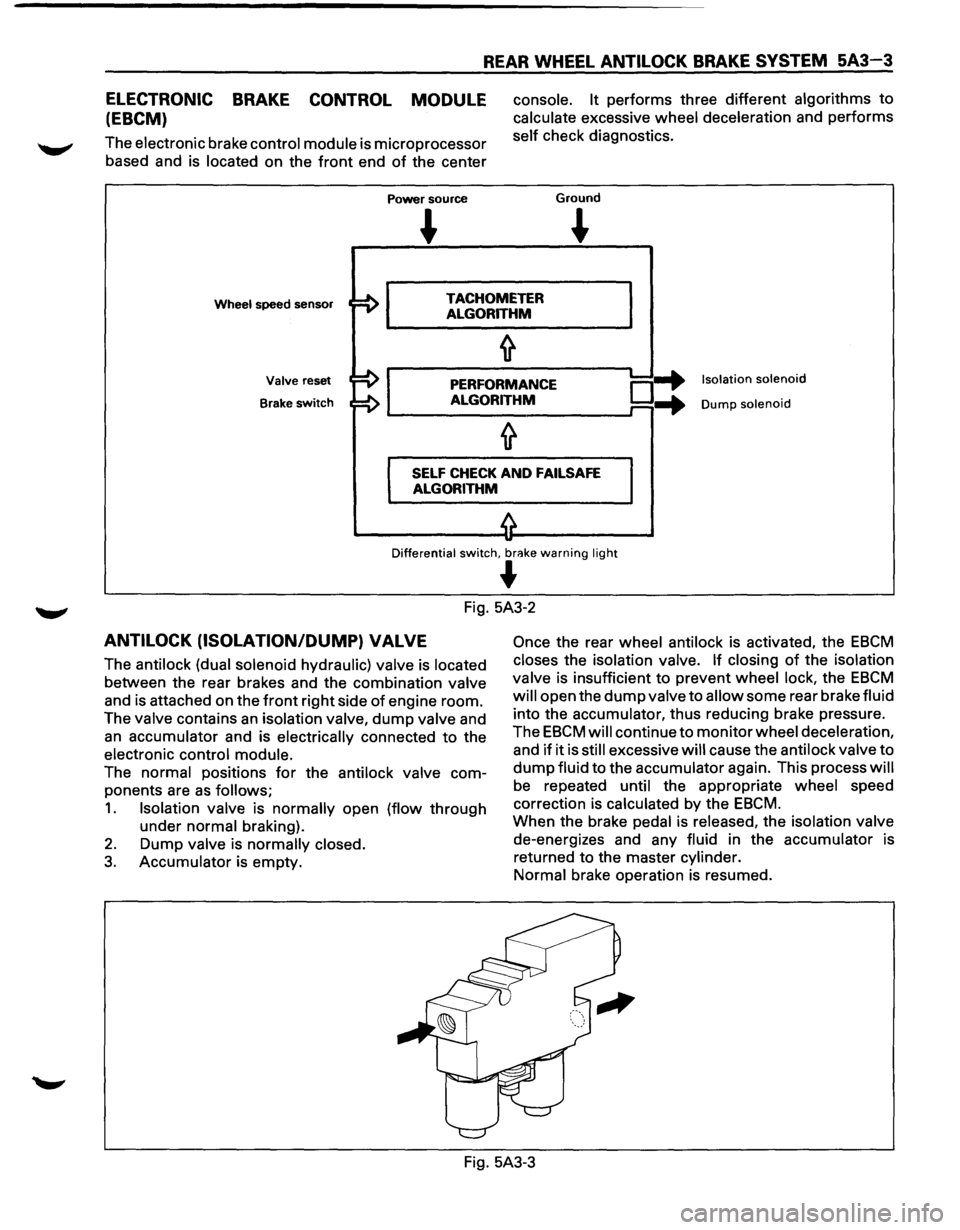
ELECTRONIC BRAKE CONTROL MODULE
(EBCM)
The electronic brake control module is microprocessor
based and is located on the
front end of the center
Power source
console. It performs three different algorithms to
calculate excessive wheel deceleration and performs
self check diagnostics.
Ground
~
Wheel speed sensor TACHOMETER
ALGORITHM
Valve reset
Brake
switch
PERFORMANCE
ALGORITHM o-+ ...
Isolation solenoid
Dump solenoid
SELF CHECK AND FAILSAFE
ALGORITHM
Differential switch, br<'!ke warning light
~
Fig. 5A3-2
ANTILOCK (ISOLATION/DUMP) VALVE
The antilock (dual solenoid hydraulic) valve is located
between the rear brakes and the combination valve
and is attached on the
front right side of engine room.
The valve contains
an isolation valve, dump valve and
an accumulator and is electrically connected to the
electronic control module.
The normal positions
for the antilock valve com
ponents are
as follows;
1. Isolation valve is normally open (flow through
under normal braking).
2. Dump valve is normally closed.
3. Accumulator is empty.
Once the rear wheel antilock is activated, the EBCM
closes the isolation valve. If closing of the isolation
valve is insufficient to prevent wheel lock, the
EBCM
will open the dump valve to allow some rear brake fluid
into the accumulator, thus reducing brake pressure.
The
EBCM will continue to monitor wheel deceleration,
and
if it is still excessive will cause the antilock valve to
dump fluid to the accumulator again. This process will
be repeated until the appropriate wheel speed
correction is calculated by the
EBCM.
When the brake pedal is released, the isolation valve
de-energizes and any fluid in the accumulator is
returned to the master cylinder.
Normal brake operation is resumed.
Fig. 5A3-3
Page 375 of 1928
REAR WHEEL ANTILOCK BRAKE SYSTEM 5A3-7
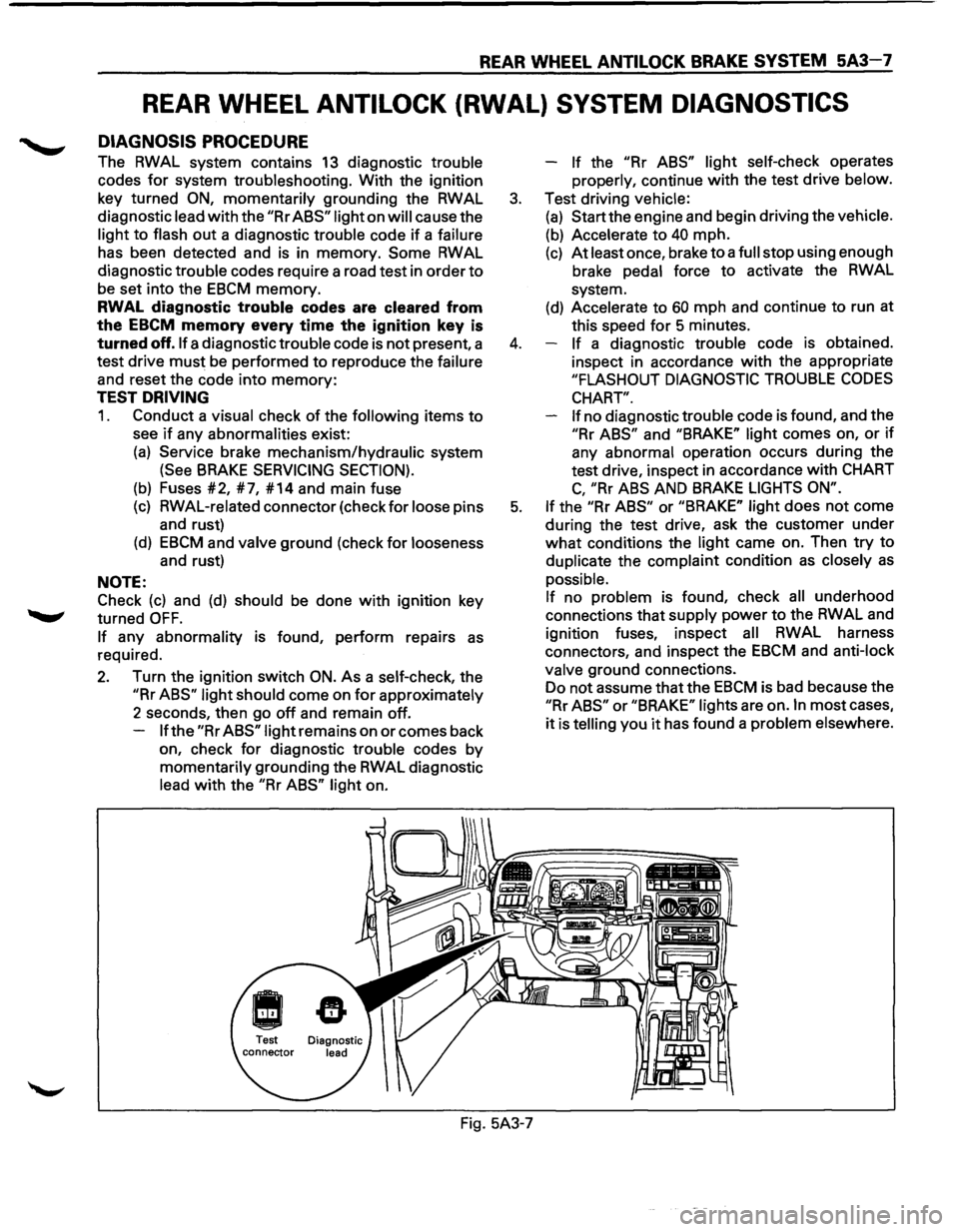
REAR WHEEL ANTILOCK (RWAL) SYSTEM DIAGNOSTICS
DIAGNOSIS PROCEDURE
The RWAL system contains 13 diagnostic trouble
codes
for system troubleshooting. With the ignition
key turned
ON, momentarily grounding the RWAL
diagnostic lead
with the "Rr ABS" light on will cause the
light
to flash out a diagnostic trouble code if a failure
has been detected and is in memory.
Some RWAL
diagnostic trouble codes require a road test in order
to
be set into the EBCM memory.
RWAL diagnostic trouble codes are cleared from
the
EBCM memory every time the ignition key is
turned off. If a diagnostic trouble code is not present, a
test drive
must be performed to reproduce the failure
and reset the code into
memory:
TEST DRIVING
1. Conduct a visual check of the following items to
see if any abnormalities exist:
(a) Service brake mechanism/hydraulic system
(See BRAKE SERVICING SECTION).
(b) Fuses #2, #7, #14 and main fuse
(c) RWAL-related connector (check for loose pins
and rust)
(d) EBCM and valve ground (check for looseness
and rust)
NOTE:
Check
(c) and (d) should be done with ignition key
turned
OFF.
If any abnormality is found, perform repairs as
required.
2. Turn the ignition switch ON. As a self-check, the
"Rr ABS" light should come on for approximately
2 seconds, then go
off and remain off.
If the "Rr ABS" light remains on or comes back
on, check
for diagnostic trouble codes by
momentarily grounding the RWAL diagnostic
lead
with the "Rr ABS" light on. -
If the "Rr
ABS" light self-check operates
properly, continue
with the test drive below.
3. Test driving vehicle:
(a) Start the engine and begin driving the vehicle.
(b) Accelerate to 40 mph.
(c) At least once, brake to a full stop using enough
brake pedal force
to activate the RWAL
system.
(d) Accelerate to 60 mph and continue to run at
this speed
for 5 minutes.
4. If a diagnostic trouble code is obtained.
inspect in accordance
with the appropriate
"FLASHOUT DIAGNOSTIC TROUBLE CODES
CHART".
If
no diagnostic trouble code is found, and the
"Rr ABS" and "BRAKE" light comes on, or if
any abnormal operation occurs during the
test drive, inspect in accordance
with CHART
C, "Rr ABS AND BRAKE LIGHTS ON".
5. If the "Rr ABS" or "BRAKE" light does not come
during the test drive, ask the customer under
what conditions the light came on. Then try to
duplicate the complaint condition
as closely as
possible.
If no problem is found, check all underhood
connections that supply power
to the RWAL and
ignition fuses, inspect
all RWAL harness
connectors, and inspect the
EBCM and anti-lock
valve ground connections.
Do not assume that the
EBCM is bad because the
"Rr ABS" or "BRAKE" lights are on. In most cases,
it is telling you it has found a problem elsewhere.
Fig. 5A3-7