engine coolant ISUZU TROOPER 1995 Manual Online
[x] Cancel search | Manufacturer: ISUZU, Model Year: 1995, Model line: TROOPER, Model: ISUZU TROOPER 1995Pages: 1928
Page 835 of 1928
RESULTS OF INCORRECT OPERATION
An open or ground in the Ignition Control (I C) or bypass
circuits
will set a Diagnostic Trouble Code (DTC) 42 and
cause the engine
to run on the Ignition Control Module
(ICM)
timing.
The Engine
Control Module (ECM) uses information
from the Intake Air Temperature (IAT) and engine
coolant sensors in addition to revolution per minute
(rpm) to
calculate spark advance as follows:
• Cold
engine -more spark advance.
• Engine under minimum load based on rpm and
low amount of air flow = more spark advance.
• Hot engine = less spark advance.
• Engine under heavy load based on rpm and high
air
flow = less spark advance.
HOW DIAGNOSTIC TROUBLE CODE (DTC)
42 IS DETERMINED
When the system is running on the ICM, that is, no
voltage on the bypass line, the ICM grounds (GND) the
IC signal. The ECM expects to see no voltage on the IC
line during this condition.lf it sees a voltage, it sets DTC
42 and will not go into the IC mode.
DRIVEABILITY AND EMISSIONS 6E2-139
When the rpm for IC is reached (about 400 rpm) the
ECM applies 5 volts to the bypass line and the IC should
no longer be grounded in the ICM so the IC voltage
should
be varying.
An open in the
IC circuit while running, will result in the
engine continuing to run, but in a back-up
ig~it~on
timing mode (module timing) at a calculated t1mmg
value
and the malfunction indicator lamp will not be
"ON".
If
the IC circuit is shorted to GND, the "Check Engine"
malfunction
indicator lamp will be turned "ON", and a
DTC 42 will be set and the engine will operate in
module timing. Either condition may cause poor
performance and reduced
fuel economy.
If the bypass line is open or GND, the ICM will not
switch to IC mode so the IC voltage will be low and DTC
42 will be set.
If the IC line is grounded, the ICM will switch to IC, but
because the line isGNDtherewill be no ICsignai.A DTC
42 will be set.
DIAGNOSIS
If the engine cranks but will not run, CHART A-3 will be
used to determine if the Electronic Ignition (EI) system
is the cause
of the problem or if it is another part of the
fuel injection system.
If DTC 42 is set, that DTC chart should be used for
diagnosis. If no DTC is set and the ignition system is
suspected, use
CHART C4-D ("EI" Misfire) for
diagnosis.
DIAGNOSTIC TROUBLE CODE (DTC) 12
DTC 12 is used during the on-board diagnostic system
check procedure to test the
DTC display ability of the
ECM. This diagnostic trouble code indicates that the
ECM is not receiving the engine speed (REFERENCE)
signal. This occurs with the ignition key "ON" and the
engine not running.
The "reference"
signal also triggers the fuel injection
system.
Without the "reference" signal the engine
cannot run.
ON-VEHICLE SERVICE
ELECTRONIC IGNITION (EI) ASSEMBLY
1••1 REMOVE OR DISCONNECT
1. Negative battery cable
2. "EI" electrical connectors (3)
3. Spark plug wires. (Note wire positions to proper
coils) (6)
4. "EI" assembly to bracket bolts (3)
5. "EI" assembly from Intake Plenum.
1••1 INSTALL OR CONNECT
1. "EI" assembly bracket to Intake Plenum
Tighten bolts to 25 N·m (19 lb·ft)
2. Spark plug wires to correct spark plugs
3. "EI" electrical connectors
4. Negative battery cable
Page 847 of 1928
DRIVEABILITY AND EMISSIONS 6E2-151
SECTION C-7
EXHAUST GAS RECIRCULATION (EGR) SYSTEM
CONTENTS
GENERAL DESCRIPTION ................. 6E2-151
Operation . . . . . . . . . . . . . . . . . . . . . . . . . . . 6E2-151
Exhaust Gas
Recirculation (EGR) Valve
Check . .
. . . . . . . . . . . . . . . . . . . . . . . . . . 6E2-152
Exhaust Gas
Recirculation (EGR)
Backpressure Transducer (BPT) Check 6E2-152
Exhaust Gas
Recirculation (EGR)
Vacuum Switch Valve (VSV) Solenoid
Check . .
. . . . . . . . . . . . . . . . . . . . . . . . . . 6E2-152
DIAGNOSIS ........................... 6E2-153
ON-VEHICLE SERVICE .................... 6E2-153
Exhaust Gas
Recirculation (EGR)
Manifold Passage ................... 6E2-153
Exhaust Gas
Recirculation (EGR)
Valve Replacement .................. 6E2-153
Exhaust
Gas Recirculation (EGR)
Backpressure Transducer (BPT)
Replacement ....................... 6E2-153
Exhaust Gas
Recirculation (EGR)
Vacuum Switch Valve (VSV) Replacement . 6E2-153
CHART C-7A Exhaust Gas
Recirculation (EGR)
System Check ...................... 6E2-154
GENERAL DESCRIPTION
The Exhaust Gas Recirculation (EGR) System controls
the formation of NOx (Oxides of Nitrogen) Emissions
by
recirculating the exhaust gases into the combustion
chamber. This is done through the intake
manifold.
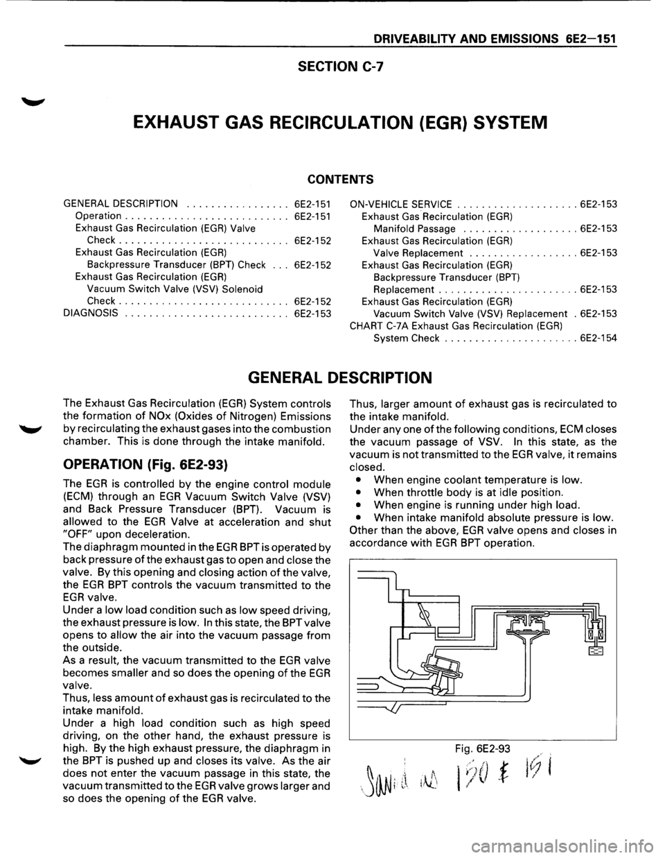
OPERATION (Fig. 6E2-93)
The EGR is controlled by the engine control module
(ECM) through an EGR Vacuum Switch Valve (VSV)
and Back Pressure Transducer (BPT). Vacuum is
allowed to the EGR Valve at acceleration and shut
"OFF" upon deceleration.
The diaphragm mounted in the EGR BPT is operated by
back pressure
of the exhaust gas to open and close the
valve. By this opening and closing action of the valve,
the EGR BPT controls the vacuum transmitted to the
EGR valve.
Under
a low load condition such as low speed driving,
the exhaust pressure is
low. In this state, the BPTvalve
opens to allow the air into the vacuum passage from
the outside.
As a
result, the vacuum transmitted to the EGR valve
becomes smaller and so does the opening of the EGR
valve.
Thus, less amount of exhaust gas is recirculated to the
intake
manifold.
Under
a high load condition such as high speed
driving, on the
other hand, the exhaust pressure is
high. By the high exhaust pressure, the diaphragm in
the
BPT is pushed up and closes its valve. As the air
does
not enter the vacuum passage in this state, the
vacuum transmitted
to the EGR valve grows larger and
so does the opening
of the EGR valve.
Thus, larger amount of exhaust gas is recirculated to
the intake manifold.
Under
any one ofthe following conditions, ECM closes
the vacuum passage of VSV. In this state, as the
vacuum is not transmitted
to the EGR valve, it remains
closed.
•
When engine coolant temperature is low.
•
When throttle body is at idle position.
• When engine is running under high load.
•
When intake manifold absolute pressure is low.
Other
than the above, EGR valve opens and closes in
accordance
with EGR BPT operation.
Fig. 6E2-93
i
.
,::·)I)' t
/
..f-l
Page 853 of 1928
DRIVEABILITY AND EMISSIONS 6E2-157
SECTION C-8
SHIFT INDICATOR LIGHT (MIT ONLY)
CONTENTS
General Description . . . . . . . . . . . . . . . . . . . . . 6E2-157 Diagnosis ............................. 6E2-157
Purpose ............................ 6E2-157 Transmission Switch Functional Check ..... 6E2-157
Operation . . . . . . . . . . . . . . . . . . . . . . . . . . . 6E2-157 Clutch Switch Functional Check ........... 6E2-157
Chart C-8 Manual Transmission (M/T)
Shift Light ........................... 6E2-158
GENERAL DESCRIPTION
PURPOSE
The shift indicator light is a device which is installed in
the instrument
panel to urge the driver to up shiftatthe
proper moment. This insures operations for best fuel
economy.
OPERATION
It turns on as soon as vehicle conditions become
suitable for operation in the next higher gear, and turns
off as the clutch is released for up shift.
The engine parameters used
to activate the shift
indicator
light are engine speed, engine load and
engine
coolant temperature. The engine load is sensed
as a function of Throttle Body (TB) position by a sensor
built into the TB. The
shift indicator
light turns on when the following
conditions exist simultaneously:
1. Engine coolant temperature is hotter than -s·c.
2. TB is not in idle position.
3. The engine load, is not greater than the
predetermined
values.
4. The transmission gear is in any forward position
other then 5th, that is, either
of the two
transmission switches (1st-2nd switch and 3rd-
4th switch) is on. 1st-2nd switch turns on
when the
transmission is in 1st-2nd, and 3rd-4th switch
turns on when the transmission 3rd
or 4th.
5. The clutch is engaged (clutch switch is "ON").
The control system schematic is shown in CHART
C-8.
DIAGNOSIS
See CHART C-8.
TRANSMISSION SWITCH FUNCTIONAL
CHECK
1. Connector from the suspected faulty switch.
2. An ohmmeter across terminals of switch.
3. Operate gear shift.
4. Ohmmeter should indicate open (infinity) then
closed (00).
5. Replace switch if not operating as described.
CLUTCH SWITCH FUNCTIONAL CHECK
1. Remove clutch switch.
2. Ohmmeter to terminal of clutch switch.
3. Operate the clutch switch.
4. Ohmmeter should read "closed" (00) then
"open" (infinity) when clutch switch is pressed.
5. Replace switch if not operating as described.
Page 854 of 1928
6E2-158 DRIVEABILITV AND EMISSIONS
CHART C-8
MANUAL TRANSMISSION (M/T) SHIFT LIGHT CHECK
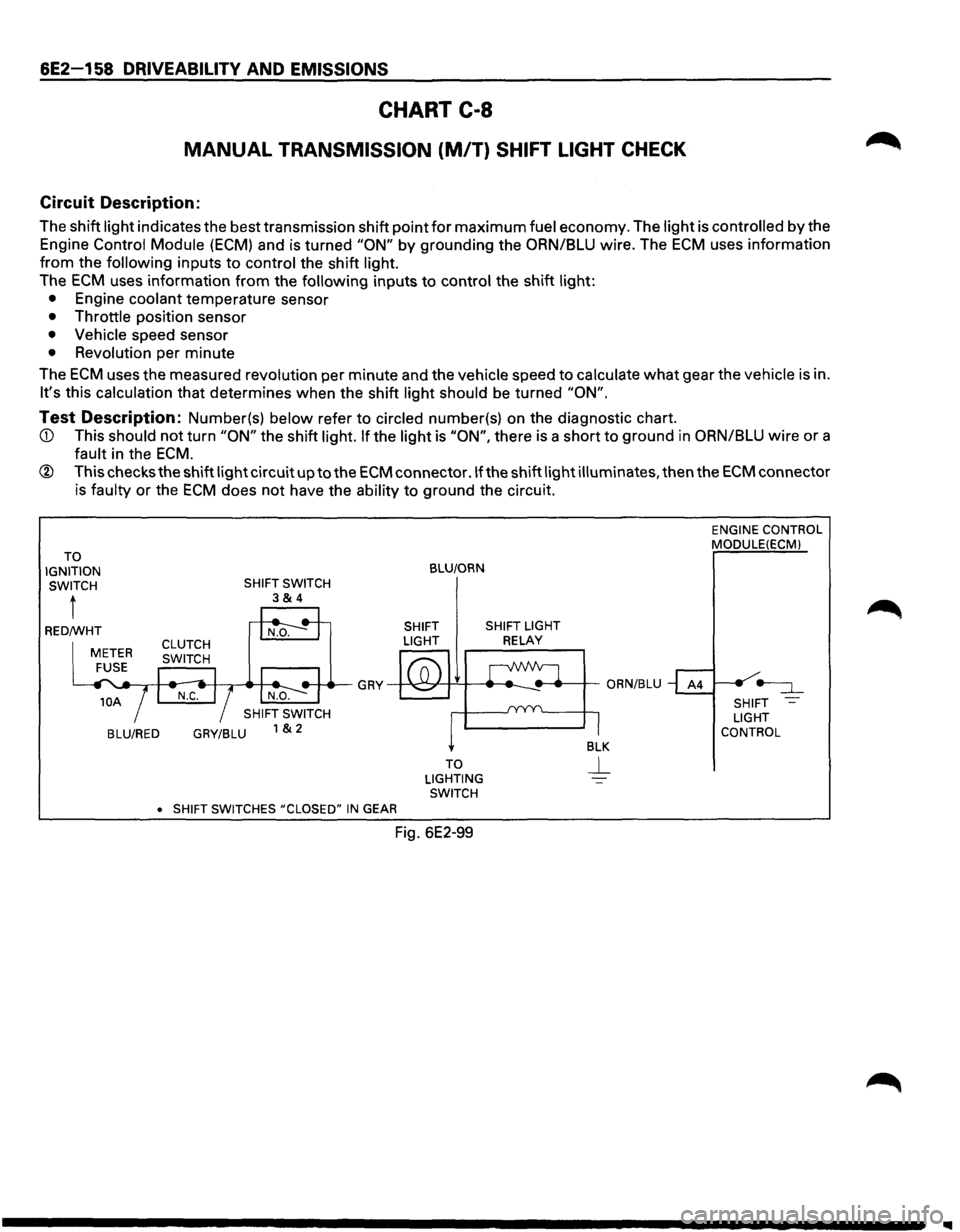
Circuit Description:
The shift light indicates the best transmission shift point for maximum fuel economy. The light is controlled by the
Engine Control Module
(ECM) and is turned "ON" by grounding the ORN/BLU wire. The ECM uses information
from the following inputs to control the shift light.
The
ECM uses information from the following inputs to control the shift light:
• Engine coolant temperature sensor
• Throttle position sensor
• Vehicle speed sensor
• Revolution per minute
The
ECM uses the measured revolution per minute and the vehicle speed to calculate what gear the vehicle is in.
It's this calculation that determines when the shift light should be turned "ON".
Test Description: Number(s) below refer to circled number(s) on the diagnostic chart.
ECM.
® This checks the shift light circuit up to the ECM connector .If the shift light illuminates, then the ECM connector
is faulty
or the ECM does not have the ability to ground the circuit.
TO
IGNITION SWITCH
t
BLU/RED GRY/BLU
•
SHIFT SWITCHES #CLOSED" IN GEAR
BLU/ORN
SHIFT SHIFT LIGHT
LIGHT
RELAY
TO
LIGHTING SWITCH
Fig. 6E2-99
ENGINE CONTROL
MODULE(ECMl
SHIFT
LIGHT
CONTROL
Page 876 of 1928
•
"'Tl c3' -..J )> I "'
~ )
DASH
BOARD
DISPLA
V
*
*
*
*
ATF
WARNING
LAMP
CHECK
TRANS
LAMP
POWER DRIVE MODE LAMP WINTER DRIVE MODE LAMP
~----------------
SHIFT INDICATOR
LAMP
COMPENSATION
FOR
ENGINE
LOAD
AIR CONDITIONING SWITCH
TI
DRIVER'S
INPUT
liJ
MANUAL
SELECTOR
~
KICK-DOWN SWITCH
" ~
BRAKE
SWITCH
*
(AfT
SHIFT INDICATOR)
CONTROL
UNIT
---
' ---
I-------------,
il
PUSH BUTTON
FOR
NORMALJPOWER
DRIVE MODE
ON-BOARD DIAGNOSTIC
j4
.. ,
..
l__l--1 L_-$-L_g
ENGINE CONTROL
MODULE
(ECM)
_ IGNITION
CONTROL
I
MODULE
i
THROTTLE POSITION
SENSOR
ENGINE SPEED SENSOR
l
I
I -
ENGINE COOLANT TEMPERATU~,_.TCH
)
I +12 IGNITION
• •
TRANSMISSION
CONTROL MODULE
(TCM)
j
L I
BATTERY
)
--
~
'
5SOLENOID VALVES
il
-·----·
___.
u
PUSH BUTTON
FOR
WINTER DRIVE MODE
OTHERS
OVERDRIVE
OFF
SIGNAL
(CRUISE CONTROLLER)
ABS
SIGNAL
(ABS CONTROLLER)
f.-
n_
VEHICLE SPEED
SENSOR
f-
/
ATF TEMPERATURE SENSOR
L__ L__
[PRNDJ2L
I MODE SWITCH
-
m
.....
r-
)>
m
I
(")
..;=...
-t
)>
;::g 0
c:
2
-1
-
0
(")
s:
(")
~
0
-
2
n
-t
-1
;::g
:a
0
)> z
r-
en
c
s:
:;
(i)
C)
en
~
0 z
3:
-..;=... r-w 0 I !!!
)
Page 877 of 1928
AUTOMATIC TRANSMISSION (4l30-E) 7A-5
TRANSMISSION CONTROL MODULE (TCM)
ENGINE
ENGINE SPEED
ECM ENGINE
COOLANT
TEMPSW
;--J
---
SERIAL DATA
TORQUE
t MANAGEMENT TPS +
.L OUT
I -
4L30E
.J:
X a MODE SWA
Xb MODE SWB
Xc MODE SWC
Xg MODE SWG
A Ac OIL TEMP
Ad ANALOG GND
~~x OUTPUT SPEED HI
1 X1 OUTPUT SPEED LO
II A a TCCHI
Me SHIFT SOL. HI
~Md SHIFT SOL. 1-2/3-4
~Ma SHIFT SOL. 2-3
~Mb BAND APPLY SOL.
~Ab FORCE MOTOR HI
Ac FORCE MOTOR LO
ECM: Engine Control Module
TPS: Throttle Position Sensor
TCC: Torque Converter Clutch
ABS:
Anti-Lock Brake System
-
1
·-c
IGN BATT GND
h+ri A7 AS A4 C1 01
D12 VEHICLE
IGN
BRAKE SW ~ D14 D9 ~
DB AJC REQUEST /o---
CB BB POWER SW
=~
WINTERSW B6
C5 KICK DOWN SW C6 B5
-=
D7 IGN
D16 DIAG INIT. D6
~
D5 C10 CHECK TRANS LAMP
D4 TCM 89 POWER LAMP
A10 ATF WARNING LAMP ~
¥ 83 A11 WINTER LAMP
C14
A12
OD OFF SIGNAL CRUISE 812 84 CONTROLLER
811
C7 ABSSIGNAL ABS
810 CONTROLLER
C12
A2
A3
AS
C15
C16
Fig. 7A-3
Page 878 of 1928
7A-6 AUTOMATIC TRANSMISSION (4L30-E)
CONTROL SYSTEM DIAGRAM
L1J ~ (!) z L1J
I
I
lr
t:··
~ .. I I
I
I
AUTOMATIC TRANSMISSION ASSEMBLY
O.:a: :Eo LLJ(J) t-z --' L1J oVl
ENGINE COOLANT TEMPERATURE
ffio ~---a:O wz >LLJ z--' oo uCJ> w::C :::>u at-a:=> ~d
0 0 z ... w, --'"' o-.. (J)N t-.!-u.. J: CJ)
IGNITION
CONTROL .
MODULE
~==PO=W==ER==M=O=D=E=L=A=M=P~r.-------
r-------CHECK TRANS. LAMP
~=W=IN=T=E=R=M=O=D=E=LA=M=P~~--J---
::c u L1J a: 1-:.:: ::c <( :::> <( u L1J --' a: 1-(!) u al :::> >-L1J L1J 0 --' 1-~ z u a: :5 <( ~ ~ --' al Cl.
Cl. L1J i=
i= L1J ~ z :.:: --' --' <( L1J :5 :::> :::> a: z Cl. ::!: ::!: al 0
0 a: L1J 0 >-0 > --'o --' z (l._ 1-<( L1J Cl.Q 0 > __,...,
SHIFT
CONTROL
BAND APPLY CONTROL
TORQUE CONVERTER CLUTCH CONTROL
LINE PRESSURE CONTROL
SAFETY MODE
ON-BOARD DIAGNOSTIC
SYSTEM
TORQUE MANAGEMENT
ATF WARNING CONTROL
r-ABS CONTROL
L--A-T_F_w_A_R_N_I_N_G_L_A_M_P_...Jr---_l 1---------------'
0 L1J "'a: Bio wVl __,z uw J:Vl L1J >
POWER c): TRANSMIT
.... : OIL PRESSURE
CONTROL
MECHANICAL
...• : SIGNAL
LLJJ: ou ELECTRONIC ot:: -•: ::!:~ SIGNAL
KICK DOWN SWITCH
BRAKE SWITCH
POWER MODE SWITCH
WINTER MODE SWITCH
AIR CONDITIONING
SWITCH
ABS
SIGNAL (ASS CONTROLLER)
ABS: Anti-Lock Brake System
Fig. 7A-4
..
Page 883 of 1928

AUTOMATIC TRANSMISSION (4L30-E) 7 A-11
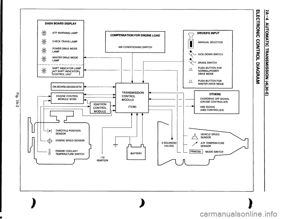
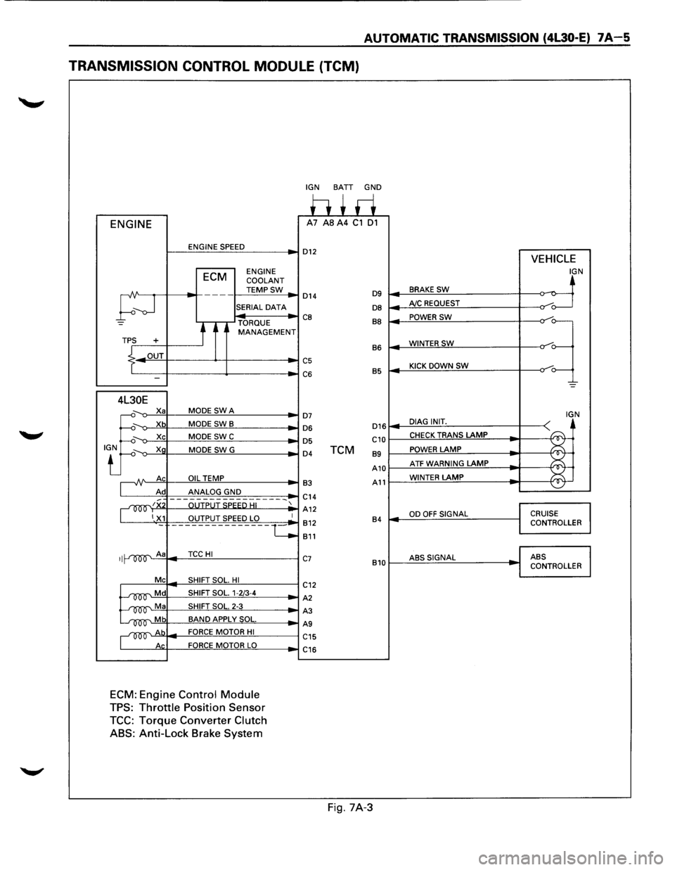
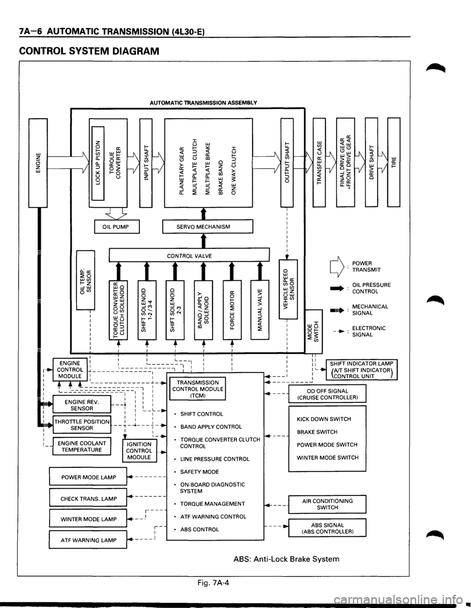
FUNCTIONS OF INPUT /OUTPUT COMPONENTS
Components Function
Speed sensor
Senses rotation
of output shaft and feeds the data to Transmission
(fixed
to transmission (T/M)) Control Module (TCM)
Throttle Senses the extent of throttle valve opening and the speed of the throttle
position sensor (TPS) valve lever motion to open the valve and feeds the data to TCM (fed to
(fixed to engine)
Engine Control Module (ECM) also)
I
Brake Switch (SW) Senses whether the driver has pressed the brake pedal or not and feeds
N (fixed
to brake pedal) the
information to TCM
p Kick-down SW (fixed to Senses whether the driver has pushed the accelerator pedal fully or not
u accelerator pedal) and feeds the information to TCM
T Mode
SW (fixed to T/M) Senses the select lever position and feeds the information to TCM
s Power drive SW Senses whether the driver has selected the power mode and feeds the
I (fixed to front console) information to TCM
G T/M
oil temp. sensor
Senses the T/M oil temperature and feeds the data to TCM
N Engine
coolant Senses the engine cooling water temperature and feeds the data to TCM
A temperature
SW (feeds the signal from ECM)
L
Engine speed
signal Feeds the signals monitoring engine speed to TCM from Ignition Control
Module
(fed to ECM also)
Air conditioning Senses whether the air conditioner has been switched on or not and
information feeds the information
to TCM
On-board diagnostic
input By monitoring the Ground (GND), the location of failure is shown on the
T/M
monitor lamp ("CHECK TRANS") by flashing the diagnostic trouble
code
Winter switch
Senses whether the driver has selected the winter mode, and feeds the
(fixed
to front console) information to TCM
Cruise
controller Downshift takes place when Overdrive OFF signal is received from auto
(Overdrive
OFF signal) cruise control unit
Shift
solenoid Selects shift point and gear position suited to the vehicle running con-s 1-2/3-4, 2-3
dition on the basis of TCM output 0 Band apply solenoid
Controls oil flow suited to the vehicle running condition on the basis of L
E TCM output
0 N
Torque
Converter Controls clutch engagement/disengagement suited to the vehicle
u 0 Clutch solenoid running condition on the basis of TCM output
T I Force motor Adjusts the oil pump delivery pressure to line pressure suited to the p D
(Pressure regulator vehicle running condition on the basis of TCM output u valve) T
Power drive mode lamp
Informs the driver whether the vehicle is in power mode or not
s Winter drive mode lamp Informs the driver whether the vehicle is in winter mode or not
I T/M monitor lamp Informs the driver of failure in the system. It also displays the self diagnosis
G
("CHECK TRANS") code.
N Data Link Connector
(DLC) When connected with TECH 1 or tester, can communicate the data for A
L function
check, etc. (fed to ECM also). When TECH 1 is not connected, can
communicate the
signal for torque management with ECM.
Self-diagnosis connector
When short-circuited with the bipolar connector, the T/M monitor lamp
displays
a failure by code.
ATF warning
lamp Lights when ATF oil temperature rises.
ABS signal When the select lever is at "Reverse" or "L" range, sends a signal to the
ABS controller as one of the ABS control conditions.
Page 885 of 1928
AUTOMATIC TRANSMISSION (4L30-E) 7A-13
NORMAL OPERATION OF 1994-95 4L30-E TRANSMISSION
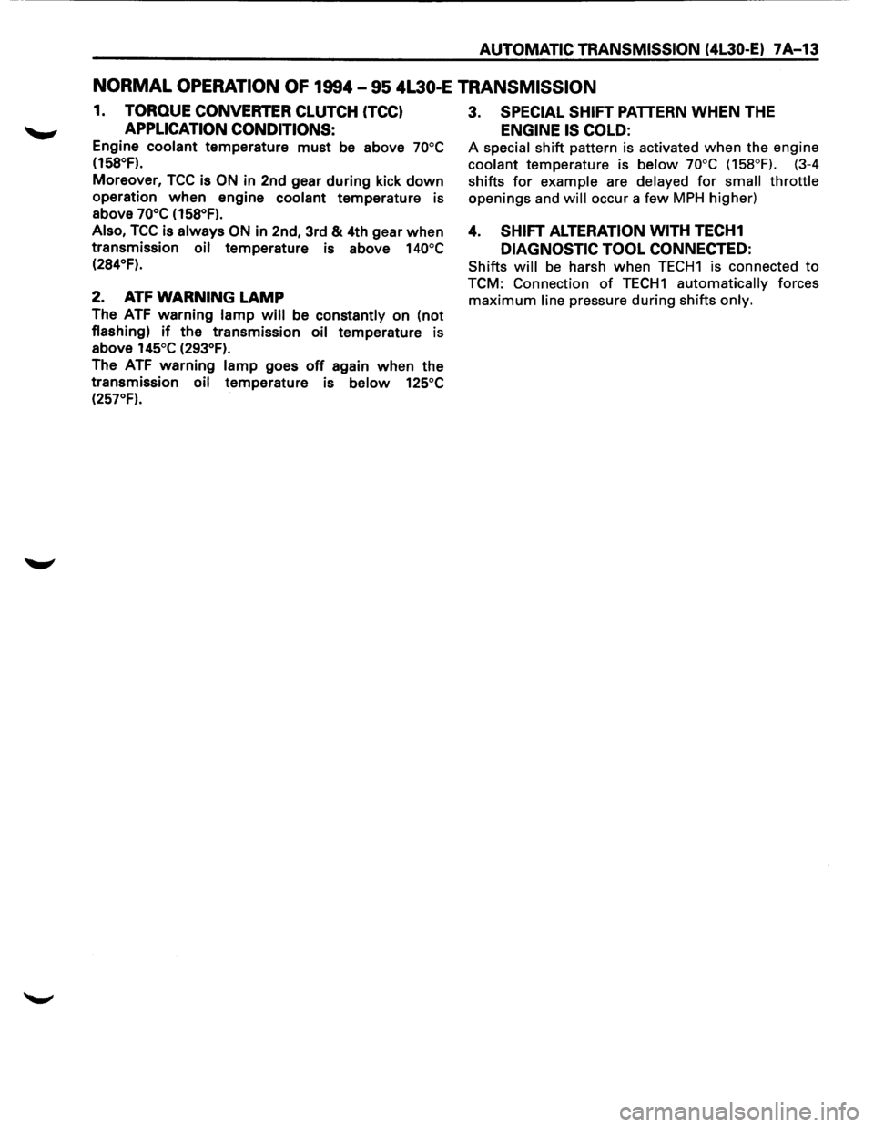
1. TORQUE CONVERTER CLUTCH (TCC)
APPLICATION CONDITIONS:
Engine coolant temperature must be above 70°C
(158°F).
Moreover, TCC is ON in 2nd gear during kick down
operation when engine coolant temperature is
above
70°C (158°F).
Also,
TCC is always ON in 2nd, 3rd & 4th gear when
transmission oil temperature is above 140°C
(284°F).
2. ATF WARNING LAMP
The ATF warning lamp will be constantly on (not
flashing) if the transmission oil temperature is
above
145°C (293°F).
The ATF warning lamp goes off again when the
transmission
oil temperature is below 125°C
(257°F).
3. SPECIAL SHIFT PATTERN WHEN THE
ENGINE IS COLD:
A special shift pattern is activated when the engine
coolant temperature is below 70°C (158°F). (3-4
shifts
for example are delayed for small throttle
openings and will occur a few MPH higher)
4. SHIFT ALTERATION WITH TECH1
DIAGNOSTIC TOOL CONNECTED:
Shifts will be harsh when TECH1 is connected to
TCM: Connection of TECH1 automatically forces
maximum line pressure during shifts only.
Page 913 of 1928
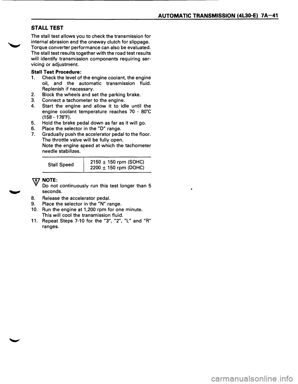
STALL TEST
The stall test allows you to check the transmission for
internal abrasion and the oneway clutch for slippage.
Torque converter performance can also be evaluated.
The
stall test results together with the road test results
will identify transmission components requiring ser
vicing or adjustment.
Stall Test Procedure:
1. Check the level of the engine coolant, the engine
oil, and the automatic transmission fluid.
Replenish
if necessary.
2. Block the wheels and set the parking brake.
3. Connect a tachometer to the engine.
4. Start the engine and allow it to idle until the
engine coolant temperature reaches
70 -8o·c
(158 -176.F).
5. Hold the brake pedal down as far as it will go.
6. Place the selector in the "D" range.
7. Gradually push the accelerator pedal to the floor.
The throttle valve
will be fully open.
Note the engine speed at which the tachometer
needle stabilizes.
Stall Speed
\fl NOTE:
2150 ± 150 rpm (SOHC)
2200 ± 150 rpm (DOHC)
VI Do not continuously run this test longer than 5
........, seconds.
8. Release the accelerator pedal.
9. Place the selector in the "N" range.
10. Run the engine at 1,200 rpm for one minute.
This
will cool the transmission fluid.
11. Repeat Steps 7-10 for the "3", "2", "L" and "R"
ranges.
AUTOMATIC TRANSMISSION (4L30-E) 7A-41