ISUZU TROOPER 1995 Workshop Manual
Manufacturer: ISUZU, Model Year: 1995, Model line: TROOPER, Model: ISUZU TROOPER 1995Pages: 1928
Page 1201 of 1928
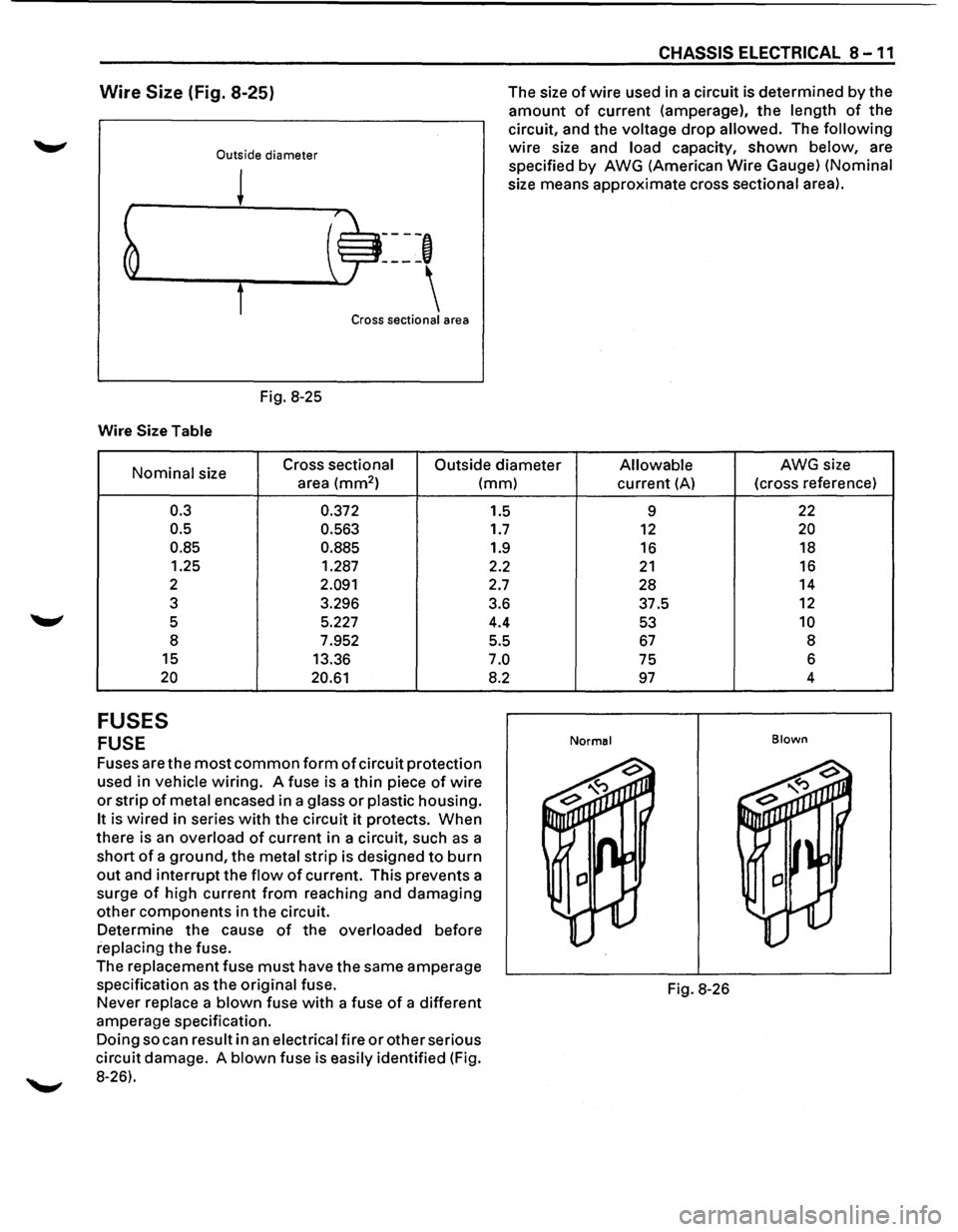
Wire Size (Fig. 8-25)
Outside diameter
Fig. 8-25
Wire Size Table
----,
Cross sectional area
CHASSIS ELECTRICAL 8 -11
The size of wire used in a circuit is determined by the
amount of current (amperage), the length of the
circuit, and the voltage drop allowed. The following
wire size and load capacity, shown below, are
specified
by AWG (American Wire Gauge) (Nominal
size means approximate cross sectional area).
Nominal size Cross sectional
Outside diameter Allowable AWG size
area
(mm2 ) (mm)
0.3
0.5
0.85
1.25
2
3
5 8
15
20
FUSES
FUSE
0.372
0.563
0.885
1.287
2.091
3.296
5.227
7.952
13.36
20.61
Fuses are the most common form of circuit protection
used in vehicle wiring. A fuse is a thin piece of wire
or strip of metal encased in a glass or plastic housing.
It is wired in series with the circuit it protects. When
there is an overload of current in a circuit, such as a
short of a ground, the metal strip is designed to burn
out and interrupt the flow of current. This prevents a
surge
of high current from reaching and damaging
other components in the circuit.
Determine the cause of the overloaded before
replacing the fuse.
The
replacement fuse must have the same amperage
specification as the original fuse.
Never replace a blown fuse with a fuse of a different
amperage specification.
Doing so can result in an electrical fire or other serious
circuit damage. A blown fuse is easily identified (Fig.
8-26). 1.5
1.7
1.9
2.2
2.7
3.6 4.4
5.5
7.0
8.2
current (A) (cross
reference)
9
22
12 20
16 18
21 16
28 14
37.5
12
53 10
67 8
75 6
97 4
Normal Blown
Fig.
8-26
Page 1202 of 1928
8-12 CHASSIS ELECTRICAL
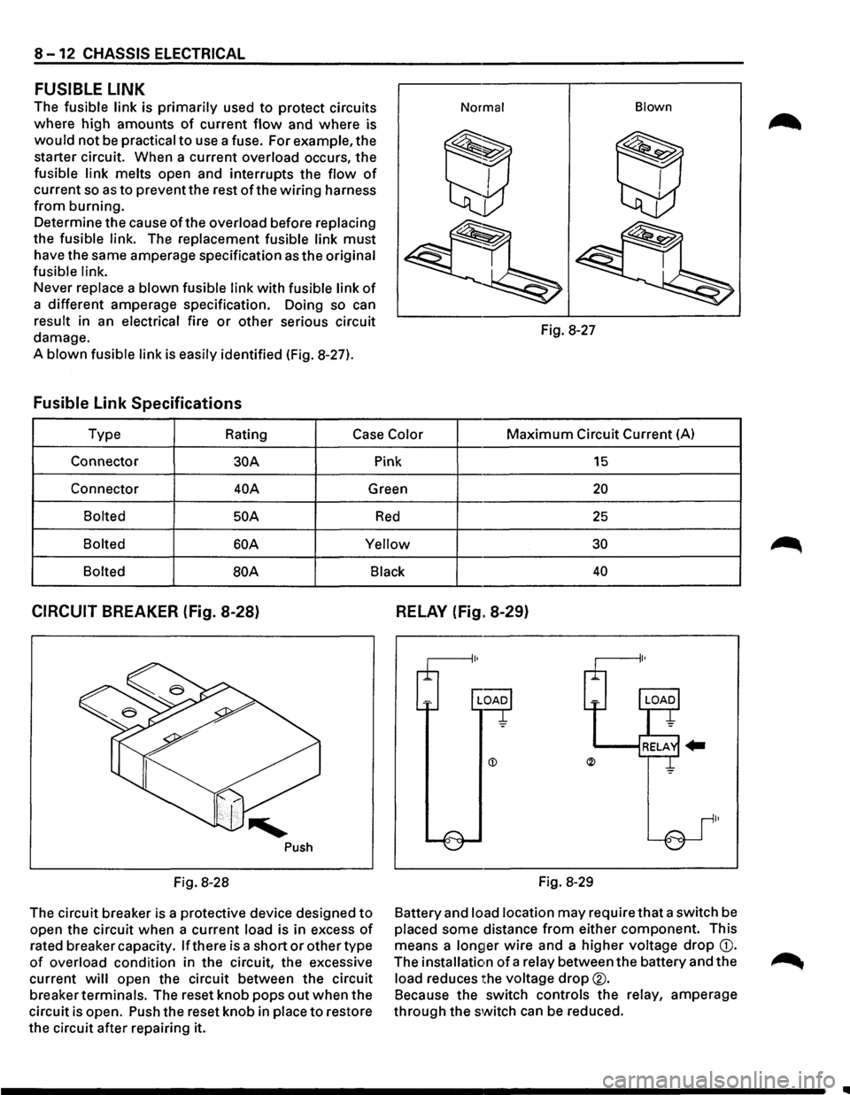
FUSIBLE LINK
The fusible link is primarily used to protect circuits
where high amounts
of current flow and where is
would not be practical to use a fuse. For example, the
starter circuit. When a current
overload occurs, the
fusible link melts open and interrupts the flow of
current so as to prevent the rest of the wiring harness
from burning.
Determine the cause
ofthe overload before replacing
the fusible link. The replacement fusible link must
have the same amperage specification as the original
fusible link.
Never replace a blown fusible link with fusible link of
a different amperage specification. Doing so can
result in an electrical fire or other serious circuit
damage.
A
blown fusible link is easily identified (Fig. 8-27).
Fusible Link Specifications
Normal Blown
Fig.
8-27
Type Rating
Case Color Maximum Circuit Current (A)
Connector
30A Pink 15
Connector 40A Green 20
Bolted 50 A Red 25
Bolted 60A Yellow 30
Bolted
BOA Black 40
CIRCUIT BREAKER (Fig. 8-28)
Push
Fig. 8-28
The circuit breaker is a protective device designed
to
open the circuit when a current load is in excess of
rated breaker capacity. If there is a short or other type
of overload condition in the circuit, the excessive
current
will open the circuit between the circuit
breaker
terminals. The reset knob pops out when the
circuit is open. Push the reset knob in
place to restore
the circuit after repairing it.
RELAY (Fig. 8-29)
Fig. 8-29
Battery and
load location may require that a switch be
placed some distance from either component. This
means a
longer wire and a higher voltage drop G).
The installation of a relay between the battery and the
load reduces the voltage drop®.
Because the switch controls the relay, amperage
through the switch can be reduced.
..
Page 1203 of 1928
CHASSIS ELECTRICAL 8-13
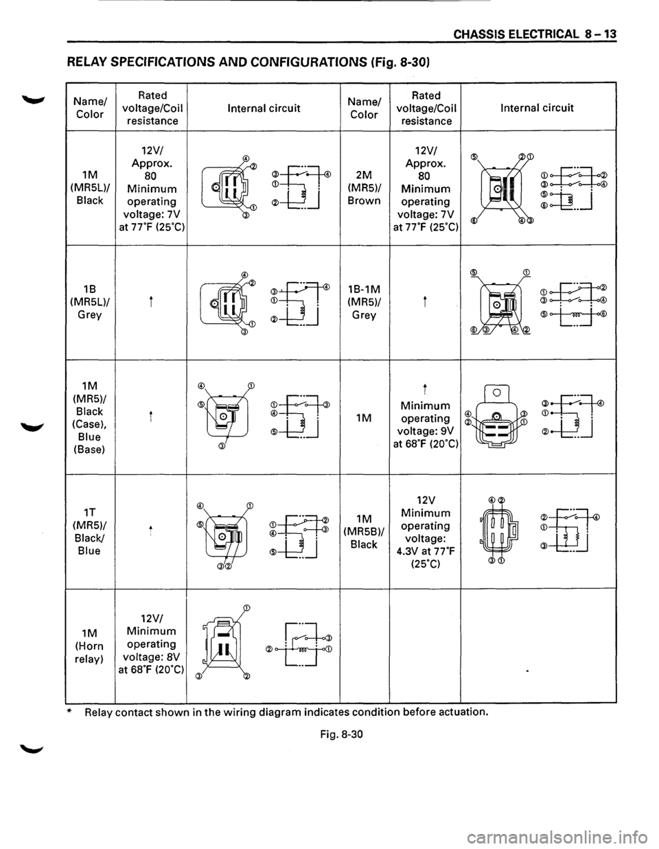
RELAY SPECIFICATIONS AND CONFIGURATIONS (Fig. 8-30)
Name/ Rated Name/ Rated
Color voltage/Coil
Internal circuit Color voltage/Coil Internal circuit
resistance resistance
12V/ 12V/
® ~1 Approx.
~
®u~
Approx.
~£:=!:~ 1M 80 2M 80
a(( (MRSL)/ Minimum
operating ® ... J Brown operating ::Q __ j
voltage: 7V voltage: 7V ® 4 at 77°F (2S°C) at 77"F (2SOC)
~
®
®tiT
18-1M
•
:E:t:
(MR5)/ i @ . . @
Grey Grey ®~ 4
1M
:@ff
i
®~
(MRS)/
rou~ Minimum
u~ Black i 0 @ . 1M operating ~ : 4
(Case), ® ... J ® 1
® J Blue voltage:
9V
(Base) @ at 68°F (20°C)
:@j
12V @®
1T
m
1M Minimum
'
m~
(MRS)/ t (MRSB)/ operating ~ : Black/ ' 0 @ voltage: @ u
Blue ® 4.3V at 77°F
@® (2SOC)
1
12V/
1@ .ff
1M Minimum
(Horn operating ®
at 68°F (20°C) @ .
* Relay contact shown in the wiring diagram indicates condition before actuation.
Fig.
8-30
Page 1204 of 1928
8-14 CHASSIS ELECTRICAL
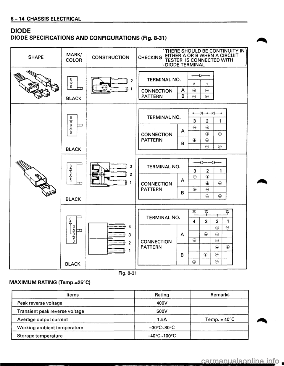
DIODE
DIODE SPECIFICATIONS AND CONFIGURATIONS (Fig. 8-31)
MARK/ [THERE SHOULD BE CONTINUITY IN l
SHAPE
CONSTRUCTION CHECKING EITHER A OR B WHEN A CIRCUIT
COLOR TESTER IS CONNECTED WITH
DIODE TERMINAL
~ [1r!Bf=5~
o--j)f--o
TERMINAL NO. 2 1
CONNECTION A @ e I PATTERN B e ~ BLACK I i !
[}
o------J>f----o TERMINAL
NO.
3 2 1
e ~ A c±l 8 CONNECTION
PATTERN B c±l e
BLACK e c±l
[
!i~~
~ u 3 TERMINAL NO.
3 2 1
pJr-qr u 2 e c±l I n 1 A CONNECTION c±l 8
~
PATTERN c±l e B (f) BLACK (~
2f 2f 2f
[i
TERMiiNAL NO. 4 3 2 1
·-·-·-·fl-4 c±l e
·-·-·-·#-3
A e c±l -·-· t=:-e c±l ·-·-·-·#-2 CONNECTION
PATTERN 8 ~ ·-·-·-·#-1
B l±l e I
BLACK I c±l e
Fig. 8-31
MAXIMUM RATING (Temp.:25°C)
Items Rating Remarks
Peak reverse
voltage 400V
Transient peak reverse voltage 500V
Average output current 1.!5A Temp.= 40°C
Working ambient temperature -30°C-aooc
Storage temperature -40°C·-1 oooc
..
Page 1205 of 1928
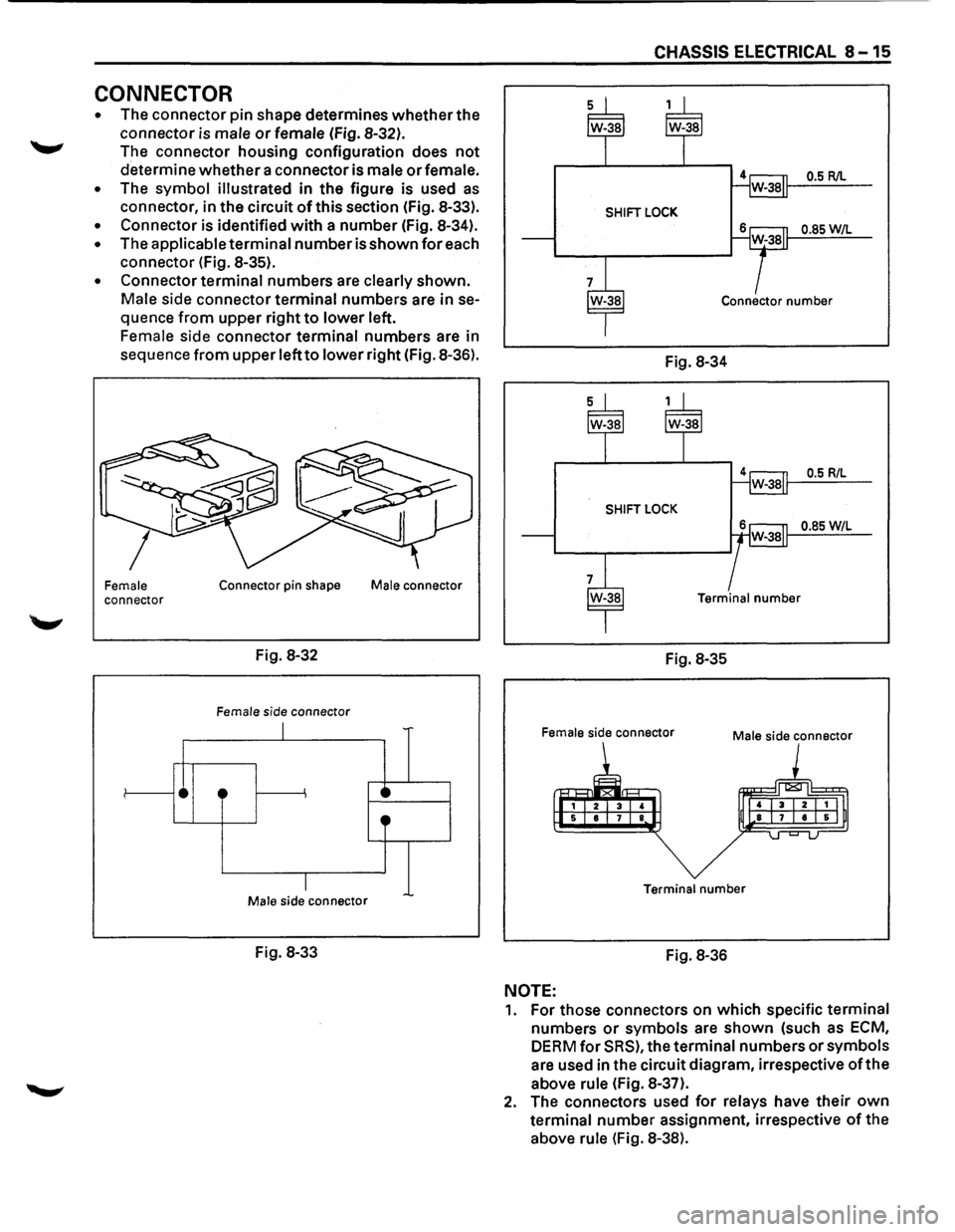
CONNECTOR
• The connector pin shape determines whether the
connector is
male or female (Fig. 8-32).
The connector housing configuration does
not
determine whether a connector is male or female.
• The symbol illustrated in the figure is used as
connector, in the circuit of this section (Fig. 8-33).
• Connector is identified with a number (Fig. 8-34).
• The applicable terminal number is shown for each
connector (Fig. 8-35).
• Connector terminal numbers are clearly shown.
Male side connector terminal numbers are in se
quence
from upper right to lower left.
Female side connector terminal numbers are in
sequence
from upper left to lower right (Fig. 8-36).
Female connector
•
Connector pin shape
Fig. 8-32
Female side connector
I
·~
I Male s1de connector
Fig. 8-33
Male connector
·~ 0
CHASSIS ELECTRICAL 8-15
0.5 R/L
SHIFT LOCK
0.85W/L
Connector number
Fig. 8-34
0.5 R/L
SHIFT LOCK
0.85 W/L
Terminal number
Fig. 8-35
Female side connector Male side connector
Terminal number
Fig. 8-36
NOTE:
1. For those connectors on which specific terminal
numbers
or symbols are shown (such as ECM,
DERM for SRS), the terminal numbers or symbols
are used in the circuit diagram, irrespective
of the
above rule (Fig. 8-37).
2. The connectors used for relays have their own
terminal number assignment, irrespective of the
above
rule (Fig. 8-38).
Page 1206 of 1928
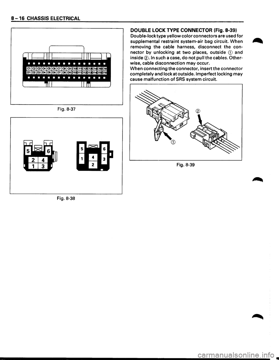
8 -16 CHASSIS ELECTRICAL
Fig. 8-37
Fig. 8-38
DOUBLE LOCK TYPE CONNECTOR (fig. 8-39)
Double-lock type yellow color connectors are used for
supplemental restraint system-air bag circuit. When ...
removing the cable harness, disconnect the con-
nector
by unlocking at two places, outside CD and
inside
®.In such a case, do not pull the cables. Other-
wise, cable disconnection may occur.
When connecting the connector, insert the connector
completely and lock at outside. Imperfect locking may
cause malfunction of SRS system circuit.
Fig. 8-39
•
Page 1207 of 1928
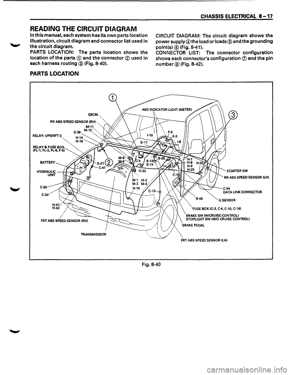
READING THE CIRCUIT DIAGRAM
In this manual, each system has its own parts location
illustration,
circuit diagram and connector list used in
the circuit diagram.
PARTS LOCATION: The parts location shows the
location of the parts CD and the connector® used in
each harness routing ® (fig. 8-40).
PARTS LOCATION
EBCM-,
RR ABS SPEED SENSOR (RHI "',~ M-11 ,,
C-39 M-12~'-, RELAY: UPSHIFT-2 ~
CHASSIS ELECTRICAL 8-17
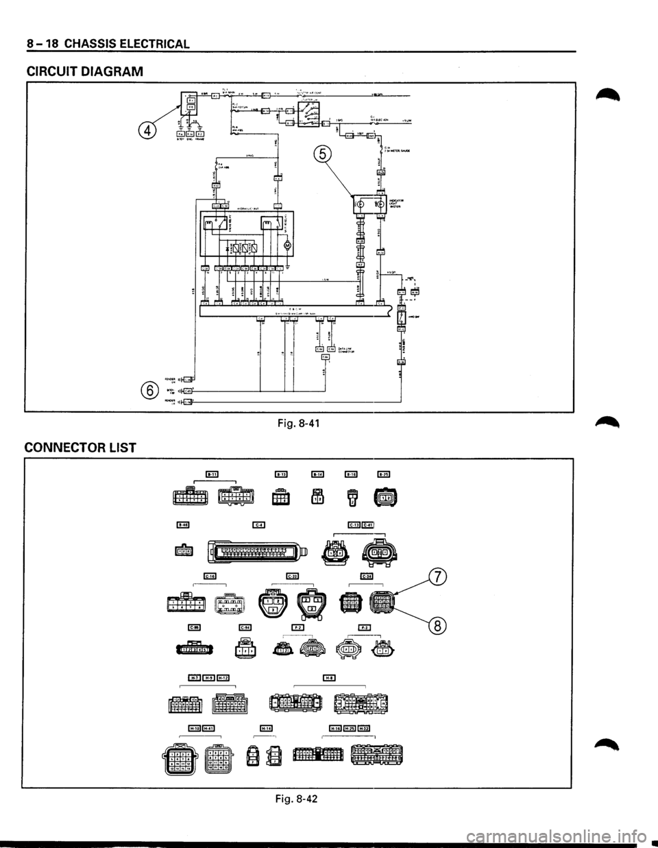
CIRCUIT DIAGRAM: The circuit diagram shows the
powersupply@the load or loads® and the grounding
point(s)
® (Fig. 8-41 ).
CONNECTOR LIST: The connector configuration
shows
each connector's configuration (J) and the pin
number® (Fig. 8-42).
RELAY & FUSE BO~"'
7
~<-:;;;:~:~:_::0:;;::::'=l-\,.-..:._::::;;,...6
IFL-1, FL-2, FL-6, F-91 , "" ;;~~~~~~~;g~~k~
C-33
C-34
Fig. 8-40
STARTERSW
RR ABS SPEED SENSOR ILHI
C-94 DATA LINK CONNECTOR
GSENSOR
FUSE BOX IC-3, C-4, C-10, C-141
BRAKE SW IW/CRUISE CONTROL! STOPLIGHT SW (W/0 CRUISE CONTROL!
FRT ABS SPEED SENSOR ILHI
Page 1208 of 1928
8 -18 CHASSIS ELECTRICAL
CIRCUIT DIAGRAM
opllM!
4
® ·:; ::flli:~j}-o: ------'-__J_'----'
~~ •11-E~··•;Jf'-' -----------------'
CONNECTOR LIST
Fig. 8-41
lEI [E] lmiEill -,
~ ,, ••
-
~ '''' ''
•
. ' .
Cl1ll;1 ~ ·~~~~·11Lt1• ~
i ~ hl:i.~.mmn IIIII
Fig. 8-42
•
Page 1209 of 1928
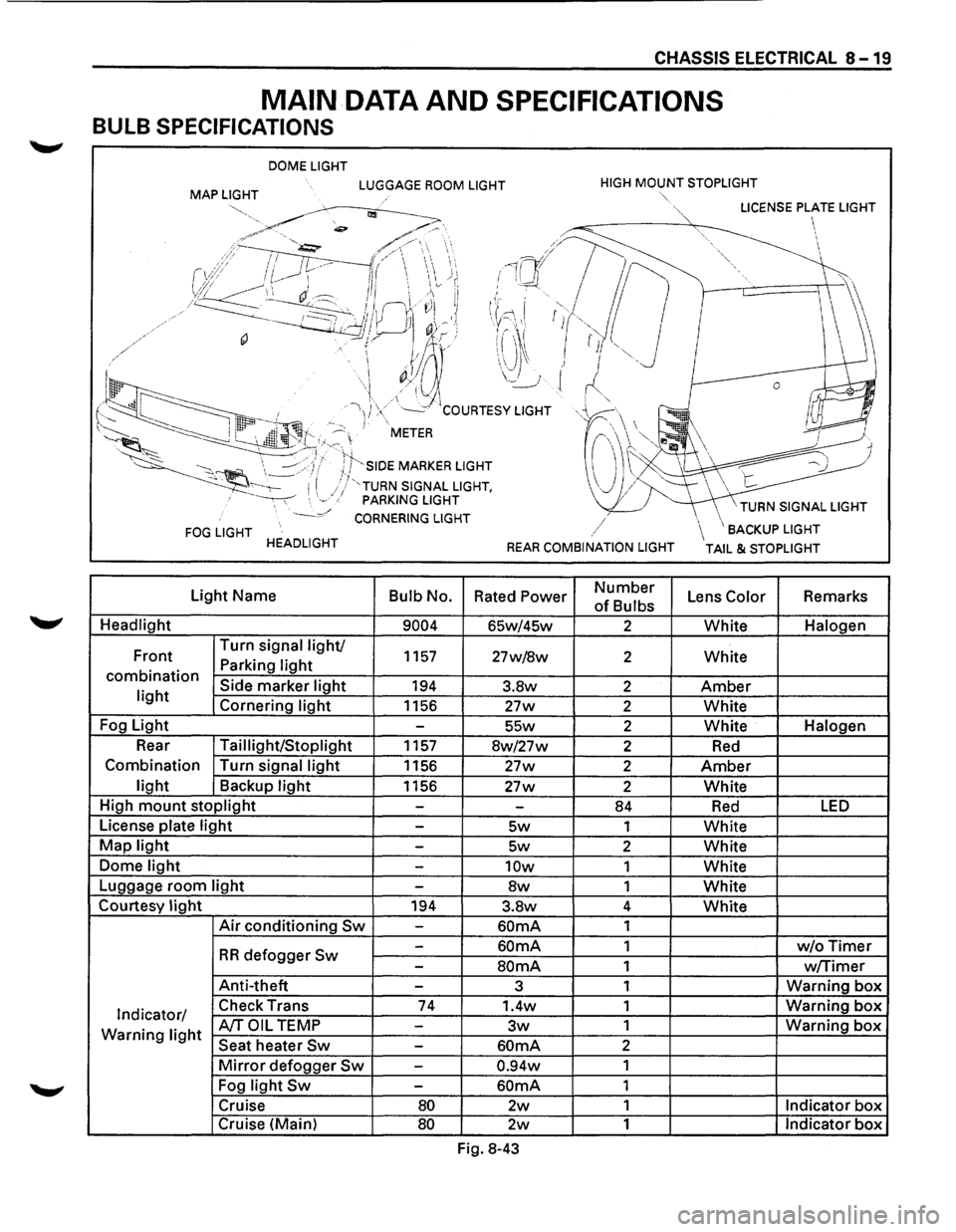
CHASSIS ELECTRICAL 8-19
MAIN DATA AND SPECIFICATIONS
BULB SPECIFICATIONS
DOME LIGHT
MAP LIGHT LUGGAGE ROOM LIGHT HIGH MOUNT STOPLIGHT
FOG LIGHT HEADLIGHT
Light Name
Bulb No.
Headlight
9004
Front Turn
signal light/ 1157 Parking light combination Side marker light 194 light Cornering light 1156
Fog Light
-
Rear Taillight/Stoplight 1157
Combination Turn signal
light 1156
light Backup light 1156
High
mount stoplight -
License plate light -
Map light -
Dome light -
Luggage room light -
Courtesy light 194
Air conditioning Sw -
-
RR defogger Sw -
Anti-theft -
Indicator/ Check
Trans 74
Warning light A/TOIL TEMP -
Seat heater Sw -
Mirror defogger Sw -
Fog light Sw -
Cruise 80
Cruise (Main) 80
""·
,/
REAR COMBINATION LIGHT
Rated Power Number
of Bulbs
65w/45w 2
27w/8w 2
3.8w 2
27w 2
55w 2
8w/27w 2
27w 2
27w 2
-84
5w 1
5w 2
10w 1
8w 1
3.8w 4
60mA 1
60mA 1
SOmA 1
3 1
1.4w 1
3w 1
60mA 2
0.94w 1
60mA 1
2w 1
2w 1
Fig. 8-43
\BACKUP LIGHT
TAIL & STOPLIGHT
Lens Color Remarks
White Halogen
White
Amber
White
White Halogen
Red
Amber
White
Red LED
White
White
White
White
White
w/oTimer
w/Timer
Warning box
Warning box
Warning box
Indicator box
Indicator box
Page 1210 of 1928
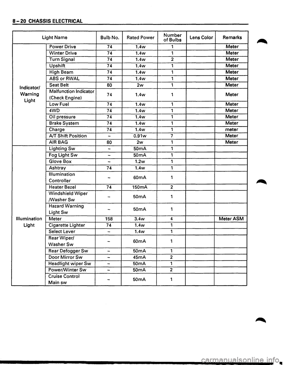
8-20 CHASSIS ELECTRICAL
Light Name Bulb No. Rated Power Number Lens Color Remarks of Bulbs
Power Drive 74 1.4w 1
Meter
Winter Drive 74 1.4w
1 Meter
Turn Signal 74 1.4w 2 Meter
Upshift
74 1.4w 1 Meter
High Beam
74 1.4w 1 Meter
ABSorRWAL 74 1.4w 1 Meter
Indicator/ Seat Belt 80 2w 1 Meter
Warning Malfunction Indicator 74 1.4w
1 Meter
Light (Check
Engine)
Low Fuel 74 1.4w 1 Meter
4WD
74 1.4w 1 Meter
Oil pressure 74 1.4w 1 Meter
Brake System 74 1.4w 1 Meter
Charge 74 1.4w 1
meter
A/T Shift Position -0.91w 7 Meter
AIR BAG 80 2w 1 Meter
Lighting Sw -SOmA 1
Fog Light
Sw -SOmA 1
Glove Box -1.2w 1
Ashtray
74 1.4w 1
Illumination
60mA 1 -Controller
Heater Bezel 74 1SOmA 2
Windshield
Wiper SOmA 1 -/WasherSw
Hazard Warning SOmA 1 -Light Sw
Illumination Meter 158 3.4w 4 MeterASM
Light
Cigarette Lighter
74 1.4w
1
Select Lever -1.4w 1
Rear
Wiper/ 60mA 1 -WasherSw
Rear Defogger Sw -SOmA 1
Door
Mirror Sw -45mA 2
Headlight
wiper Sw -SOmA 1
Power/Winter
Sw -SOmA 2
Cruise Control
SOmA 1 -Main sw
II