ISUZU TROOPER 1995 Workshop Manual
Manufacturer: ISUZU, Model Year: 1995, Model line: TROOPER, Model: ISUZU TROOPER 1995Pages: 1928
Page 1191 of 1928

CHASSIS ELECTRICAL 8-1
·SECTION 8
CHASSIS ELECTRICAL
'\f CAUTION: .
When fasteners are removed, always reinstall them at the same location from which they were removed.
If a fastener needs to be replaced, use the correct part number fastener for that application. If the correct
part number fastener is not
available, a fastener of equal size and strength (or stronger) may be used.
Fasteners that are not reused, and those requiring thread
locking compound, will be called out. The correct
torque
values must be used when installing fasteners that require it. If the above conditions are not
followed, parts or system damage could result.
CONTENTS
General Information .................................... 8-2
Notes for Working on Electrical
Items .................................................... 8-2
Symbols and Abbreviations ................. 8-8
Symbols ............................................ 8-8
Abbreviations ................................... 8-9
Parts for Electrical Circuit ..................... 8-10
Wiring ............................................... 8-10
Fuse .................................................. 8-11
Fusible Link ....................................... 8-12
Circuit Breaker ................................... 8-12
Relay ................................................. 8-12
Relay Specifications and
Configurations ................................ 8-13
Diode ................................................. 8-14
Connector ......................................... 8-15
Reading the Circuit Diagram ................ 8-17
Main Data and Specifications .................... 8-19
Bulb Specifications ................................ 8-19
Fuse,
Fusible Link and
Circuit Breaker Location ..................... 8-21
Fuse
Block Circuit .................................. 8-22
Reference Table of Fuse, Fusible
Link and Circuit Breaker ..................... 8-23
Relay Location ....................................... 8-27
Diode Location .......................................
8-28
Grounding Point .................................... 8-29
Reference Table ................................ 8-29
Location ............................................ 8-31
Cable Harness Routing .......................... 8-34
System Repair .............................................. 8-38
Start and Charging ................................ 8-38
Engine Control Module
(ECM) ................................................... 8-47
Headlight and Fog Light ........................ 8-58
Front Side Marker Light, Parking Light,
Taillight, License Plate Light and
Illumination Light .............................. 8-76
Stoplight and Rear Defogger .............. 8-92
Turn Signal Light, Hazard
Warning
Light, Cornering Light,
Backup
Light and Horn ..................... 8-106
Dome Light, Luggage room Light,
Courtesy Light, Map Light,
Seat Belt Switch and
Warning Buzzer ................................. 8-128
Power Door Lock ................................. 8-142
Power
Window .................................... 8-156
Cruise
Control ...................................... 8-172
Anti-Lock Brake
System (ABS) ........... 8-178
Rear
Wheel Anti-Lock Brake
System (RWAL) ................................. 8-185
Transmission
Control Module
(TCM) ................................................. 8-192
A/T Shift Lock ...................................... 8-200
Windshield
Wiper/Washer and
Rear
Wiper/Washer .......................... 8-205
Headlight wiper /washer ..................... 8-232
Audio, Auto Antenna,
Cigarette
Lighter and digital clock ... 8-246
Power Door Mirror ............................... 8-254
Anti-theft System ................................ 8-270
Meter and Warning/Indicator Light ... 8-288
A/T Shift Indicator ............................... 8-336
Heater and
Air Conditioning ............... 8-340
Sun
Roof ............................................... 8-346
Power Seat ........................................... 8-360
Seat
Heater .......................................... 8-37 4
Supplemental Restraint
System (SRS) -AIR BAG ................... 8-382
Page 1192 of 1928
-·*; ~---
8-2 CHASSIS ELECTRICAL
GENERAL INFORMATION
The chassis electrical system is of 12-volt specifications with a negative ground polarity.
Wire sizes are appropriate
to respective circuits, and classified by color. (The classification of harnesses by
color is shown on the circuit diagram for ease of harness identification.)
The
wire size is determined by load capacity and the length of wire required.
The
vehicle harnesses are: body harness, chassis harness, engine room harness, instrument harness,
transmission harness, engine
ECGI harness, dome light harness, door harness, rear body harness, tailgate
harness,
SRS harness and battery cables.
The harnesses are protected either
by tape or corrugated tube, depending on harness location.
The circuit
for each system consists of the power source, wire, fuse, relay, switch, load parts and ground, all of
which are shown on the circuit diagram.
In this manual, each electrical device is classified by system. For major parts shown on the circuit based on
the circuit diagram
for each system, a summary, diagnosis oftroubles, inspection and removal and installation
procedures are detailed.
NOTES FOR WORKING ON ELECTRICAL ITEMS
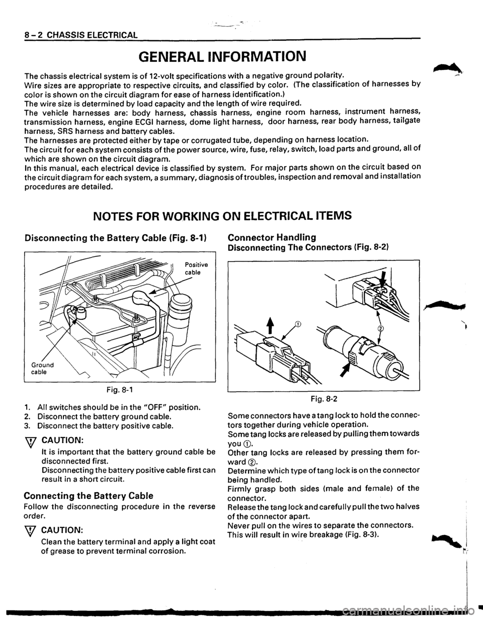
Disconnecting the Battery Cable (Fig. 8-1)
Ground cable
Fig. 8-1
1. All switches should be in the "OFF" position.
2. Disconnect the battery ground cable.
3. Disconnect the battery positive cable.
W CAUTION:
It is important that the battery ground cable be
disconnected first.
Disconnecting the battery positive cable first can
result in a short circuit.
Connecting the Battery Cable
Follow the disconnecting procedure in the reverse
order.
\V CAUTION:
Clean the battery terminal and apply a light coat
of grease to prevent terminal corrosion.
Connector Handling
Disconnecting The Connectors (Fig. 8-2)
Fig. 8-2
Some connectors have a tang lock to hold the connec
tors together during vehicle operation.
Some tang locks are released by pulling them towards
you
G).
Other tang locks are released by pressing them for
ward®.
Determine which type oftang lock is on the connector
being handled.
Firmly grasp both sides (male and female)
of the
connector. Release the tang lock and carefully pull the
two halves
of the connector apart.
Never pull on the wires
to separate the connectors.
This
will result in wire breakage (Fig. 8-3).
.,
..
Page 1193 of 1928
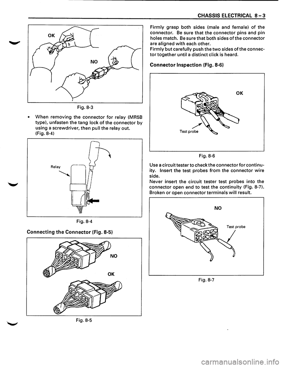
Fig. 8-3
• When removing the connector for relay (MR5B
type), unfasten the tang
lock of the connector by
using a screwdriver, then pull the relay out.
(Fig. 8-4)
Relay
~
Fig. 8-4
Connecting the Connector (Fig. 8-5)
Fig. 8-5
CHASSIS ELECTRICAL 8-3
Firmly grasp both sides (male and female) of the
connector.
Be sure that the connector pins and pin
holes match. Be sure that both sides of the connector
are
aligned with each other.
Firmly but carefully push the two sides of the connec
tor together until a distinct click is heard.
Connector Inspection (Fig. 8-6)
OK
Test probe
Fig. 8-6
Use a circuit tester to check the connector for continu
ity.
Insert the test probes from the connector wire
side. Never insert the circuit tester test probes into the
connector open end
to test the continuity (Fig. 8-7).
Broken
or open connector terminals will result.
NO
Fig. 8-7
Page 1194 of 1928
8-4 CHASSIS ELECTRICAL
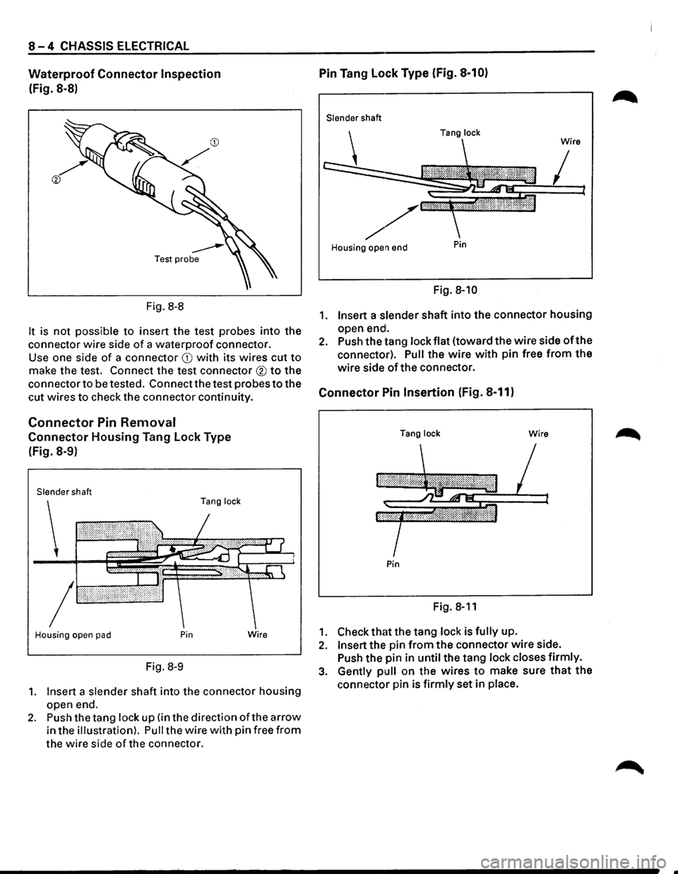
Waterproof Connector Inspection
(Fig. 8-8)
Fig.
8-8
It is not possible to insert the test probes into the
connector wire side
of a waterproof connector.
Use one side
of a connector CD with its wires cut to
make the test. Connect the test connector ® to the
connector
to be tested. Connect the test probes to the
cut wires
to check the connector continuity.
Connector Pin Removal
Connector Housing Tang Lock Type
(Fig. 8-9)
Slender shaft
Tang lock
Housing open pad Pin
Fig. 8-9
Wire
1. Insert a slender shaft into the connector housing
open end.
2. Push the tang lock up (in the direction ofthe arrow
in the illustration). Pull the wire with pin free from
the wire side of the connector.
Pin Tang Lock Type (Fig. 8-10)
Slender shaft
Housing open end
Pin
Fig. 8-10
1. Insert a slender shaft into the connector housing
open
endl.
2. Push the tang lock flat (toward the wire side oft he
connector).
Pull the wire with pin free from the
wire side of the connector.
Connector Pin Insertion (Fig. 8-11)
Tang lock Wire
Pin
Fig. 8-11
1. Check that the tang lock is fully up.
2. Insert the pin from the connector wire side.
Push the pin in
until the tang lock closes firmly.
3. Gently pull on the wires to make sure that the
connector pin is firmly set in place.
Page 1195 of 1928
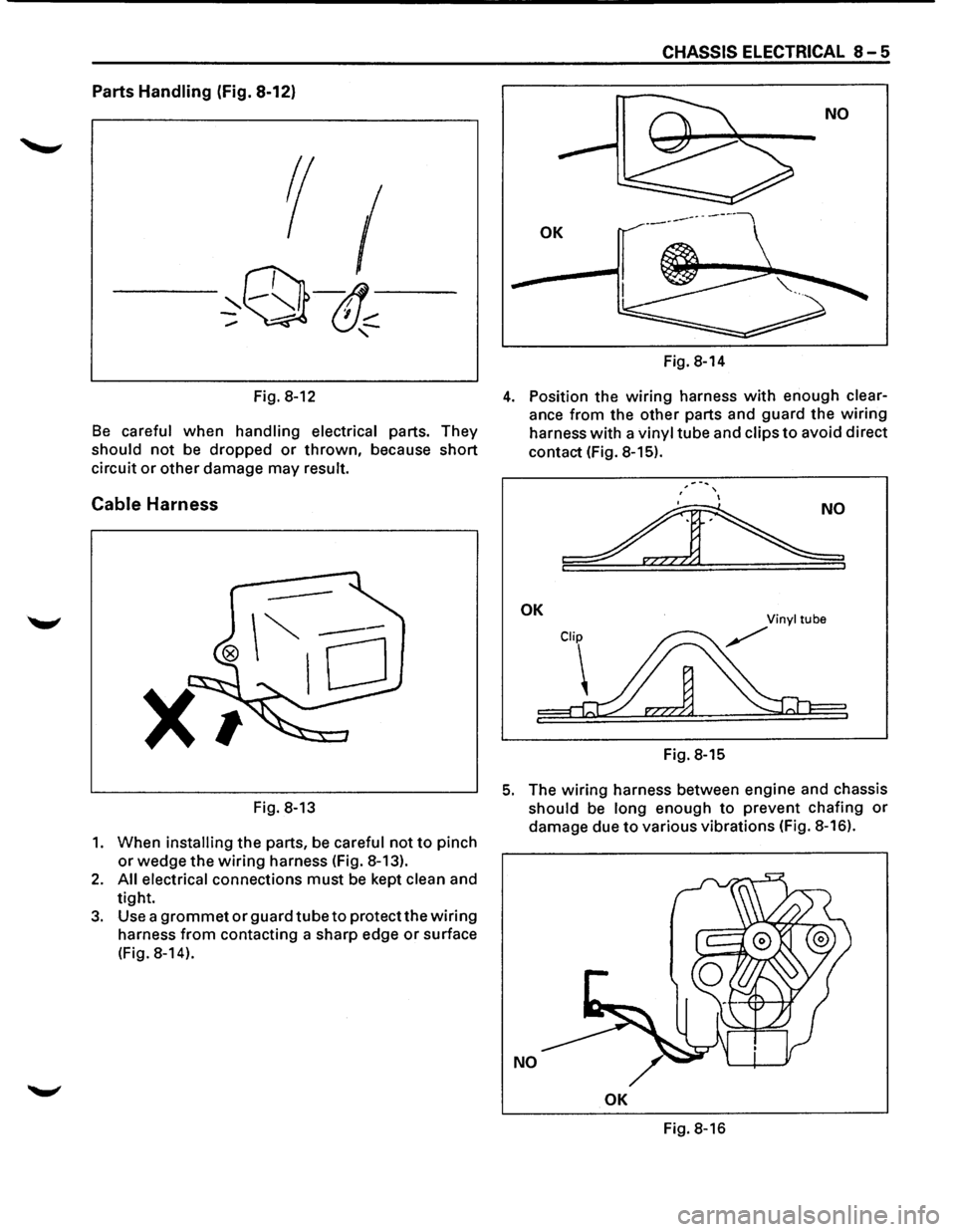
Parts Handling (Fig. 8-12)
Fig. 8-12
Be careful when handling electrical parts. They
should
not be dropped or thrown, because short
circuit
or other damage may result.
Cable Harness
--
Xt
Fig. 8-13
1. When installing the parts, be careful not to pinch
or wedge the wiring harness (Fig. 8-13).
2. All electrical connections must be kept clean and
tight.
3. Use a grommet orguardtubeto protect the wiring
harness from contacting a sharp edge or surface
(Fig.
8-14).
CHASSIS ELECTRICAL 8-5
Fig. 8-14
4. Position the wiring harness with enough clear
ance from the other parts and guard the wiring
harness with a vinyl tube and clips to avoid direct
contact (Fig.
8-15).
', '
~
OK
Fig. 8-15
5. The wiring harness between engine and chassis
should be long enough
to prevent chafing or
damage due to various vibrations (Fig. 8-16).
NO
OK
Fig. 8-16
Page 1196 of 1928
8-6 CHASSIS ELECTRICAL
SPLICING WIRE
1. Open the Harness
If the harness is taped, remove the tape. To avoid wire
insulation damage, use a sewing "seam ripper"
{available from sewing supply stores) to cut open the
harness.
If the harness has a black plastic conduit, simply pull
out the desired wire.
2. Cut the wire
Begin by cutting as little wire off the harness as
possible. You
may need the extra length of wire later
if you decide to cut more wire off to change the
location
of a splice. You may have to adjust splice
locations
to make certain that each splice is at least
1-1/2" {40 mm) away from other splices, harness
branches,
or connectors.
3. Strip the insulation
When replacing a wire, use a wire of the same size as
the original wire. Check the stripped wire for nicks or
cut stands. If the wire is damaged, repeat the proce
dure on a new section of wire. The two stripped wire
ends should be equal in length.
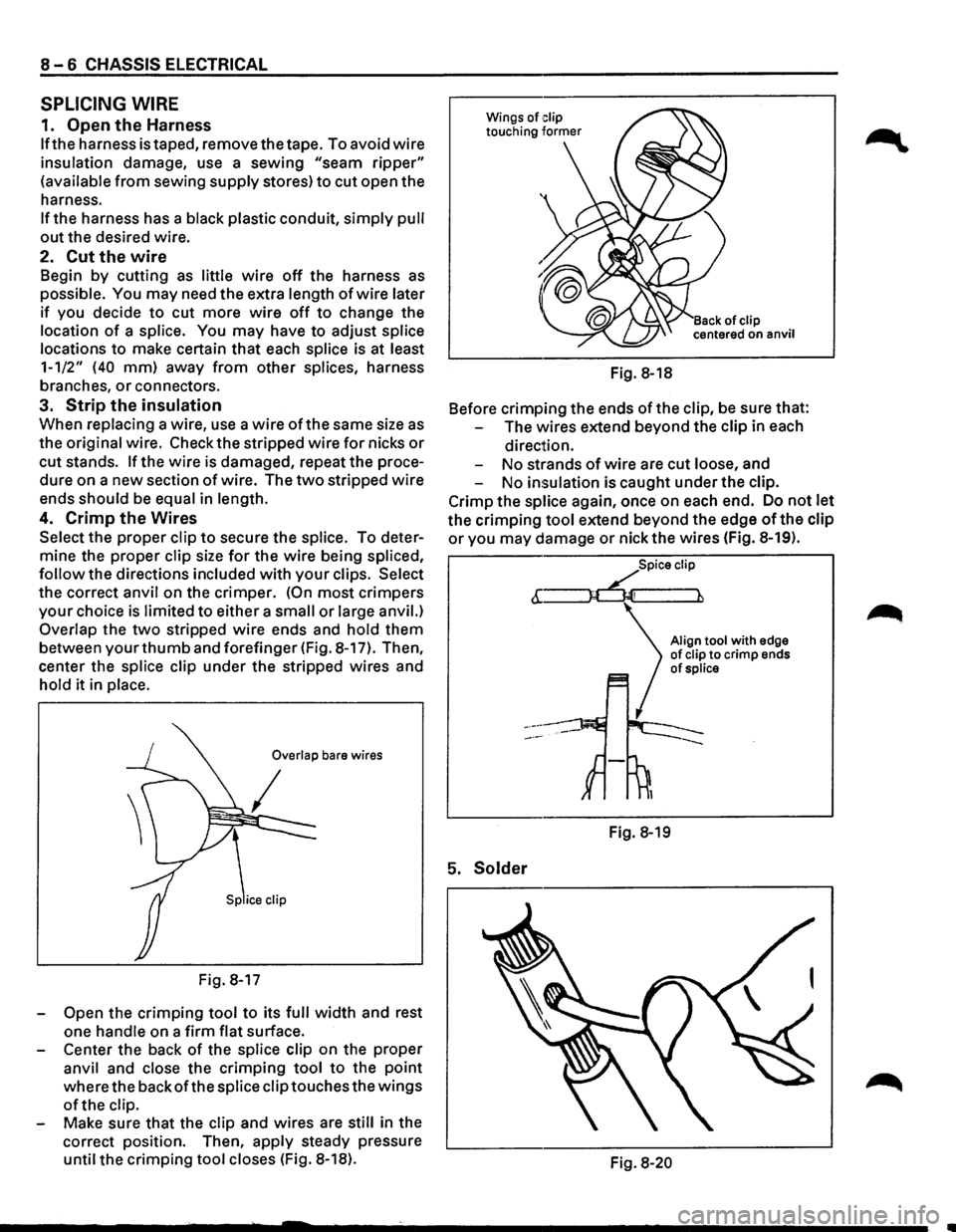
4. Crimp the Wires
Select the proper clip to secure the splice. To deter
mine the proper clip size for the wire being spliced,
follow the directions included with your clips. Select
the correct anvil on the crimper.
{On most crimpers
your choice is limited to either a small or large anvil.)
Overlap the two stripped wire ends and hold them
between your thumb and forefinger {Fig. 8-17). Then,
center the splice clip under
the stripped wires and
hold
it in place.
Overlap bare wires
Fig. 8-17
-
Open the crimping tool to its full width and rest
one handle on a
firm flat surface.
- Center
the back of the splice clip on the proper
anvil and close the
crimping tool to the point
where the backofthe splice clip touches the wings
of the clip.
Make sure
that the clip and wires are still in the
correct position. Then,
apply steady pressure
until
the crimping tool closes {Fig. 8-18). Fig.
8-18
Before
crimping the ends ofthe clip, be sure that:
The wires extend beyond
the clip in each
direction.
No strands of wire are cut loose, and
No insulation is caught under
the clip.
Crimp the splice again, once on each end. Do
not let
the crimping tool extend beyond the edge of the clip
or you may damage or nick the wires (Fig. 8-19).
5. Solder
Spice clip
6:~
Fig. 8-19
Align tool with edge of clip to crimp ends of splice
Fig. 8-20
Page 1197 of 1928
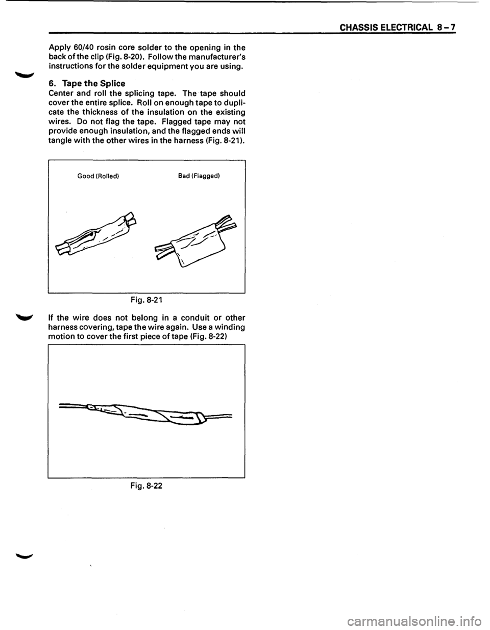
Apply 60/40 rosin core solder to the opening in the
back
of the clip (Fig. 8-20). Follow the manufacturer's
instructions
for the solder equipment you are using.
6. Tape the Splice
Center and roll the splicing tape. The tape should
cover the entire splice.
Roll on enough tape to dupli
cate the thickness of the insulation on the existing
wires. Do
not flag the tape. Flagged tape may not
provide enough insulation, and the flagged ends will
tangle with the other wires in the harness (Fig. 8-21).
Good (Rolled) Bad (Flagged)
Fig. 8-21
"-"' If the wire does not belong in a conduit or other
harness covering, tape the
wire again. Use a winding
motion to cover the first piece of tape (Fig. 8-22)
Fig. 8-22
CHASSIS ELECTRICAL 8-7
Page 1198 of 1928
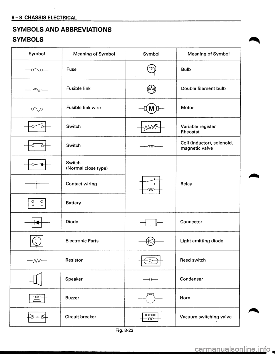
8-8 CHASSIS ELECTRICAL
SYMBOLS AND ABBREVIATIONS
SYMBOLS
Symbol Meaning of Symbol
~ Fuse
~ Fusible link
----if\p-Fusible link wire
~ Switch
~ Switch
-a-
Switch
(Normal close type)
j Contact wiring I
[I] -I
Battery
~
Diode
~
Electronic Parts
--Nt-Resistor
=Q] Speaker
1~1 Buzzer I
-EJ-Circuit breaker
I Symb•:>l Meaning of Symbol
~
Bulb
~ Double filament bulb
-r@[}-Motor
~j-Variable register
Rheostat
Coil (inductor), solenoid,
~-magnetic valve I
§
Relay
-or-Connector
----@-Light emitting diode
~8-
Reed switch
---11----Condenser
I -o-Horn
~t Vacuum switching valve I
Fig. 8-23
•
Page 1199 of 1928
CHASSIS ELECTRICAL 8-9
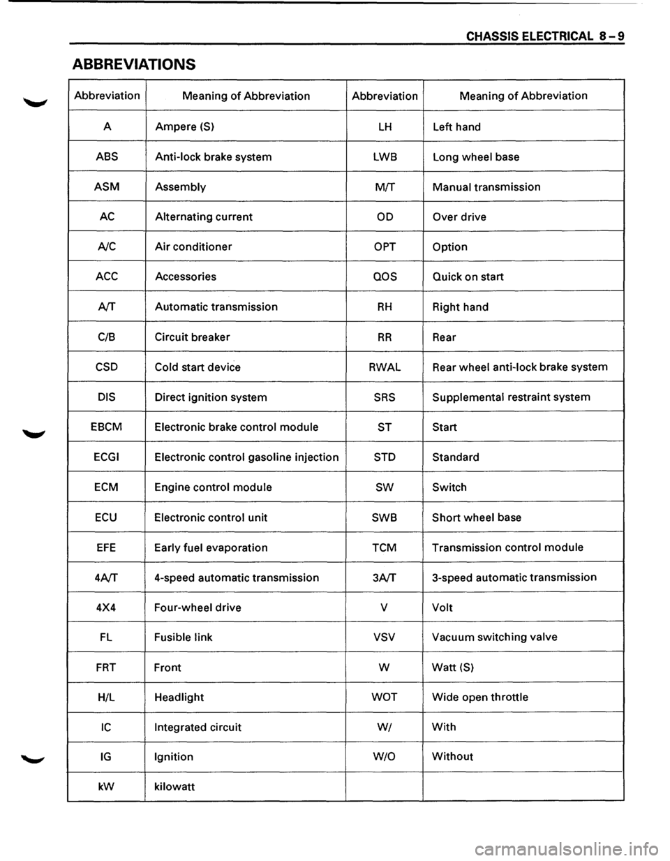
ABBREVIATIONS
Abbreviation
Meaning of Abbreviation Abbreviation Meaning of Abbreviation
A Ampere
(S) LH Left
hand
ABS Anti-lock brake system LWB Long wheel base
ASM Assembly M!f Manual transmission
AC Alternating current OD Over drive
A/C
Air conditioner OPT Option
ACC Accessories QOS Quick on start
A/T Automatic
transmission
RH Right hand
C/8 Circuit
breaker
RR Rear
CSD Cold start device RWAL Rear
wheel anti-lock brake system
DIS Direct ignition system SRS Supplemental restraint system
EBCM Electronic brake control module
ST Start
ECGI Electronic control gasoline injection STD Standard
ECM Engine control module sw Switch
ECU Electronic control unit SWB Short wheel
base
EFE Early fuel evaporation TCM Transmission
control module
4A/T 4-speed
automatic transmission
3A/T 3-speed
automatic transmission
4X4 Four-wheel drive
v Volt
FL Fusible link vsv Vacuum switching valve
FRT Front w Watt {S)
H/L Headlight WOT Wide open throttle
IC Integrated circuit WI With
IG Ignition W/0 Without
kW
kilowatt
Page 1200 of 1928
8-10 CHASSIS ELECTRICAL
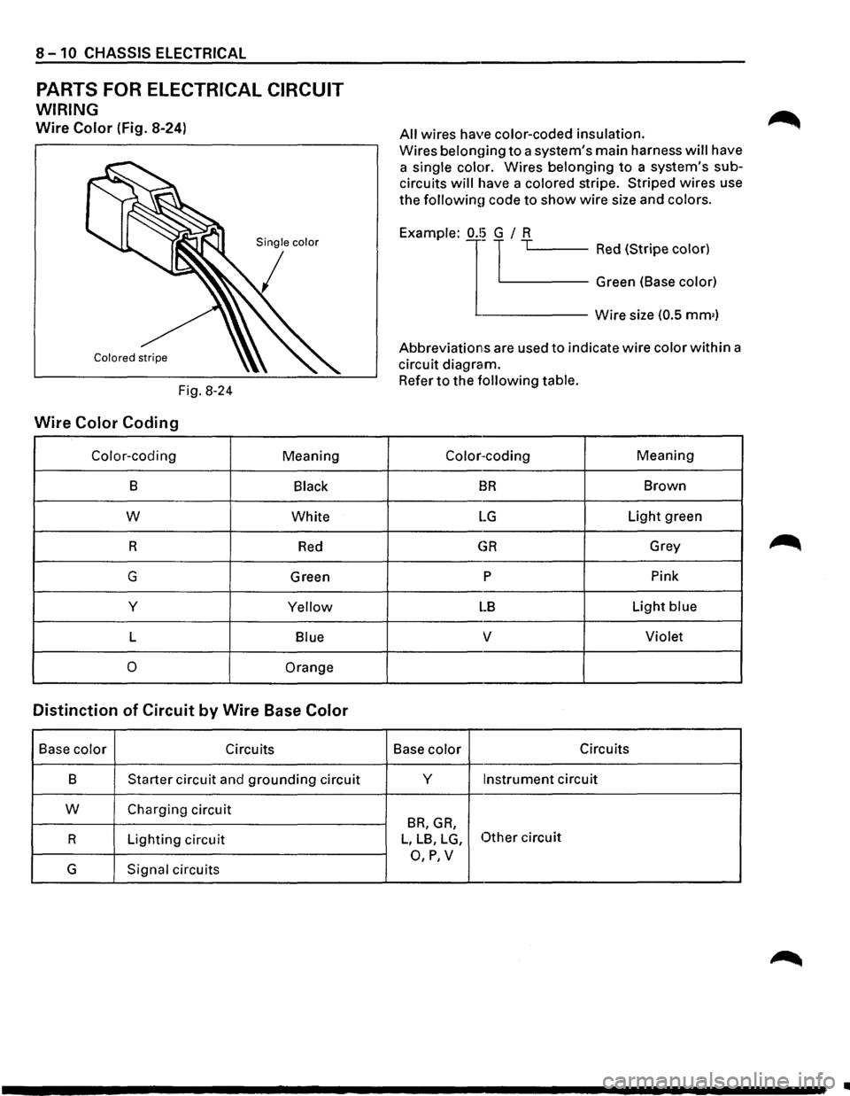
PARTS FOR ELECTRICAL CIRCUIT
WIRING
Wire Color (Fig. 8-24)
Fig. 8-24
Wire Color Coding
Color-coding Meaning
B Black
w White
R
Red
G Green
y
Yellow
L Blue
0 Orange
Distinction of Circuit by Wire Base Color
Base color Circuits
B
Starter circuit and grounding circuit
w Charging circuit
R Lighting circuit
G Signal circuits
All wires have color-coded insulation.
Wires belon{)ing to a system's main harness will have
a
single color. Wires belonging to a system's sub
circuits will have a colored stripe. Striped wires use
the followinu code to show wire size and colors.
j '-----Red (Stripe color) Example:
1
0.!~ TL.-~-~---
Green (Base color)
------Wire size (0.5 mm•)
Abbreviations are used to indicate wire color within a
circuit diagram.
Refer to the following table.
Color-coding Meaning
BR Brown
LG Light green
GR Grey
p Pink
LB Light blue
v Violet
Base color Circuits
y
Instrument circuit
BR, GR,
L, LB, LG, Other circuit
O,P,V