ISUZU TROOPER 1995 Workshop Manual
Manufacturer: ISUZU, Model Year: 1995, Model line: TROOPER, Model: ISUZU TROOPER 1995Pages: 1928
Page 1161 of 1928
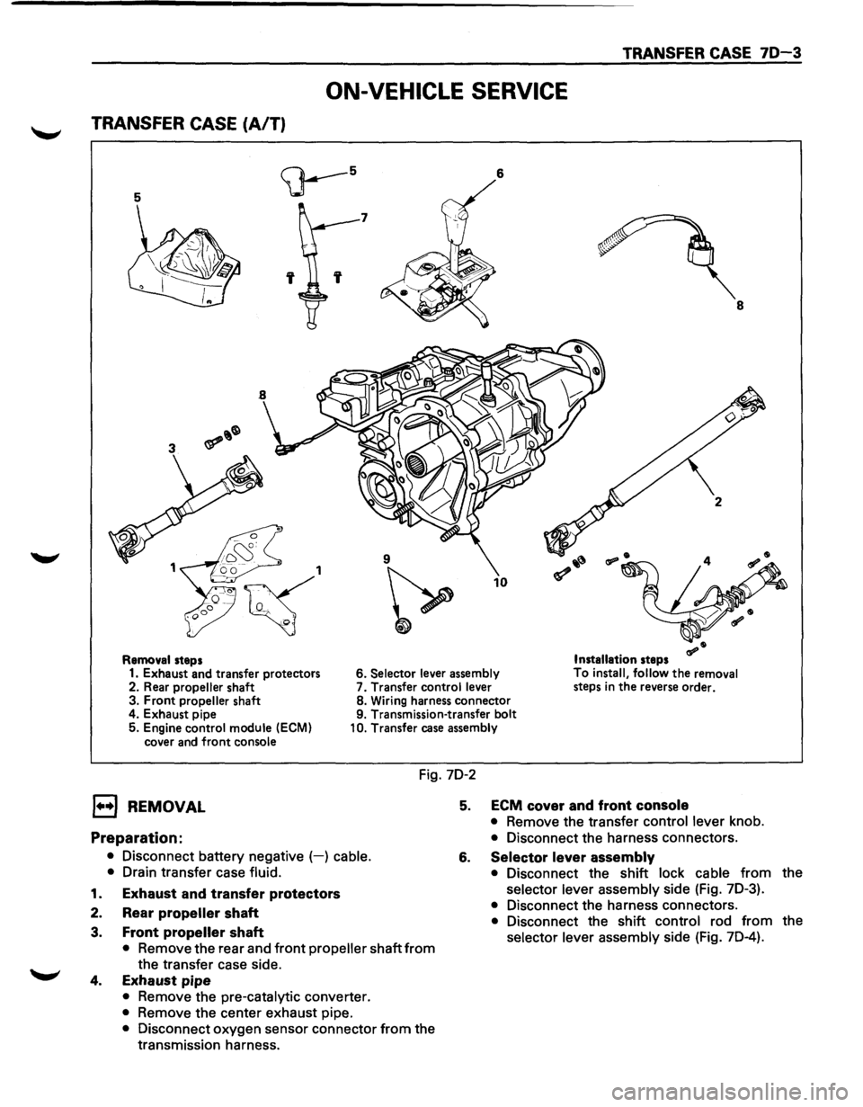
TRANSFER CASE 70-3
ON-VEHICLE SERVICE
TRANSFER CASE (A/T)
5
<;J---5 6
7
' 8
9
~
10
Removal steps Installation steps
1. Exhaust and transfer protectors 6. Selector lever
assembly To
install, follow the removal
steps in the reverse order.
2. Rear propeller shaft 7.
Transfer control lever
3. Front propeller shaft 8.
Wiring harness connector
4. Exhaust pipe 9. Transmission-transfer bolt
5. Engine control module
(ECM)
cover and front console 10.
Transfer case assembly
Fig. 7D-2
l••l REMOVAL
Preparation:
• Disconnect battery negative (-) cable.
•
Drain transfer case fluid.
1. Exhaust and transfer protectors
2. Rear propeller shaft
3. Front propeller shaft
• Remove the rear and front propeller shaft from
the transfer case side.
4. Exhaust pipe
• Remove the pre-catalytic converter.
• Remove the center exhaust pipe.
• Disconnect oxygen sensor connector from the
transmission harness.
5. ECM cover and front console
• Remove the transfer control lever knob.
• Disconnect the harness connectors.
6. Selector lever assembly
• Disconnect the shift lock cable from the
selector lever assembly side (Fig. 7D-3).
• Disconnect the harness connectors.
• Disconnect the shift control rod from the
selector lever assembly side (Fig. 7D-4).
Page 1162 of 1928
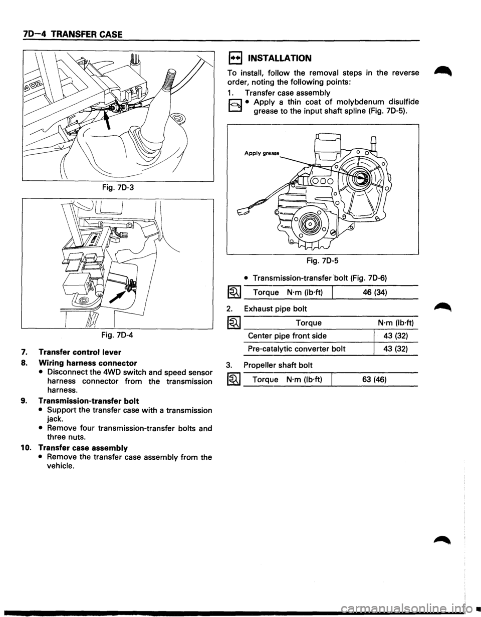
70-4 TRANSFER CASE
Fig. 70-3
Fig. 70-4
7. Transfer control lever
8. Wiring harness connector
• Disconnect the 4WD switch and speed sensor
harness connector from the transmission
harness.
9. Transmission-transfer bolt
• Support the transfer case with a transmission
jack.
• Remove four transmission-transfer bolts and
three nuts.
10. Transfer case assembly
• Remove the transfer case assembly from the
vehicle.
1••1 INSTALLATION
To install, follow the removal steps in the reverse ~
order, noting the following points:
1. Transfer case assembly
r;:;J • Apply a thin coat of molybdenum disulfide
D grease to the input shaft spline (Fig. 70-5).
Fig. 70-5
• Transmission-transfer bolt (Fig. 70-6)
1~1 Torque N·m (lb·ft)
2. Exhaust pipe bolt
1~1 Torque
Center pipe front side
Pre-catalytic converter bolt
3. Propeller shaft bolt
1~1 Torque N·m (lb·ft)
46 (34)
N·m (lb·ft)
43 (32)
43 (32)
63 (46)
•
Page 1163 of 1928
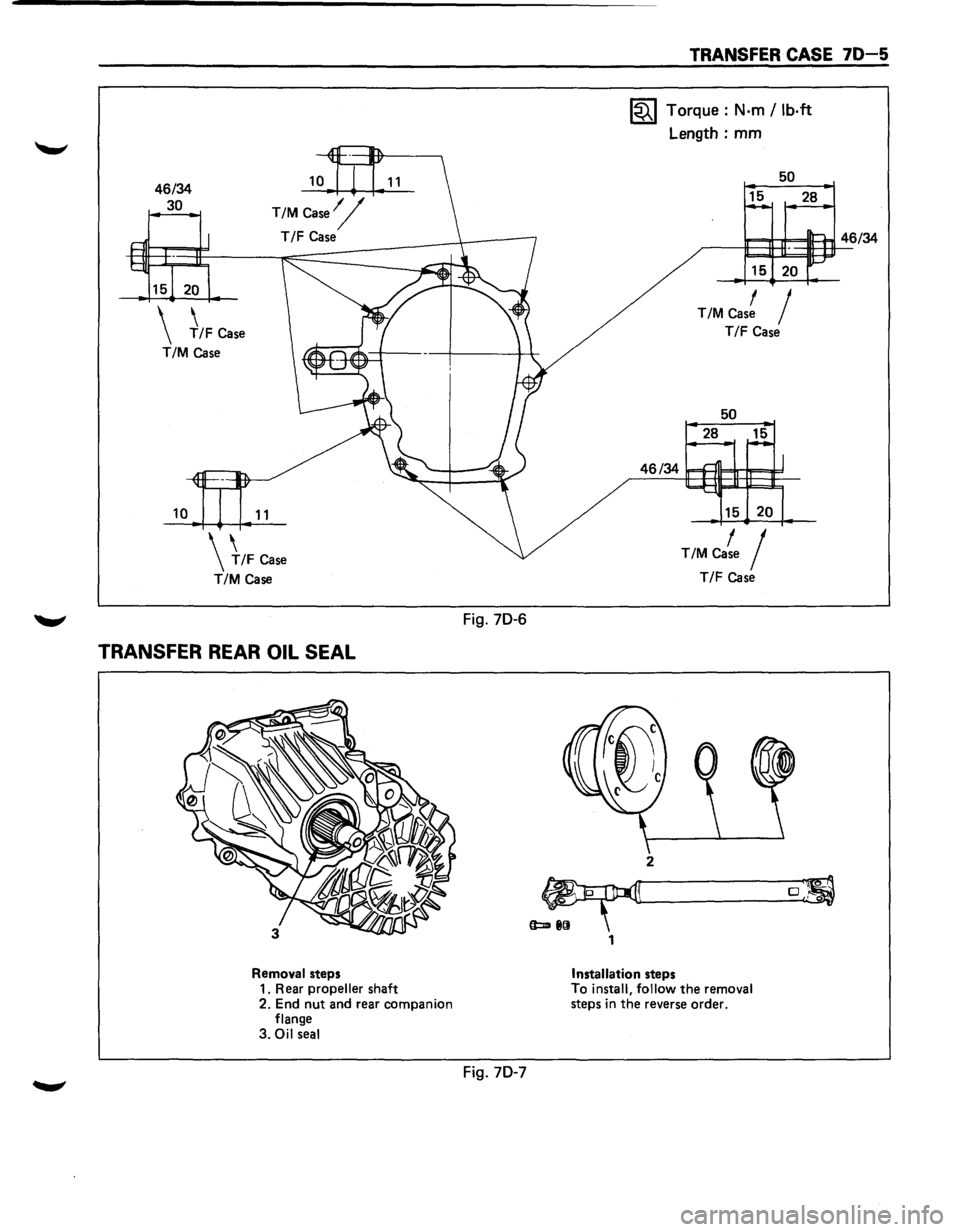
46/34
30
T/F Case
T/M case
+/F Case
T/M Case
TRANSFER REAR OIL SEAL
Removal steps
1. Rear propeller shaft
2. End nut and rear companion
flange
3.
Oil seal
Fig. 70-6
Fig. 70-7
1
TRANSFER CASE 70-5
1~1 Torque: N·m /lb·ft
Length: mm
50
15 28
15 20
T/M Cas! I
T/F Case
50
28 15
T/M Ca~e I
T/F case
2
0 ,""o
Installation steps
To install, follow the removal
steps in the reverse order.
Page 1164 of 1928
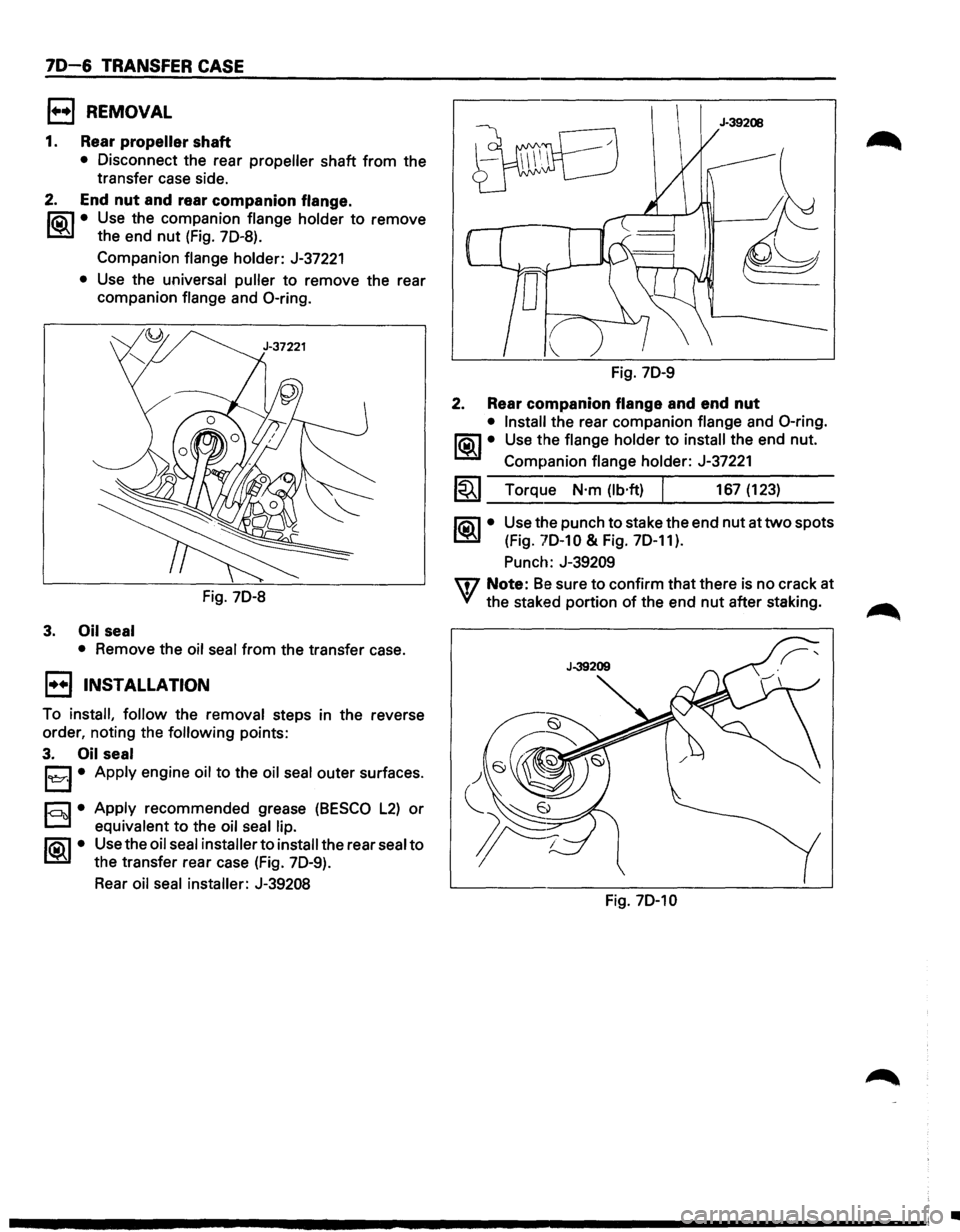
70-6 TRANSFER CASE
EJ REMOVAL
1. Rear propeller shaft
• Disconnect the rear propeller shaft from the
transfer case side.
2. End nut and rear companion flange.
li5\l • Use the companion flange holder to remove
~ the end nut (Fig. 70-8).
Companion flange holder: J-37221
• Use the universal puller to remove the rear
companion flange and 0-ring.
Fig. 70-8
3. Oil seal
•
Remove the oil seal from the transfer case.
1••1 INSTALLATION
To install, follow the removal steps in the reverse
order, noting the
following points:
3. Oil seal
l
D equivalent to the oil seal lip.
li5\l • Use the oil seal installer to install the rear seal to
~ the transfer rear case (Fig. 70-9).
Rear oil seal installer: J-39208
Fig. 70-9
2. Rear companion flange and end nut
• Install the rear companion flange and 0-ring.
l<9l..l• Use the flange holder to install the end nut.
Companion flange holder:
J-37221
1~1 Torque N·m (lb·ft) I 167 (123)
~·
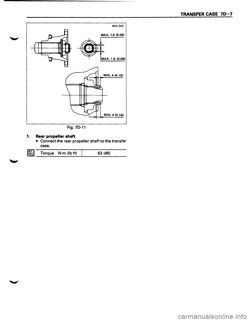
Use the punch to stake the end nut at two spots
(Fig.
70-10 & Fig. 70-11).
Punch: J-39209
m Note: Be sure to confirm that there is no crack at
VI the staked portion of the end nut after staking.
Fig. 70-10
•
Page 1165 of 1928
TRANSFER CASE 70-7
mm(in)
MAX. 1.5 (0.06)
MAX. 1.5 (0.06)
MIN. 4 (0.16)
MIN. 4 (0.16)
Fig. 70-11
1. Rear propeller shaft
• Connect the rear propeller shaft to the transfer
case.
l~l Torque N·m (lb·ft) 63 (46)
Page 1166 of 1928
70-8 TRANSFER CASE
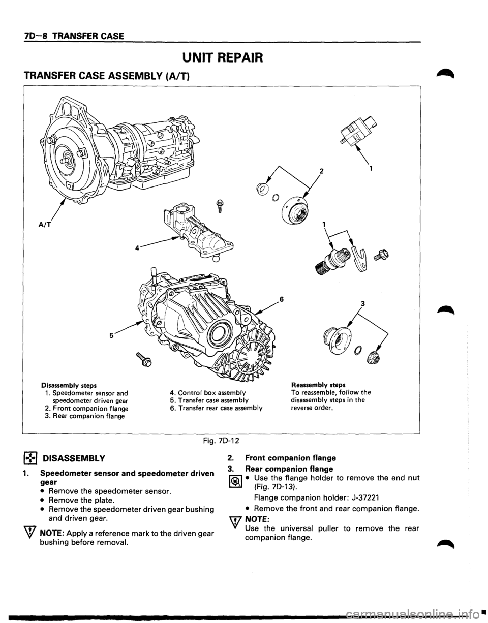
UNIT REPAIR
TRANSFER CASE ASSEMBLY (A/T)
1
A/T
3
5
Disassembly steps Reassembly
steps
1. Speedometer sensor and
speedometer driven gear 4. Control box assembly To reassemble,
follow the disassembly steps in the
reverse order.
5.
Transfer case assembly
2. Front companion flange 6. Transfer rear case assembly
3. Rear companion flange
Fig. 70-12
j .. ! .. j DISASSEMBLY
1. Speedometer sensor and speedometer driven
gear
• Remove the speedometer sensor.
• Remove the plate.
•
Remove the speedometer driven gear bushing
and driven gear.
W NOTE: Apply a reference mark to the driven gear
bushing before
removal.
2. Front companion flange
3. Rear companion flange
li5\l • Use the flange holder to remove the end nut
~ (Fig. 7D-13).
Flange companion holder: J-37221
• Remove the front and rear companion flange.
\flNOTE:
'if Use the universal puller to remove the rear
companion
flange.
•
Page 1167 of 1928
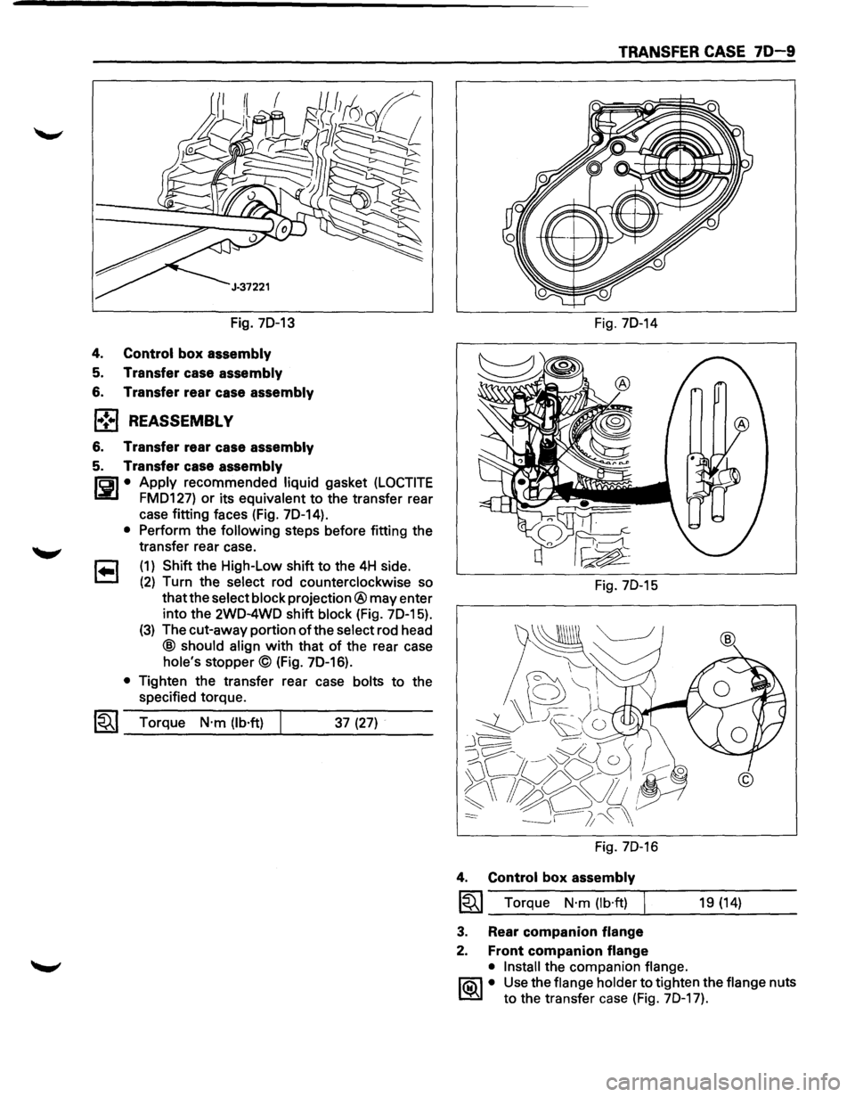
Fig. 70-13
4.
Control box assembly
5. Transfer case assembly
6. Transfer rear case assembly
l•!•l REASSEMBLY
6. Transfer rear case assembly
5. Transfer case assembly
1'61 • Apply recommended liquid gasket (LOCTITE
Li!:l FM0127) or its equivalent to the transfer rear
case fitting faces (Fig. 70-14).
• Perform the following steps before fitting the
transfer rear case.
1 .. 1 (1) Shift the High-Low shift to the 4H side.
(2) Turn the select rod counterclockwise so
that the select block projection® may enter
into the 2W0-4WO shift
block (Fig. 70-15).
(3) The cut-away portion of the select rod head
@ should align with that of the rear case
hole's stopper© (Fig. 70-16).
• Tighten the transfer rear case bolts to the
specified torque.
1~1 Torque N·m (lb·ft) 37 (27)
TRANSFER CASE 70-9
Fig. 70-14
Fig. 70-15
Fig. 70-16
4. Control box assembly
~~~ Torque N·m (lb·ft) 19 (14)
3. Rear
companion flange
2. Front companion flange
• Install
the companion flange.
l"iC\l • Use the flange holder to tighten the flange nuts
~ to the transfer case (Fig. 70-17).
Page 1168 of 1928
70-10 TRANSFER CASE
~·
Companion flange holder: J-37221
Tighten
new transfer flange nuts to the
specified torque.
Torque
N·m (lb·ft)
Rear companion flange 167(123)
Front companion
flange 137 (101)
Fig. 70-17
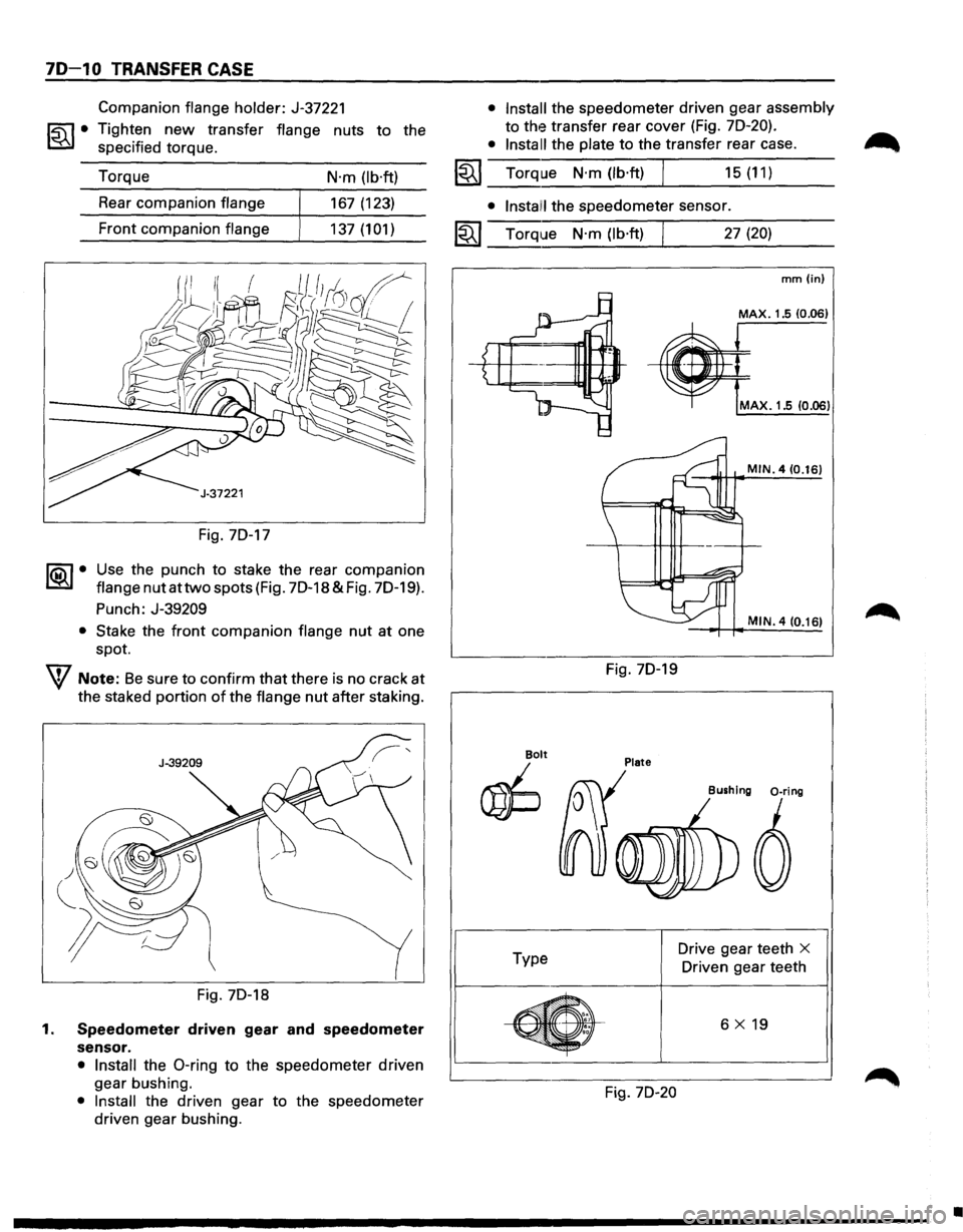
1®..1• Use the punch to stake the rear companion
flange nut at two spots (Fig. 7D-18 & Fig. 70-19).
Punch: J-39209
• Stake the front companion flange nut at one
spot.
W Note: Be sure to confirm that there is no crack at
the staked portion of the flange nut after staking.
Fig. 70-18
1. Speedometer driven gear and speedometer
sensor.
• Install the 0-ring to the speedometer driven
gear bushing.
• Install the driven gear to the speedometer
driven gear bushing.
• Install the speedometer driven gear assembly
to the transfer rear cover (Fig. 7D-20).
• Install the plate to the transfer rear case.
~~~ Torque N·m(lb·ft) J 15(11)
• Instal!! the speedometer sensor.
I~I __ T_o_rq~u_e __ N_·_m_(_lb_·ft_l~ ______ 2_7_(2_0_) ____ _
Bolt
~
Type
•
' . '
Fig. 70-19
Plate
Fig. 7D-20
mm (in)
MAX. 1.5 10.06)
MAX. 1.5 (0.06)
MIN. 4 (0.16)
MIN. 4 (0.161
Drive gear teeth X
Driven gear teeth
6
X 19
•
Page 1169 of 1928
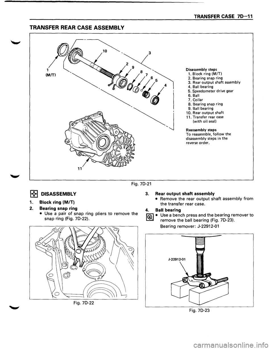
TRANSFER REAR CASE ASSEMBL V
TRANSFER CASE 70-11
Disassembly steps 1. Block ring (M/T)
2. Bearing snap ring
3. Rear
output shaft assembly
4. Ball bearing
5. Speedometer drive gear
6. Ball
7.
Collar 8. Bearing snap ring
9. Ball bearing
10. Rear output shaft 11. Transfer rear case
(with oil seal)
Reassembly steps
To reassemble, follow the disassembly steps in the reverse order.
Fig. 70-21
l•!•l DISASSEMBLY
1. Block ring (MIT)
2. Bearing snap ring
• Use a pair of snap ring pliers to remove the
snap ring (Fig. 70-22).
Fig. 70-22
3. Rear output shaft assembly
• Remove the rear output shaft assembly from
the transfer rear case.
4. Ball bearing
I'Qi) • Use a bench press and the bearing remover to
~ remove the ball bearing (Fig. 70-23).
Bearing remover:
J-22912-01
J-22912-01
Fig. 70-23
Page 1170 of 1928

70-12 TRANSFER CASE
5. Speedometer drive gear
6. Ball
7. Collar
8. Bearing snap ring
• Use a pair of snap ring pliers to remove the
snap ring.
9. Ball bearing
10. Rear output shaft
l'iC\1 • Use a bench press and the bearing remover to
~ remove the ball bearing (Fig. 70-24).
Bearing remover: J-22912-01
11. Transfer rear case (with oil seal)
Fig. 70-24
Wtl INSPECTION AND REPAIR
Refer to "TRANSFER CASE ASSEMBLY" in this Section
for inspection and repair.
l•!•l REASSEMBLY
11. Transfer rear case (with oil seal)
Oil seal
replacement
• Remove the oil seal from the transfer rear case.
D • Apply engine oil to the oil seal outer surfaces. 12::::]
§1•
~·
Fill in recommended grease (BESCO L2) or
equivalent in the oil seal lip.
Use the oil seal installer to install the rear oil
seal
to the transfer rear case (Fig. 70-25).
Oil
seal installer: J-39208
Fig. 70-25
10.
Rear output shaft
9. Ball bearing
l'iC\1 • Use the ball bearing installer and the adapter to
~ instalil the ball bearing (Fig. 70-26).
Ball
bearing installer: J-37223
Adap1ter: J-37486
Fig. 70-26
8. Bearing snap ring
7. Collar
6. Ball
J.37486
5. Speedometer drive gear (Fig. 70-27)
4. Ball bearing
liC\1 • Use the ball bearing installer to install the ball
~ bearing (Fig. 70-28).
Ball
be1aring installer: J-37223
•