automatic transmission ISUZU TROOPER 1995 Workshop Manual
[x] Cancel search | Manufacturer: ISUZU, Model Year: 1995, Model line: TROOPER, Model: ISUZU TROOPER 1995Pages: 1928
Page 996 of 1928
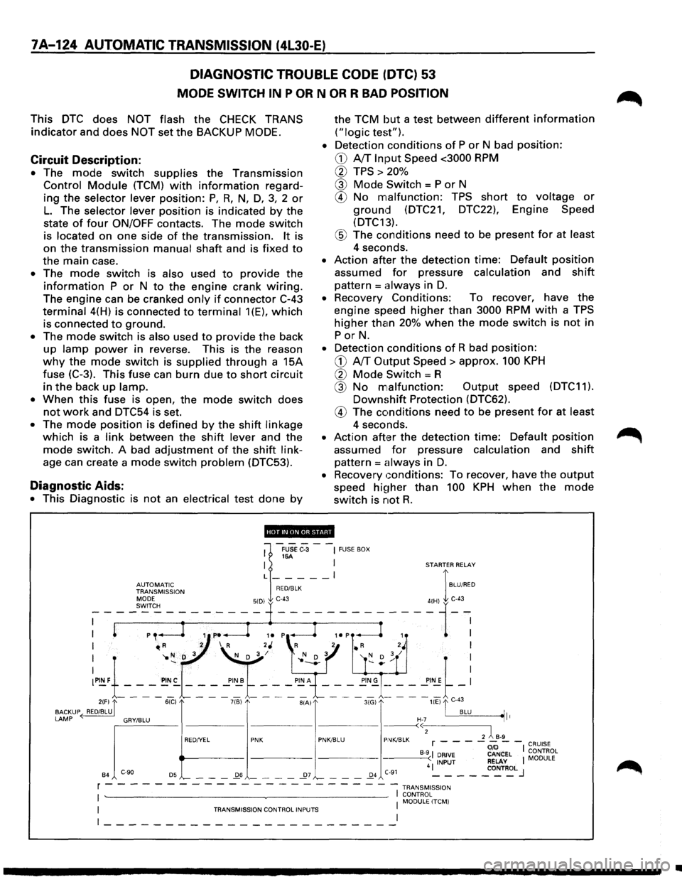
7A-124 AUTOMATIC TRANSMISSION (4L30-E)
DIAGNOSTIC TROUBLE CODE (DTC) 53
MODE SWITCH IN P OR N OR R BAD POSITION
This DTC does NOT flash the CHECK TRANS
indicator and does NOT set the BACKUP MODE.
Circuit Description:
• The mode switch supplies the Transmission
Control Module (TCM) with information regard
ing
the selector lever position: P, R, N, D, 3, 2 or
L. The selector lever position is indicated by the
state
of four ON/OFF contacts. The mode switch
is located on one side of the transmission. It is
on
the transmission manual shaft and is fixed to
the main case.
• The mode switch is also used to provide the
information P or N to the engine crank wiring.
The engine can be cranked only if connector C-43
terminal 4(H) is connected to terminal 1(E), which
is connected to ground.
• The mode switch is also used to provide the back
up lamp power in reverse. This is the reason
why the mode switch is supplied through a 15A
fuse
(C-3). This fuse can burn due to short circuit
in the back up lamp.
•
When this fuse is open, the mode switch does
not work and DTC54 is set.
• The mode position is defined by the shift linkage
which is a link between the shift lever and the
mode switch. A bad adjustment of the shift link
age can create a mode switch problem (DTC53).
Diagnostic Aids:
• This Diagnostic is not an electrical test done by
the TCM but a test between different information
("logic test").
•
Detection conditions of P or N bad position:
CD A/T Input Speed <3000 RPM
0 TPS > 20%
@ Mode Switch = P or N
® No malfunction: TPS short to voltage or
ground (DTC21, DTC22), Engine Speed
(DTC13).
® The conditions need to be present for at least
4 seconds.
• Action after the detection time: Default position
assumed for pressure calculation and shift
pattern =always in D.
• Recovery Conditions: To recover, have the
engine speed higher than 3000 RPM with a TPS
higher than 20% when the mode switch is not in
PorN.
• Detection conditions of R bad position:
CD A/T Output Speed> approx. 100 KPH
0 Mode Switch= R
@ No malfunction: Output speed (DTC11).
Downshift Protection (DTC62).
® The conditions need to be present for at least
4 seconds.
• Action aft,:H the detection time: Default position
assumed for pressure calculation and shift
pattern = always in D.
• Recovery conditions: To recover, have the output
speed hi~1her than 100 KPH when the mode
switch is not R.
'''·"'·'lllfHJi'.!d'
1
-FUSe C-3 --~ FUSE BOX 16A I I STARTER RELAY
L _____ l I
~~J~Jr'~~~ION RED/BLK BLU/RED
I "'R 2 I R 2J 'R 2 • R 2J I
I '1o N D 3 ~/ l' N D 3 '( D ; / I
:~1-_-_-_~:-~ ~ ~'~t ~-: ~"~\_-_-~-_!!;~= = = ==~-: 2(F) "[ 6(C) 7(B) BIA) 3(G) liE) "'I C-43
BACKUP ( RED/BLU. . BLU ~It
LAMP ~'"""" "'""" "' e>
B4 '-- - -_Q6 - - - -_27 '-- - -_Q4 C-91 4 ~ - - -_co~T~L J
r - - - - - - - - - - - - - - - - - --- -- -1 TRANsM1ss1oN
I ~~~0RL~LITCM) I TRANSMISSION CONTROL INPUTS I
~-----------------------~
•
Page 997 of 1928
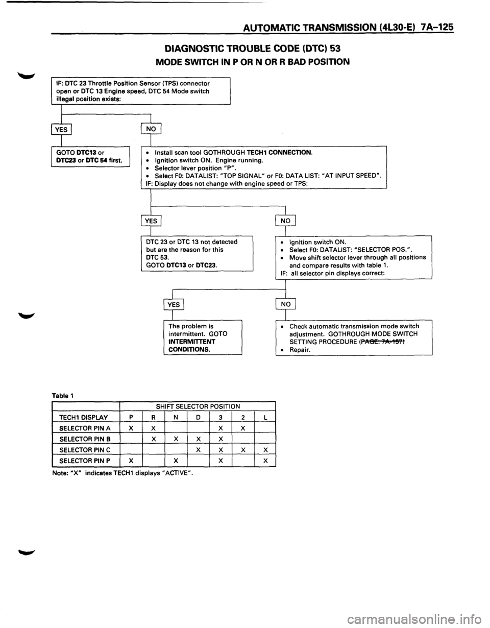
AUTOMATIC TRANSMISSION (4l30-E) 7 A-125
DIAGNOSTIC TROUBLE CODE (DTC) 53
MODE SWITCH IN P OR N OR R BAD POSITION
IF: DTC 23 Throttle Position Sensor (TPS) connector
open or DTC 13 Engine speed, DTC 54 Mode switch
illegal position exists:
Table 1
TECH1 DISPLAY p
SELECTOR PIN A X
SELECTOR PIN B
SELECTOR PIN C
SELECTOR PIN P X
• Install scan tool GOTHROUGH TECH1 CONNECTION.
• Ignition switch ON. Engine running.
• Selector lever position "P". • Select FO: DATALIST: "TOP SIGNAL" or FO: DATA LIST: "AT INPUT SPEED".
IF: Display does not change with engine speed or TPS:
DTC 23 or DTC 13 not detected
but are the reason for this DTC 53.
GOTO DTC13 or DTC23.
R
X
X
The problem is
intermittent. GOTO
INTERMITTENT
CONDITIONS.
SHIFT
SELECTOR POSITION
N D
3
X
X X X
X
X
X X
2 L
X
X X
X
• Ignition switch ON.
• Select FO: DATALIST: "SELECTOR POS.".
• Move shift selector lever through all positions
and compare
results with table 1. IF: all selector pin displays correct:
• Check automatic transmission mode switch
adjustment. GOTHROUGH MODE SWITCH
SETTING PROCEDURE (~. ;"A•1~'Yl
• Repair.
Note:
"X" indicatesTECH1 displays "ACTIVE".
Page 998 of 1928
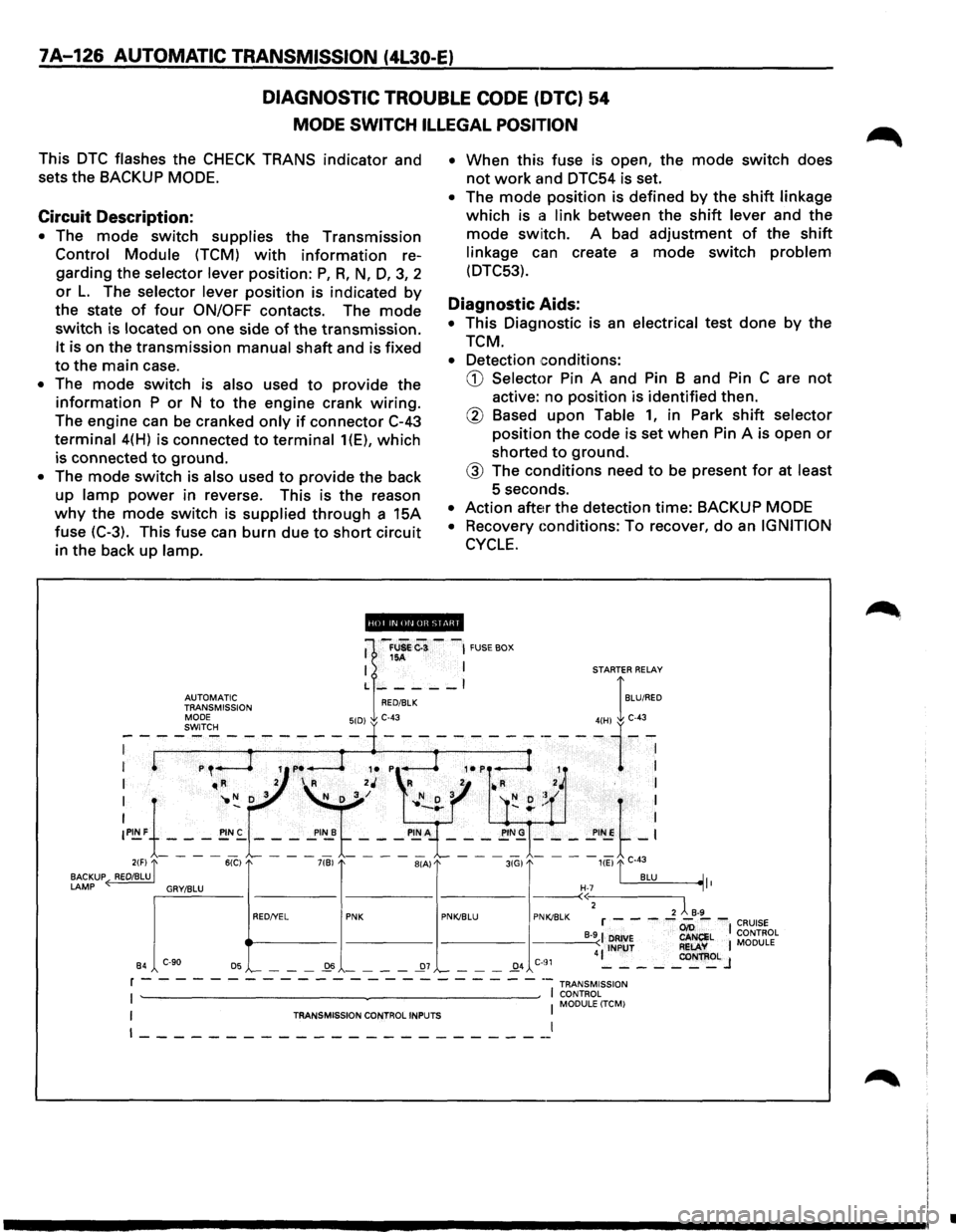
7A-126 AUTOMATIC TRANSMISSION (4L30-E)
DIAGNOSTIC TROUBLE CODE (DTC) 54
MODE SWITCH ILLEGAL POSITION
This DTC flashes the CHECK TRANS indicator and
sets the BACKUP
MODE.
Circuit Description:
• The mode switch supplies the Transmission
Control Module (TCM) with information re
garding the
selector lever position: P, R, N, D, 3, 2
or L. The selector lever position is indicated by
the state of four ON/OFF contacts. The mode
switch is located on one side of the transmission.
It is on the transmission manual shaft and is fixed
to the main case.
• The mode switch is also used to provide the
information P or N to the engine crank wiring.
The engine can be cranked only if connector C-43
terminal 4(H) is connected to terminal 1(E), which
is connected to ground.
• The mode switch is also used to provide the back
up
lamp power in reverse. This is the reason
why the mode switch is supplied through a 15A
fuse (C-3). This fuse can burn due
to short circuit
in the back
up lamp. •
When
this fuse is open, the mode switch does
not work and DTC54 is set.
• The mode position is defined by the shift linkage
which is a link between the shift lever and the
mode switch. A bad adjustment of the shift
linkage can create a mode switch problem
(DTC53).
Diagnostic Aids:
• This Diagnostic is an electrical test done by the
TCM.
• Detection conditions:
CD Selector Pin A and Pin B and Pin C are not
active: no position is identified then.
@ Based upon Table 1, in Park shift selector
position the code is set when Pin A is open or
shorted to ground.
@ The conditions need to be present for at least
5 seconds.
• Action after the detection time: BACKUP MODE
•
Recovery Gonditions: To recover, do an IGNITION
CYCLE.
ii!Qpi.lifiiUI@ii!ll
•
Page 999 of 1928
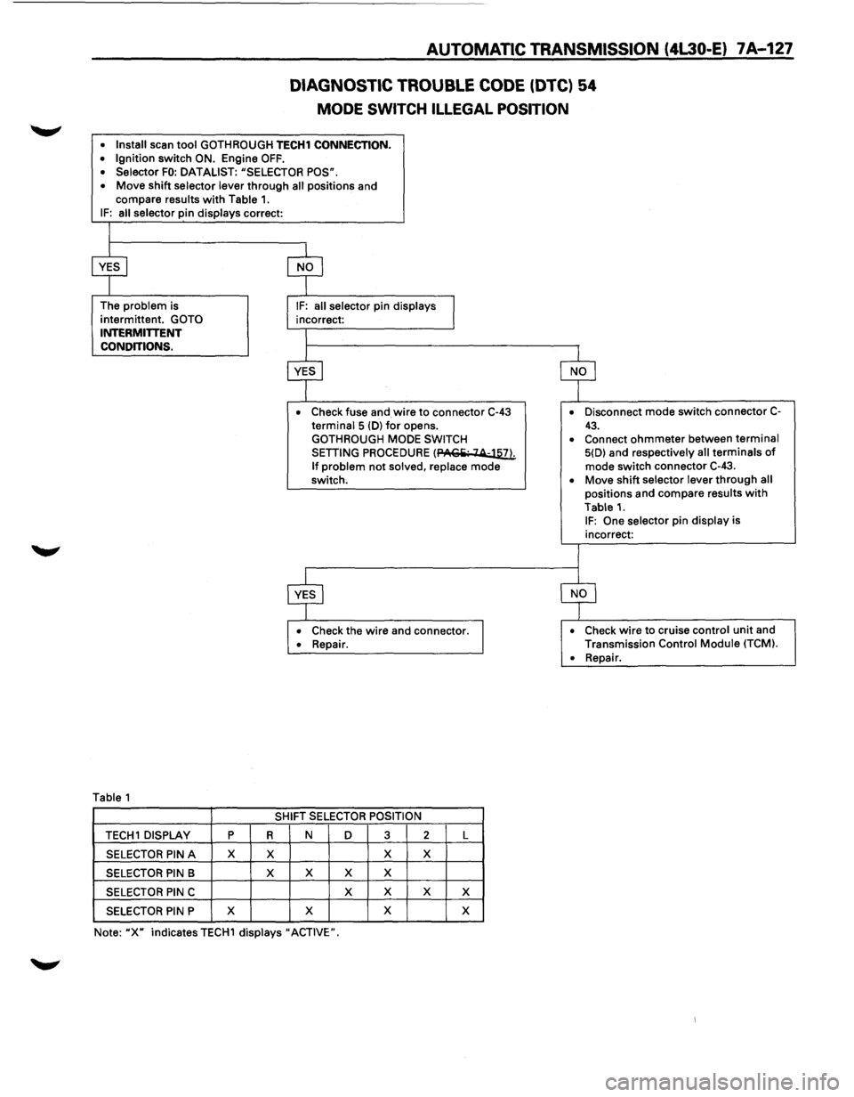
AUTOMATIC TRANSMISSION (4L30-E) 7A-127
DIAGNOSTIC TROUBLE CODE (DTC) 54
MODE SWITCH ILLEGAL POSITION
• Install scan tool GOTH ROUGH TECH1 CONNECTION. • Ignition switch ON. Engine OFF. • Selector FO: DATALIST: "SELECTOR POS".
• Move shift selector lever through all positions and
compare results with Table 1. IF: all selector pin displays correct:
The
problem is
intermittent.
GOTO INTERMITTENT
CONDITIONS.
Table 1
• Check fuse and wire to connector C-43 terminal 5 (D) for opens.
GOTHROUGH MODE SWITCH
SETTING PROCEDURE (PACiii· 14-llli
If problem not solved, replace mode
switch.
• Check the wire and connector. • Repair.
SHIFT SELECTOR POSITION
TECH 1 DISPLAY p R N D 3 2 L
SELECTOR PIN A X X X X
SELECTOR PIN B X
X X X
SELECTOR PIN C X
X X X
SELECTOR PIN P X
X X
X
Note: "X" indicates TECH1 displays" ACTIVE". •
Disconnect
mode switch connector C-
43. • Connect ohmmeter between terminal 5(D) and respectively all terminals of mode switch connector C-43.
• Move shift selector lever through all positions and compare results with
Table 1. IF: One selector pin display is
incorrect:
• Check wire to cruise control unit and
Transmission Control Module (TCM).
•
Repair.
Page 1000 of 1928
7A-128 AUTOMATIC TRANSMISSION (4L30-E)
DIAGNOSTIC TROUBLE CODE (DTC) 55
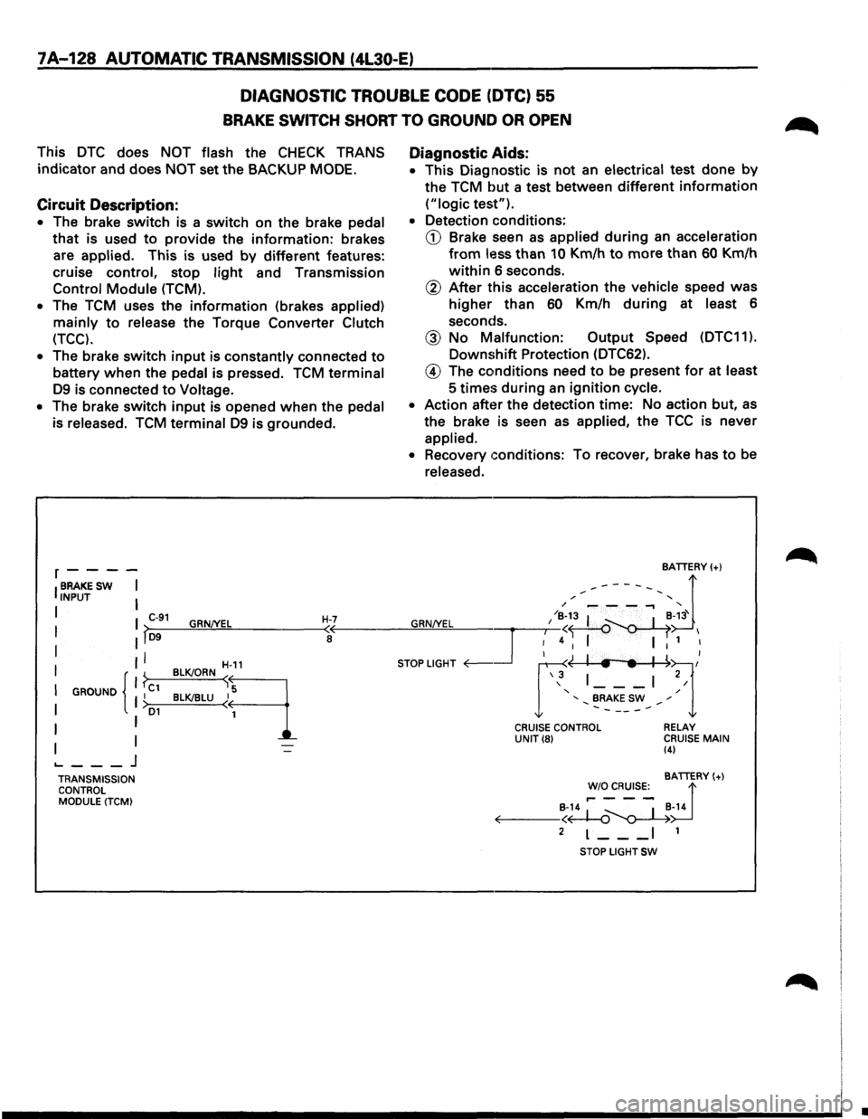
BRAKE SWITCH SHORT TO GROUND OR OPEN
This DTC does NOT flash the CHECK TRANS
indicator and does NOT set the BACKUP MODE.
Circuit Description:
• The brake switch is a switch on the brake pedal
that is used to provide the information: brakes
are
applied. This is used by different features:
cruise control, stop
light and Transmission
Control Module (TCM).
•
The TCM uses the information (brakes applied)
mainly to release the Torque Converter Clutch
(TCC).
•
The brake switch input is constantly connected to
battery when the pedal is pressed. TCM terminal
D9 is connected to Voltage.
• The brake switch input is opened when the pedal
is released.
TCM terminal D9 is grounded.
r----
IBRAKESW I INPUT I
I I C-91 GRN/YEL H-7 I >-D9--~~~------~<
I II a
II
I GROUND I C1 I { }
I I >D1
I I
I I ._ ___ j
TRANSMISSION
CONTROL
MODULE (TCM) BLK!ORN
~-11
B~LU~q
Diagnostic
Aids:
• This Diagnostic is not an electrical test done by
the TCM but a test between different information
("logic test").
• Detection conditions:
CD Brake seen as applied during an acceleration
from less than 10 Km/h to more than 60 Km/h
within 6 seconds.
@ After this acceleration the vehicle speed was
higher than 60 Km/h during at least 6
seconds.
@ No Malfunction: Output Speed (DTC11 ).
Downshift Protection (DTC62).
@ The conditions need to be present for at least
5
times during an ignition cycle.
• Action after the detection time: No action but, as
the brake is seen as applied, the TCC is never
applied.
• Recovery conditions: To recover, brake has to be
released.
CRUISE CONTROL UNIT(8) RELAY
CRUISE MAIN (4)
BATTERY(+)
!'~~s:_ d B-14 ~ _ I _B-14 ~--<~~
2 L--_I 1
STOP LIGHT SW
•
Page 1001 of 1928
AUTOMATIC TRANSMISSION (4L30-E) 7A-129
DIAGNOSTIC TROUBLE CODE (DTC) 55
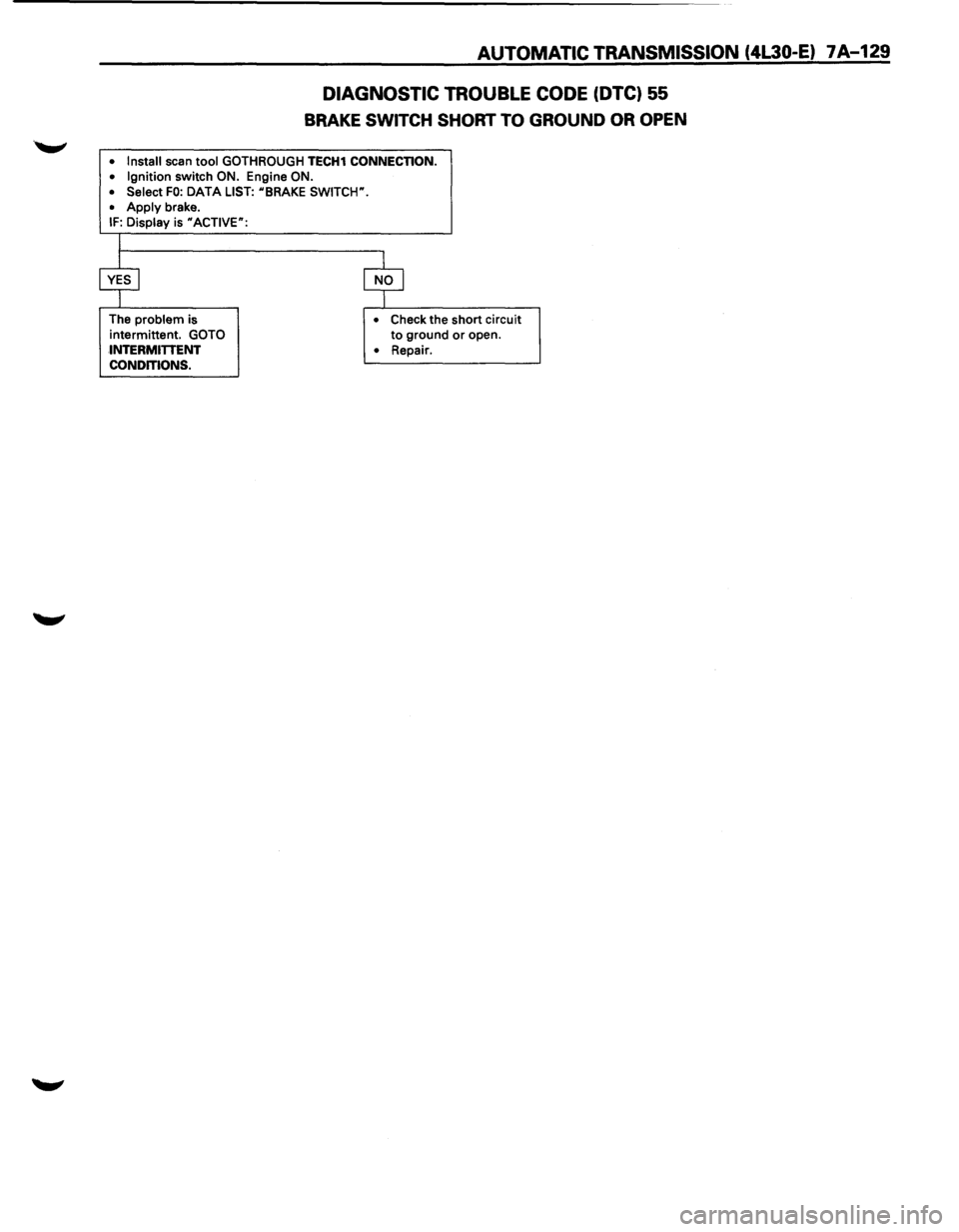
BRAKE SWITCH SHORT TO GROUND OR OPEN
• Install scan tool GOTHROUGH TECH1 CONNECTION.
• Ignition switch ON. Engine ON.
• Select FO: DATA LIST: uBRAKE SWITCW.
•
Apply brake. IF: Display is uACTIVE":
The problem is
intermittent.
GOTO
INTERMITTENT
CONDITIONS. •
Check the short circuit to ground or open.
• Repair.
Page 1002 of 1928
7A-130 AUTOMATIC TRANSMISSION (4l30-E)
DIAGNOSTIC
TROUBLE CODE (DTC)·56
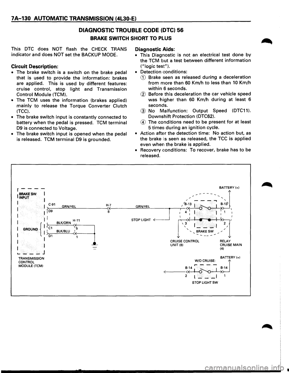
BRAKE SWITCH SHORT TO PLUS
This DTC does NOT flash the CHECK TRANS
indicator and does
NOT set the BACKUP MODE.
Circuit Description:
• The brake switch is a switch on the brake pedal
that is used to provide the information: brakes
are
applied. This is used by different features:
cruise
control, stop light and Transmission
Control Module (TCM).
•
The TCM uses the information (brakes applied)
mainly to release the Torque Converter Clutch
(TCC).
• The brake switch input is constantly connected to
battery when the pedal is pressed. TCM terminal
D9 is connected to Voltage.
•
The brake switch input is opened when the pedal
is released. TCM terminal D9 is grounded.
r----
IBRAKESW I INPUT I
I I C-91 GRN!YEL H-7 I lf~D-9--~~~------~~
I II I
I GROUND { 1 ?c1 II I >o1
I I
I I
.._ ___ J
TRANSMISSION
CONTROL
MODULE (TCM)
H-11
BLK!ORN sq
BLK!BLU ~
1
Diagnostic Aids:
• This Diagnostic is not an electrical test done by
the TCM but a test between different information
("logic test").
•
Detection conditions:
CD Brake seen as released during a deceleration
from more than 60 Km/h to less than 10 Km/h
within 6 seconds.
® Before this deceleration the car vehicle speed
was
higher than 60 Km/h during at least 6
seconds.
@ No Malfunction: Output Speed (DTC11).
Downshift Protection (DTC62).
@ The conditions need to be present for at least
5 times; during an ignition cycle.
•
Action atte~r the detection time: No action but, as
the brake is seen as released, the TCC is applied
even when the brake is applied.
•
Recovery conditions: To recover, brake has to be
released.
BATTERY(+)
,.------, d / '
GRN/YEL I /~;3 I ~-~3' I
~4 I I 1 I
STOP LIGHT <0---.Jr ~~l/ \3 1 ___ , 2/
' / ' BRAKE SW ,. .......... -----.......
CRUISE CONTROL UNIT(8) RELAY CRUISE MAIN (4)
BATTERY(+)
~~~R~s:_ d
·:.:-: ---~~~-14
2 L--_I 1
STOP LIGHT SW
•
Page 1003 of 1928
AUTOMATIC TRANSMISSION (4L30-E) 7A-131
DIAGNOSTIC TROUBLE CODE (DTC) 56
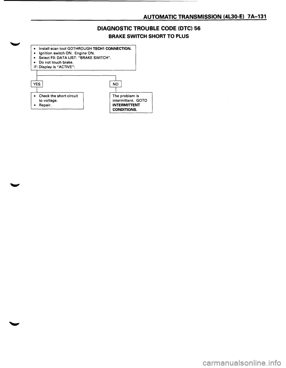
BRAKE SWITCH SHORT TO PLUS
• Install scan tool GOTH ROUGH TECH1 CONNECTION.
• Ignition switch ON. Engine ON.
• Select FO: DATA LIST: uBRAKE SWITCH".
•
Do not touch brake. IF: Display is uACTIVEu:
•
Check the short circuit
to voltage.
•
Repair. The
problem is
intermittent. GOTO
INTERMITTENT CONDITIONS.
Page 1004 of 1928
7A-132 AUTOMATIC TRANSMISSION (4L30-E)
DIAGNOSTIC TROUBLE CODE (DTC) 61
GEAR ERROR
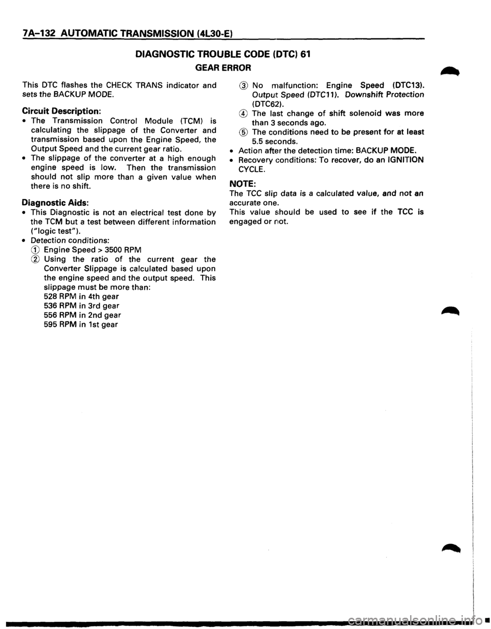
This DTC flashes the CHECK TRANS indicator and
sets the BACKUP MODE.
Circuit Description:
• The Transmission Control Module (TCM) is
calculating the slippage of the Converter and
transmission based upon the Engine Speed, the
Output Speed and the current gear ratio.
• The slippage of the converter at a high enough
engine speed is low. Then the transmission
should not slip more than a given value when
there is no shift.
Diagnostic Aids:
• This Diagnostic is not an electrical test done by
the TCM but a test between different information
("logic test").
• Detection conditions:
CD Engine Speed > 3500 RPM
@ Using the ratio of the current gear the
Converter Slippage is calculated based upon
the engine speed and the output speed. This
slippage must be more than:
528
RPM in 4th gear
536 RPM in 3rd gear
556 RPM in 2nd gear
595 RPM in 1st gear
@ No malfunction: Engine Speed (DTC13).
Output Speed (DTC11 ). Downshift Protection
(DTC62).
@ The last change of shift solenoid was more
than 3 seconds ago.
® The conditions need to be present for at least
5.5 seconds.
• Action after the detection time: BACKUP MODE.
•
Recovery conditions: To recover, do an IGNITION
CYCLE.
NOTE:
The TCC slip data is a calculated value, and not an
accurate one.
This value should be used to see if the TCC is
engaged or not.
•
Page 1005 of 1928
AUTOMATIC TRANSMISSION (4L30-E) 7 A-133
DIAGNOSTIC TROUBLE CODE (DTC) 61
GEAR ERROR
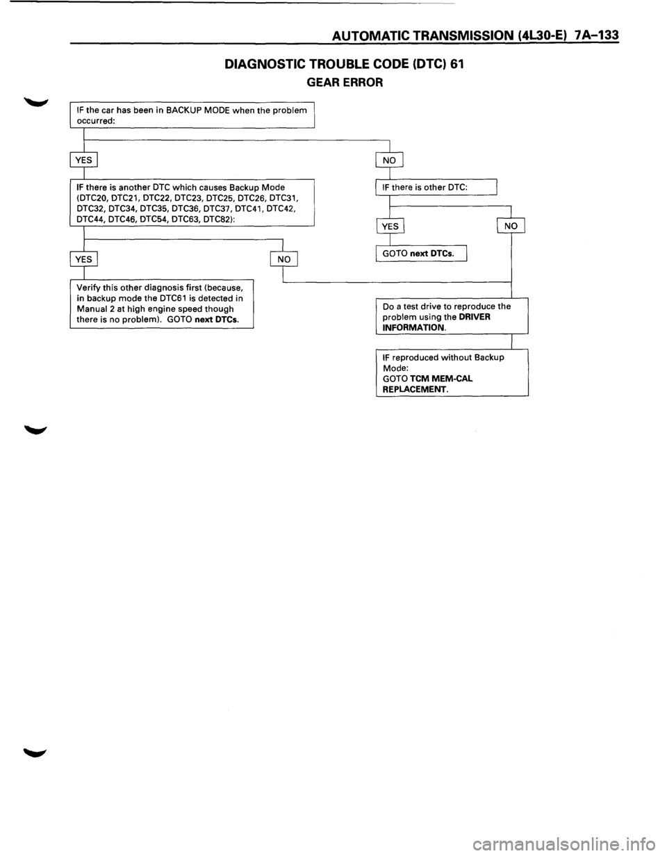
IF the car has been in BACKUP MODE when the problem occurred:
IF there is another DTC which causes Backup Mode (DTC20, DTC21, DTC22, DTC23, DTC25, DTC26, DTC31,
DTC32, DTC34, DTC35, DTC36, DTC37, DTC41, DTC42,
DTC44, DTC46, DTC54, DTC63, DTC82):
Verify this other diagnosis first (because,
in backup mode the
DTC61 is detected in Manual 2 at high engine speed though there is no problem). GOTO next DTCs.
Do a test drive to reproduce the problem using the DRIVER
INFORMATION.
IF reproduced without Backup
Mode:
GOTO TCM MEM-CAL
REPLACEMENT.