automatic transmission ISUZU TROOPER 1995 Workshop Manual
[x] Cancel search | Manufacturer: ISUZU, Model Year: 1995, Model line: TROOPER, Model: ISUZU TROOPER 1995Pages: 1928
Page 1006 of 1928
7A-134 AUTOMATIC TRANSMISSION (4L30-E)
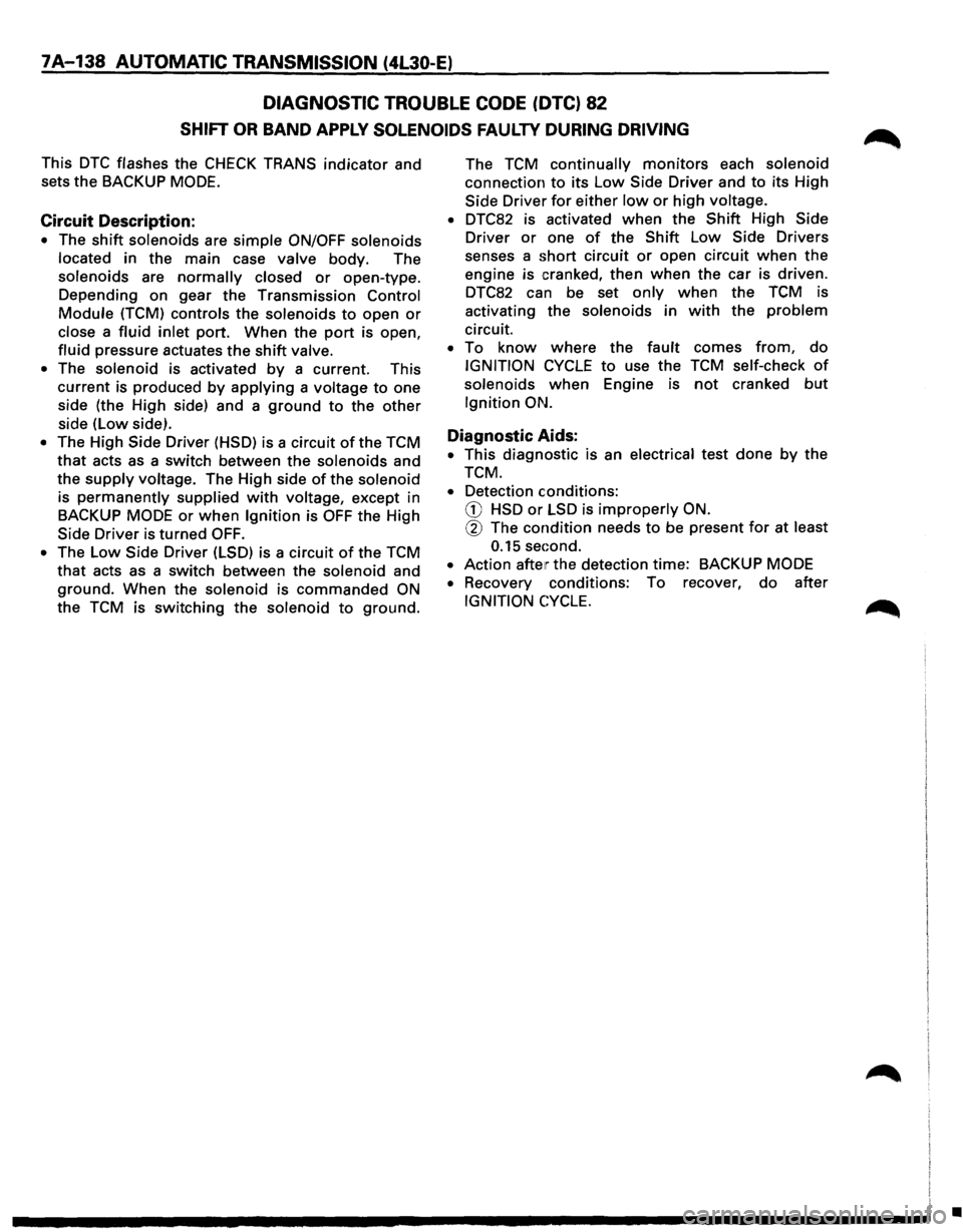
DIAGNOSTIC TROUBLE CODE (DTC) 62
DOWNSHIFT PROTECTION
This DTC flashes the CHECK TRANS indicator and
sets the
BACKUP MODE.
Circuit Description:
• The output speed information is used to
determine if the transmission has to upshift or
downshift.
• If this information suddenly changes due to an
open circuit or some electrical interference the
transmission
would downshift.
• To avoid this the Transmission Control Module
(TCM) is constantly checking the variations of the
Output Speed. If this variation is too great (too
much decrease
or increase) DTC62 is set. This
variation is taken into
amount only when the
output speed is more than : 90 KPH.
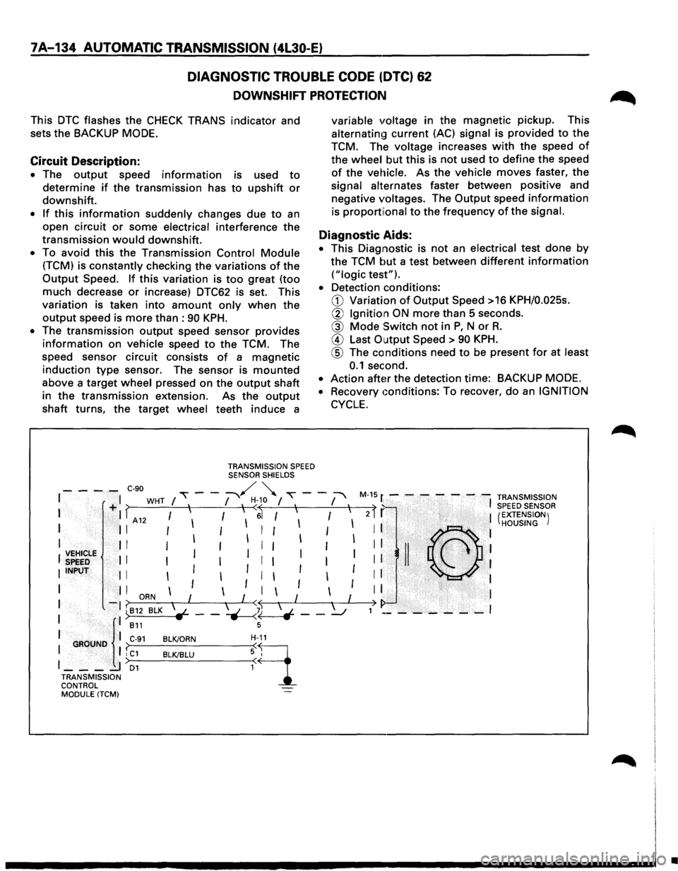
• The transmission output speed sensor provides
information on vehicle speed to the TCM. The
speed sensor circuit consists
of a magnetic
induction
type sensor. The sensor is mounted
above a target wheel pressed on the output shaft
in the transmission extension. As the
output
shaft turns, the target wheel teeth induce a
TRANSMISSION SPEED SENSOR SHIELDS
variable voltage in the magnetic pickup. This
alternating current (AC) signal is provided to the
TCM. The
voltage increases with the speed of
the wheel but this is not used to define the speed
of the vehicle. As the vehicle moves faster, the
signal alternates faster between positive and
negative
voltages. The Output speed information
is proportiional to the frequency of the signal.
Diagnostic Aids:
• This Diagnostic is not an electrical test done by
the TCM but a test between different information
("logic test").
• Detection conditions:
G) Variation of Output Speed >16 KPH/0.025s.
@ Ignition ON more than 5 seconds.
@ Mode Switch not in P, N or R.
@ Last Output Speed > 90 KPH.
@ The conditions need to be present for at least
0.1 second.
• Action after the detection time: BACKUP MODE.
•
Recovery Gonditions: To recover, do an IGNITION
CYCLE.
- - - -C-90 / " I ,---:-"'\. '-. ~---+I WHT I I I I ~-10 I 'I I 'I M-1
5 r - - - - - - -TRANSMISSION ) f I SPEED SENSOR I . I f A 12 I I I I ~ I I I I
I II I I I I I I I I I
I II I I I I 1 I I
~~~~rie II I Ill I I
IINPUT II I I I I
1 1 1 I l I I I I -? ORN I I < I I
I l: ):~~ BLK \~ __ ~~ __ ~
I GROUNO I C-91 BLK/ORN H-11
I I I C1 BLK/BLU ~ 9_ I ____ I D1
TRANSMISSION
CONTROL MODULE (TCM)
2 I I (EXTENSION)
: : .·(C},h.·.. ,.·, .. ·.,· .. : HOUSING
II II ·<;',~ . I
I I . 'I ' . . I
I I I
) I> 1 ________ I
•
Page 1007 of 1928
AUTOMATIC TRANSMISSION (4l30-E) 7 A .... 135
DIAGNOSTIC TROUBLE CODE (DTC) 62
DOWNSHIFT PROTECTION
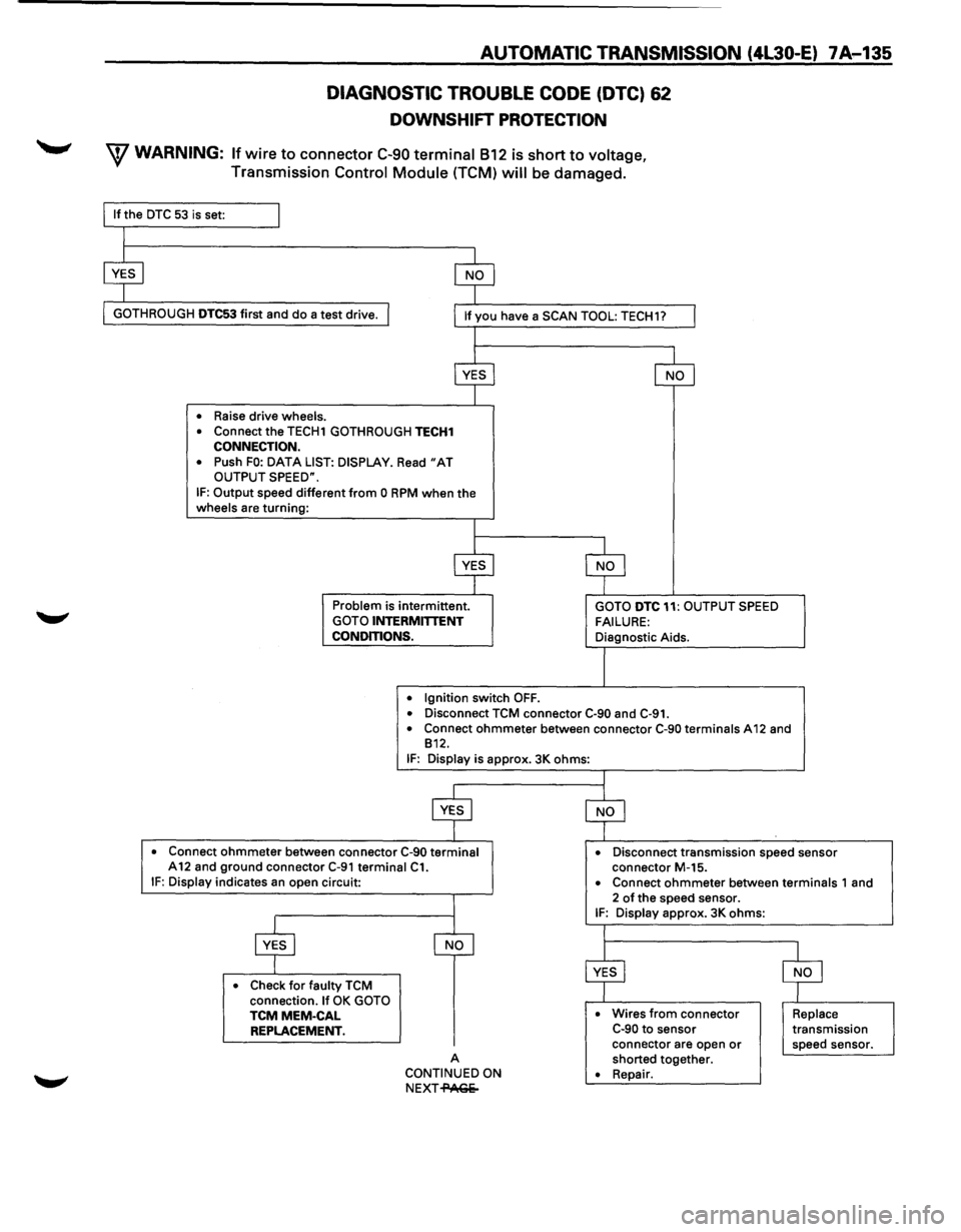
W WARNING: If wire to connector C-90 terminal 812 is short to voltage,
Transmission Control Module (TCM) will be damaged.
GOTH ROUGH DTC53 first and do a test drive.
• Raise drive wheels.
•
Connect the TECH1 GOTHROUGH TECH1 CONNECTION.
•
Push FO: DATA LIST: DISPLAY. Read "AT OUTPUT SPEED".
IF: Output speed different from 0 RPM when the wheels are turning:
Problem is intermittent. GOTO INTERMITTENT
CONDITIONS.
•
Ignition switch OFF.
GOTO DTC 11: OUTPUT SPEED
FAILURE: Diagnostic Aids.
• Disconnect TCM connector C·90 and C-91. • Connect ohmmeter between connector C-90 terminals A 12 and
812.
IF: Display is approx. 3K ohms:
• Connect ohmmeter between connector C-90 terminal A12 and ground connector C-91 terminal C1. • Disconnect transmission speed sensor
connector M-15.
IF: Display indicates an open circuit:
• Check for faulty TCM
connection. If OK GOTO TCMMEM-CAL REPLACEMENT.
A
CONTINUED ON
NEXT-PAGe- •
Connect ohmmeter between terminals 1
and
2 of the speed sensor. IF: Display approx. 3K ohms:
• Wires from connector C-90 to sensor
connector are open or shorted together. • Repair.
Replace transmission
speed sensor.
Page 1008 of 1928
7A-136 AUTOMATIC TRANSMISSION (4l30-E)
DIAGNOSTIC TROUBLE CODE (DTC) 62
DOWNSHIFT PROTECTION
(CONTINUED)
CONTINUED FROM
PREVIOUS PA(;Ii
A
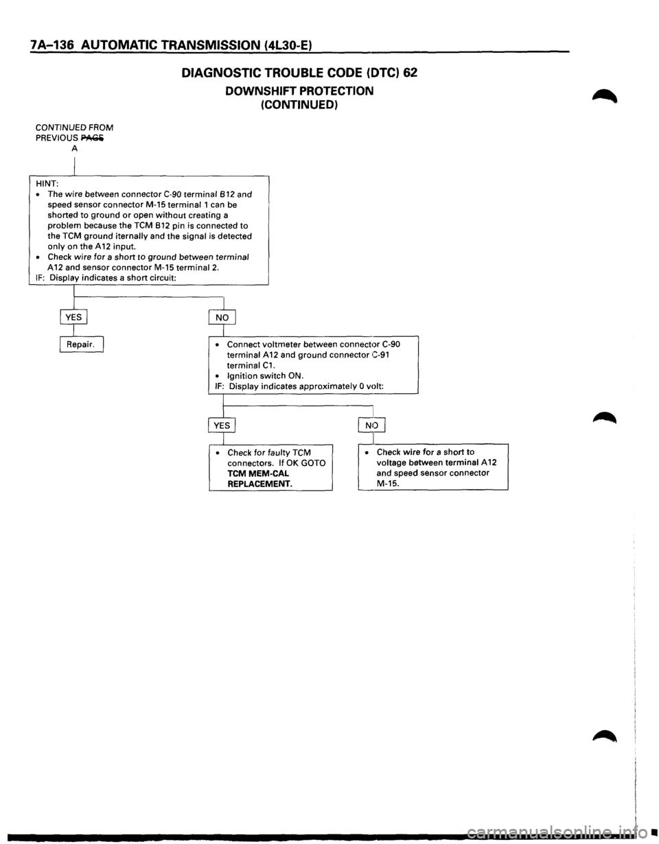
HINT:
•
The wire between connector C-90 terminal 812 and
speed sensor connector M-15 terminal 1 can be
shorted
to ground or open without creating a problem because the TCM 812 pin is connected to the TCM ground iternally and the signal is detected only on the A 12 input. • Check wire for a short to ground between terminal
A12 and sensor connector M-15 terminal 2. IF: Display indicates a short circuit:
• Connect voltmeter between connector C-90 terminal A 12 and ground connector C-91
terminal C1. • Ignition switch ON. IF: Display indicates approximately 0 volt:
• Check
for faulty TCM connectors. If OK GOTO TCMMEM-CAL REPLACEMENT.
• Check wire for a short to voltage between terminal A12
and speed sensor connector
M-15.
•
Page 1009 of 1928
AUTOMATIC TRANSMISSION (4L30-E) 7A-137
DIAGNOSTIC TROUBLE CODE (DTC) 63
EPROM CSUM FAILURE
This DTC flashes the CHECK TRANS indicator and
sets
the BACKUP MODE.
Circuit Description:
• The Erasable Programmable Read Only Memory
(EPROM) is an electronic circuit that contains the
commands that control the Transmission Control
Module (TCM).
•
The EPROM content is checked automatically
approx. each second by the TCM. This is called
Check
Sum (CSUM) calculation. If this CSUM is
false
this means that one command is altered.
• This can be due to a circuit failure or a bad
contact between the EPROM and
the TCM and
the
DTC63 will be set.
• If all EPROM connections are bad, the TCM does
not work. The CSUM can not be calculated and
detected.
Nothing works, not even the CHECK
TRANS
indicator.
Diagnostic Aids:
• This Diagnostic is not an electrical test done by
the TCM but a test between different information
("logic test").
• Detection conditions:
G) Bad EPROM Check Sum.
@ The condition needs to be present for at least
approx. 1 second.
• Action after the detection time: BACKUP MODE.
• Recovery conditions: To recover, do an IGNITION
CYCLE.
To Solve the Problem
• Check the EPROM MEM-CAL connector.
• If condition still exists, replace MEM-CAL.
Page 1010 of 1928
7A-138 AUTOMATIC TRANSMISSION (4L30-E)
DIAGNOSTIC TROUBLE CODE (DTC) 82
SHIFT OR BAND APPLY SOLENOIDS FAULTY DURING DRIVING
This DTC flashes the CHECK TRANS indicator and
sets
the BACKUP MODE.
Circuit Description:
• The shift solenoids are simple ON/OFF solenoids
located in the main case valve body. The
solenoids are
normally closed or open-type.
Depending
on gear the Transmission Control
Module (TCM) controls the solenoids to open or
close a fluid inlet port. When the port is open,
fluid pressure actuates the shift valve.
• The solenoid is activated by a current. This
current is produced by applying a voltage to one
side (the High side) and a
ground to the other
side (low side).
• The High Side Driver (HSD) is a circuit of the TCM
that acts as a switch between the solenoids and
the
supply voltage. The High side of the solenoid
is
permanently supplied with voltage, except in
BACKUP
MODE or when Ignition is OFF the High
Side Driver is turned
OFF.
• The Low Side Driver (LSD) is a circuit of the TCM
that acts as a switch between the solenoid and
ground. When the solenoid is commanded ON
the TCM is switching the solenoid to ground. The
TCM
continually monitors each solenoid
connection
to its Low Side Driver and to its High
Side Driver
for either low or high voltage.
• DTC82 is activated when the Shift High Side
Driver
or one of the Shift Low Side Drivers
senses a
short circuit or open circuit when the
engine is cranked, then when the car is driven.
DTC82 can be set
only when the TCM is
activating the solenoids in
with the problem
circuit.
• To know where the fault comes from, do
IGNITION CYCLE to use the TCM self-check of
solenoids when Engine is not cranked but
Ignition ON.
Diagnostic Aids:
• This diagnostic is an electrical test done by the
TCM.
• Detection conditions:
CD HSD or LSD is improperly ON.
@ The condition needs to be present for at least
0.15 sec:ond.
•
Action after the detection time: BACKUP MODE
•
Recovery conditions: To recover, do after
IGNITION CYCLE.
•
Page 1011 of 1928
AUTOMATIC TRANSMISSION (4L30-E) 7A-139
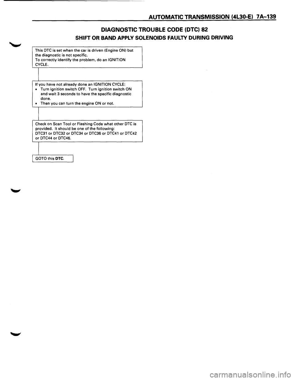
DIAGNOSTIC TROUBLE CODE (DTC) 82
SHIFT OR BAND APPLY SOLENOIDS FAULTY DURING DRIVING
This DTC is set when the car is driven (Engine ON) but the diagnostic is not specific.
To correctly identify the problem, do an IGNITION
CYCLE.
I
If you have not already done an IGNITION CYCLE:
• Turn ignition switch OFF. Turn ignition switch ON
and wait 3 seconds to have the specific diagnostic
done.
• Then you can turn the engine ON or not.
I
Check on Scan Tool or Flashing Code what other DTC is
provided. It should be one of the following: DTC31 or DTC32 or DTC34 or DTC36 or DTC41 or DTC42 or DTC44 or DTC46.
I
GOTO this DTC. I
Page 1012 of 1928
7A-140 AUTOMATIC TRANSMISSION (4L30-E)
WITHOUT DTC SET
1. If you have already checked the Diagnostic
Trouble Code (DTC) and the scan tool TECH1
does not provide any DTC, and you have
reproduced the
problem and no DTC was
stored:
This means that you have
to check the problem
by comparing the way it should work to the
way it works now that the problem exits.
2. To find the problem, perform the following
tests:
• A/TOil Temperature Indicator Test
• Transmission Operating Mode Test
•
Page 1013 of 1928
AUTOMATIC TRANSMISSION (4L30-E) 7A-141
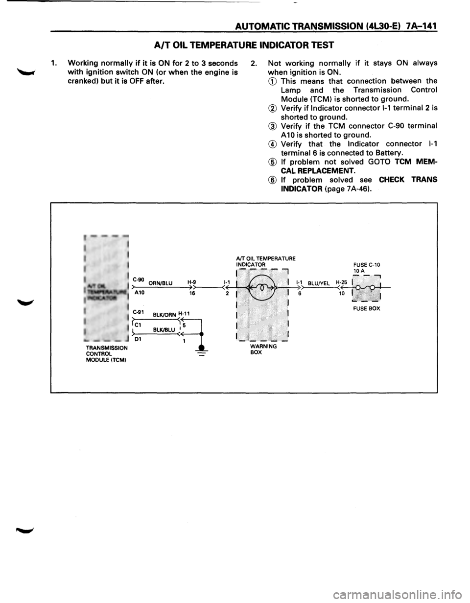
A/T OIL TEMPERATURE INDICATOR TEST
1. Working normally if it is ON for 2 to 3 seconds
with ignition switch ON (or when the engine is
cranked)
but it is OFF after.
2. Not working normally if it stays ON always
when ignition is ON.
CD This means that connection between the
Lamp and the Transmission
Control
Module (TCM) is shorted to ground.
r~,··mm -,-,~
• , I
I
TRANSMISSION
CONTROL
MODULE (TCM)
@ Verify if Indicator connector 1-1 terminal 2 is
shorted
to ground.
@ Verify if the TCM connector C-90 terminal
A10 is shorted to ground.
@ Verify that the Indicator connector 1-1
terminal 6 is connected to Battery.
@ If problem not solved GOTO TCM MEM
CAL REPLACEMENT.
@ If problem solved see CHECK TRANS
INDICATOR
(page 7A-46).
AfT OIL TEMPERATURE INDICATOR ~-~--~I
C-90 ORNJBLU H-9 1~1 :·' ,.· . 'I 1-1 >-A-10--=.:..;.;_;:,=-~>>----<( · , . ' >• • _;__I ;:. 16 2 1 . • .i· ,..:., • 6
I ·•'I• ·. . , . . J
BLU!YEL
BLKJORND
BLK/IILU ~~
I II 1
I I
1_:1;_-:....... _]
WARNING BOX
FUSE BOX
Page 1014 of 1928
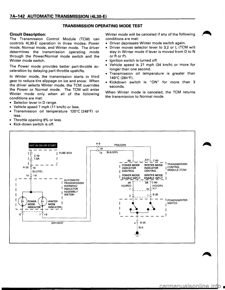
7A-142 AUTOMATIC TRANSMISSION (4l30-E)
TRANSMISSION OPERATING MODE TEST
Circuit
Description:
The Transmission Control Module (TCM) can
controls 4L30-E operation in three modes: Power
mode, Normal mode, and Winter mode. The driver
determines the transmission operating mode
through the Power/Normal mode switch and the
Winter mode switch.
The
Power mode provides better part-throttle ac
celeration
by delaying part-throttle upshifts.
In Winter mode, the transmission starts in third
gear to reduce tire slippage on ice and snow. When
the driver selects Winter mode, the TCM overrides
the
Power or Normal mode. The TCM will enter
Winter mode only when all of the following
conditions are met:
• Selector lever in D range.
• Vehicle speed 7 mph ( 11 km/h) or less.
•
Transmission oil temperature 120°C (248°F) or
less.
•
Throttle opening 8% or less.
•
Kick-down switch is off.
Winter mode will be canceled if any of the following
conditions are met:
• Driver depresses Winter mode switch again.
• Driver moves selector lever to 3,2 or L (TCM will
stay in Winter mode if lever is moved from D to N
orR or P).
• Ignition switch is turned off.
• Vehicle speed is 21 mph (34 km/h) or more for
longer than one second.
• Transmission oil temperature is greater than
140°C (284·°F).
• Kickdown switch is "ON" for more than 3
seconds.
When Winter mode is canceled, the TCM returns
the transmission
to Normal mode.
HOT IN ON OR START H-9 PNK/GRN
.«19 u
'1----~ FUSEBOX C-10 I 7.5A I
I
____ J
H-25 v 10
lBLUIYEL
14 1-9
r--- - - --AUTOMATIC
I
I I TRANSMISSION
WARNING/
I INDICATOR I ASSEMBLY (METER)
I
I WINTER MODE _INOICATORJ
GRY/WHT
«~13~-BL-K/~G-R-N----]
89 - - -~ 11 C-90
I~POW'ERMOOE-WiNTER MODE 1 TRANSMISSION
INDICATOR INDICATOR I CONTROL I CONTROL CONTROL MODULE !TCMI
I POWER MODE WINTER MODE I _gN~~L[.!NPUT-E!:::J£-BLE INPUl.. I
88 r ----86 rC-90 VIO/RED VIO/GRN 7 16 H-7
3 t ----~ 1 B-30
--\~~~--:~~~~NTER
-T---~
};
•
Page 1015 of 1928
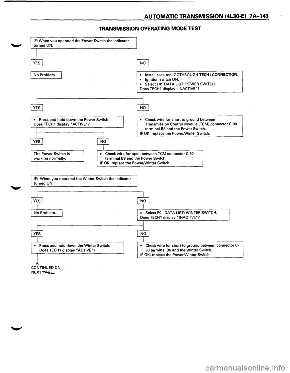
AUTOMATIC TRANSMISSION (4L30-E) 7A-143
TRANSMISSION OPERATING MODE TEST
IF: When you operated the Power Switch the indicator
turned ON:
•
Press and hold down the Power Switch.
Does TECH1 display "ACTIVE"? •
Install
scan tool GOTHROUGH TECH1 CONNECTION.
• Ignition switch ON.
• Select FO: DATA LIST: POWER SWITCH.
Does TECH1 display "INACTIVE"?
•
Check wire for short to ground between
Transmission Control Module (TCM) connector C-90
terminal
88 and the Power Switch.
IF OK, replace the Power/Winter Switch.
working
normally. •
Check wire for open
between TCM connector C-90
terminal 88 and the Power Switch. IF OK, replace the Power/Winter Switch.
IF: When you operated the Winter Switch the indicator
turned ON:
•
Press and hold down the Winter Switch.
Does TECH1 display "ACTIVE"?
A CONTINUED ON
NEXT~
DATA LIST: WINTER SWITCH.
•
Check wire for short to ground between connector C-90 terminal 86 and the Winter Switch. IF OK, replace the Power/Winter Switch.