4WD ISUZU TROOPER 1995 Workshop Manual
[x] Cancel search | Manufacturer: ISUZU, Model Year: 1995, Model line: TROOPER, Model: ISUZU TROOPER 1995Pages: 1928
Page 14 of 1928
OA-10 GENERAL INFORMATION
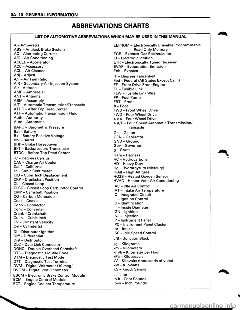
ABBREVIATIONS CHARTS
LIST OF AUTOMOTIVE ABBREVIATIONS WHICH MAY BE USED IN THIS MANUAL
A-Ampere(s)
ABS-Anti lock Brake System
AC-Alternating Current
A/C-Air Conditioning
ACCEL-Accelerator
ACC-Accessory
ACL-Air Cleaner
Adj-Adjust
A/F-Air Fuel Ratio
AIR-Secondary Air Injection System
Alt-Altitude
AMP-Ampere(s)
ANT-Antenna
ASM-Assembly
A/T-Automatic Transmission/Transaxle
ATDC-After Top Dead Center
ATF-Automatic Transmission Fluid
Auth -Authority
Auto -Automatic
BARO-Barometric Pressure
Bat -Battery
B+-Battery Positive Voltage
Bbl-Barrel
BHP-Brake Horsepower
BPT-Backpressure Transducer
BTDC-Before Top Dead Center
oc-Degrees Celsius
CAC-Charge Air Cooler
Calif-California
cc-Cubic Centimeter
CID-Cubic Inch Displacement
CKP-Crankshaft Position
CL-Closed Loop
CLCC-Closed Loop Carburetor Control
CMP-Camshaft Position
CO-Carbon Monoxide
Coax-Coaxial
Conn-Connector
Conv -Converter
Crank-Crankshaft
Cu.ln.-Cubic Inch
CV-Constant Velocity
Cyl-Cylinder(s)
Dl -Distributor Ignition
Diff-Differential
Dist-Distributor
DLC-Data Link Connector
DOHC-Double Overhead Camshaft
DTC-Diagnostic Trouble Code
DTM-Diagnostic Test Mode
DTT-Diagnostic Test Terminal
DVM-Digital Voltmeter (10 meg.)
DVOM-Digital Volt Ohmmeter
EBCM-Electronic Brake Control Module
ECM-Engine Control Module
ECT-Engine Coolant Temperature
EEPROM -Electronically Erasable Programmable
Read Only Memory
EGR-Exhaust Gas Recirculation
El-Electronic Ignition
ETR-Electronically Tuned Receiver
EVAP-Evaporation Emission
Exh-Exhaust
°F-Degrees Fahrenheit
Fed -
Federal (All States Except Calif.)
FF-Front Drive Front Engine
FL-Fusible Link
FLW-Fusible Link Wire
FP-Fuel Pump
FRT-Front
ft-Foot
FWD-Front Wheel Drive
4WD-Four Wheel Drive
4 x
4-Four Wheel Drive
4 A/T-Four Speed Automatic Transmission/
Transaxle
Gal-Gallon
GEN-Generator
GND-Ground
Gov-Governor
g-Gram
Harn -Harness
HC-Hydrocarbons
HD-Heavy Duty
Hg-Hydrargyrum (Mercury)
HiAit-High Altitude
H02S - Heated Oxygen Sensor
HVAC-Heater-Vent-Air Conditioning
lAC-Idle Air Control
IAT -Intake Air Temperature
IC-Integrated Circuit
-
Ignition Control
ID-Identification
-Inside Diameter
IGN-Ignition
INJ-Injection
IP-Instrument Panel
IPC-Instrument Panel Cluster
lnt-Intake
ISC-Idle Speed Control
J/B-Junction Block
kg -Kilograms
km-Kilometers
km/h -Kilometer per Hour
kPa-Kilopascals
kV-Kilovolts (thousands of volts)
kW-Kilowatts
KS -Knock Sensor
L-Liter
lb·ft-Foot Pounds
lb·in-Inch Pounds
Page 279 of 1928
FRONT DRIVING AXLE 4C-1
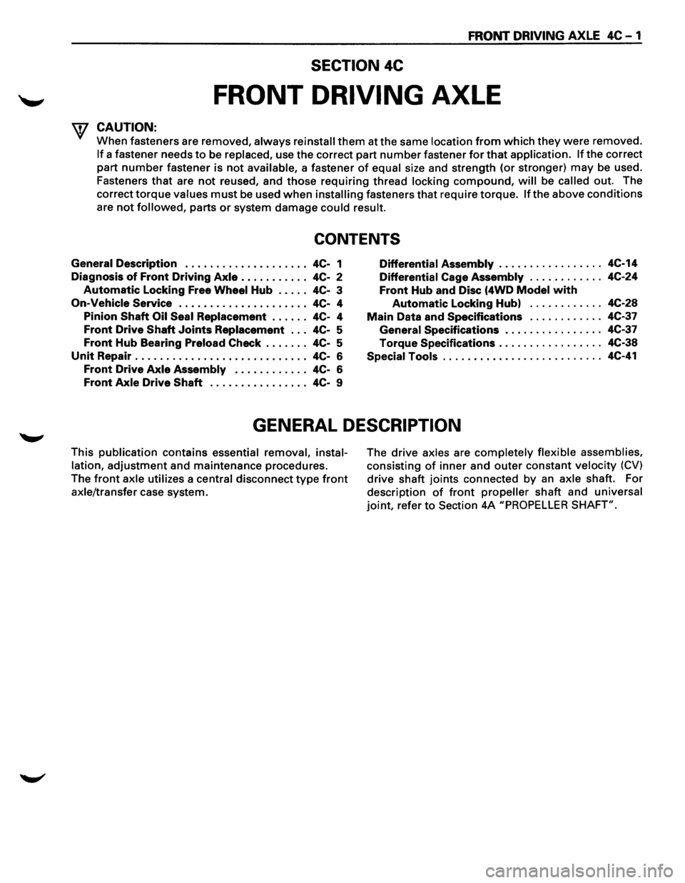
SECTION 4C
FRONT DRIVING AXLE
'f CAUTION:
When fasteners are removed, always reinstall them at the same location from which they were removed.
If a fastener needs to be replaced, use the correct part number fastener for that application. If the correct
part
number fastener is not available, a fastener of equal size and strength (or stronger) may be used.
Fasteners
that are not reused, and those requiring thread locking compound, will be called out. The
correct
torque values must be used when installing fasteners that require torque. If the above conditions
are not followed, parts or system damage could result.
CONTENTS
General Description . . . . . . . . . . . . . . . . . . . . 4C-1
Diagnosis
of Front Driving Axle . . . . . . . . . . . 4C-2
Automatic Locking Free Wheel Hub . . . . . 4C-3
On-Vehicle Service ..................... 4C- 4
Pinion
Shaft Oil Seal Replacement . . . . . . 4C-4
Front Drive Shaft Joints Replacement . . . 4C-5
Front Hub Bearing Preload Check . . . . . . . 4C-5
Unit Repair . . . . . . . . . . . . . . . . . . . . . . . . . . . . 4C-6
Front Drive Axle Assembly . . . . . . . . . . . . 4C-6
Front Axle Drive Shaft . . . . . . . . . . . . . . . . 4C-9
Differential Assembly ................. 4C-14
Differential Cage Assembly . . . . . . . . . . . . 4C-24
Front Hub and Disc (4WD Model with
Automatic Locking Hub) . . . . . . . . . . . . 4C-28
Main Data and Specifications . . . . . . . . . . . . 4C-37
General Specifications . .
. . . . . . . . . . . . . . 4C-37
Torque Specifications ................. 4C-38
Special Tools .......................... 4C-41
GENERAL DESCRIPTION
This publication contains essential removal, instal
lation,
adjustment and maintenance procedures.
The
front axle utilizes a central disconnect type front
axle/transfer case system. The
drive axles are completely flexible assemblies,
consisting
of inner and outer constant velocity (CV)
drive shaft joints connected by an axle shaft. For
description
of front propeller shaft and universal
joint, refer to Section 4A "PROPELLER SHAFT".
Page 306 of 1928
.
fi•28 FRONT DRIVINGk "
;: ~ ·~-¢,,
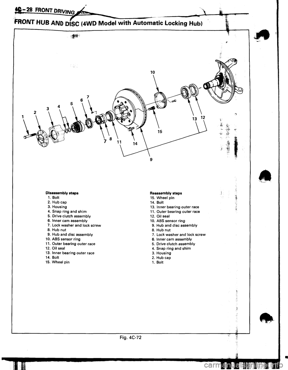
FRONT HUB AND D1SC (4WD Model with Automatic Locking Hub)
Disassembly steps 1. Bolt
2. Hub cap 3. Housing
4. Snap ring and shim
5. Drive clutch assembly 6. Inner cam assembly
7. Lock washer and lock screw 8. Hub nut
9. Hub and disc assembly 10. ABS sensor ring
11. Outer bearing outer race 12. Oil seal
13. Inner bearing outer race 14. Bolt
15. Wheel pin
Fig. 4C-72
10
9
Reassembly steps 15. Wheel pin 14. Bolt 13. Inner bearing outer race 11. Outer bearing outer race
12. Oil seal 10. ABS sensor ring 9. Hub and disc assembly 8. Hub nut 7. Lock washer and lock screw
6. Inner cam assembly 5. Drive clutch assembly 4. Snap ring and shim 3. Housing
2. Hub cap 1. Bolt
'
.f,
c. ' . .,;
)
t
~::
•
Page 315 of 1928
FRONT DRIVING AXLE 4C-37
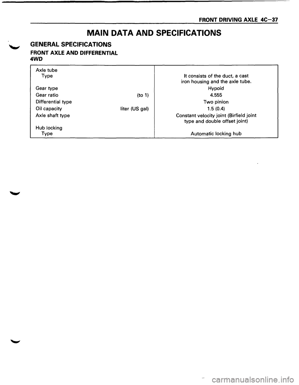
MAIN DATA AND SPECIFICATIONS
GENERAL SPECIFICATIONS
FRONT AXLE AND DIFFERENTIAL
4WD
Axle tube
Type
Gear type
Gear ratio
Differential type
Oil capacity
Axle shaft type
Hub locking
Type (to
1)
liter (US gal)
It consists of the
duct, a cast
iron housing and the axle tube.
Hypoid
4.555
Two pinion
1.5 (0.4)
Constant velocity joint (Birfield joint
type and double offset joint)
Automatic locking
hub
Page 374 of 1928
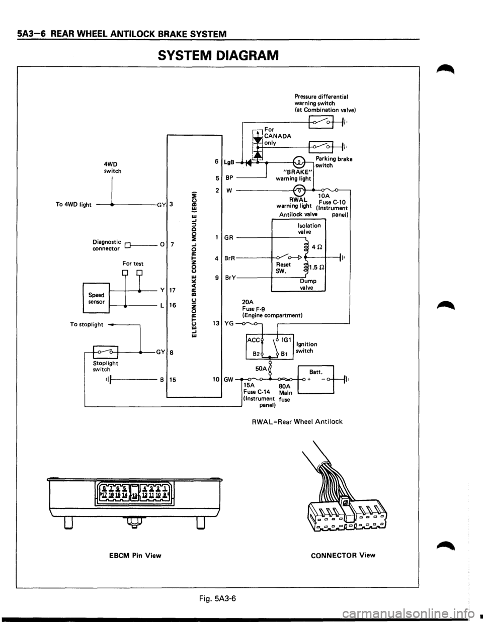
5A3-6 REAR WHEEL ANTILOCK BRAKE SYSTEM
SYSTEM DIAGRAM
4WD
switch
To 4WD
light -----11~-----lGY 3
Diagnostic Of------0 7 connector
For test
1-----11---+--y 17 Speed
sensor 1-----lt-----L
16
To
stoplight -----,
Stoplight switch
•IJI-----B 15
EBCM Pin View
i
&l ~ IU _, :;) Q
~ _, 0 a: .... z
8 IU ~ c( a: liD (.) z 0 a: 1-(.) IU _, IU
Pressure differential warning switch
(at Combination valve)
r-----+-<1 ~+II•
I•
6 LgB Parking brake _.-MI ____ ___,I'\.JI.Jr-, switch
5
BP -----'
2 w ------------~~._~
GR
4 BrR
9 BrY
20A Fuse F-9
RWAL 10
A •
1• h Fuse C-10
warnmg IQ t (Instrument
Antilock valve panel)
Isolation
valve
~ 4il .J o--1> ~
Reset ~1.5il
I
sw.
Dump valve
(Engine compartment)
13 YG -
82 81 switch
50 A
Batt.
10 GW + ,,
15A BOA Fuse C-14 Main (Instrument fuse panel)
RWAL=Rear Wheel Antilock
CONNECTOR View
Fig. 5A3-6
•
Page 385 of 1928
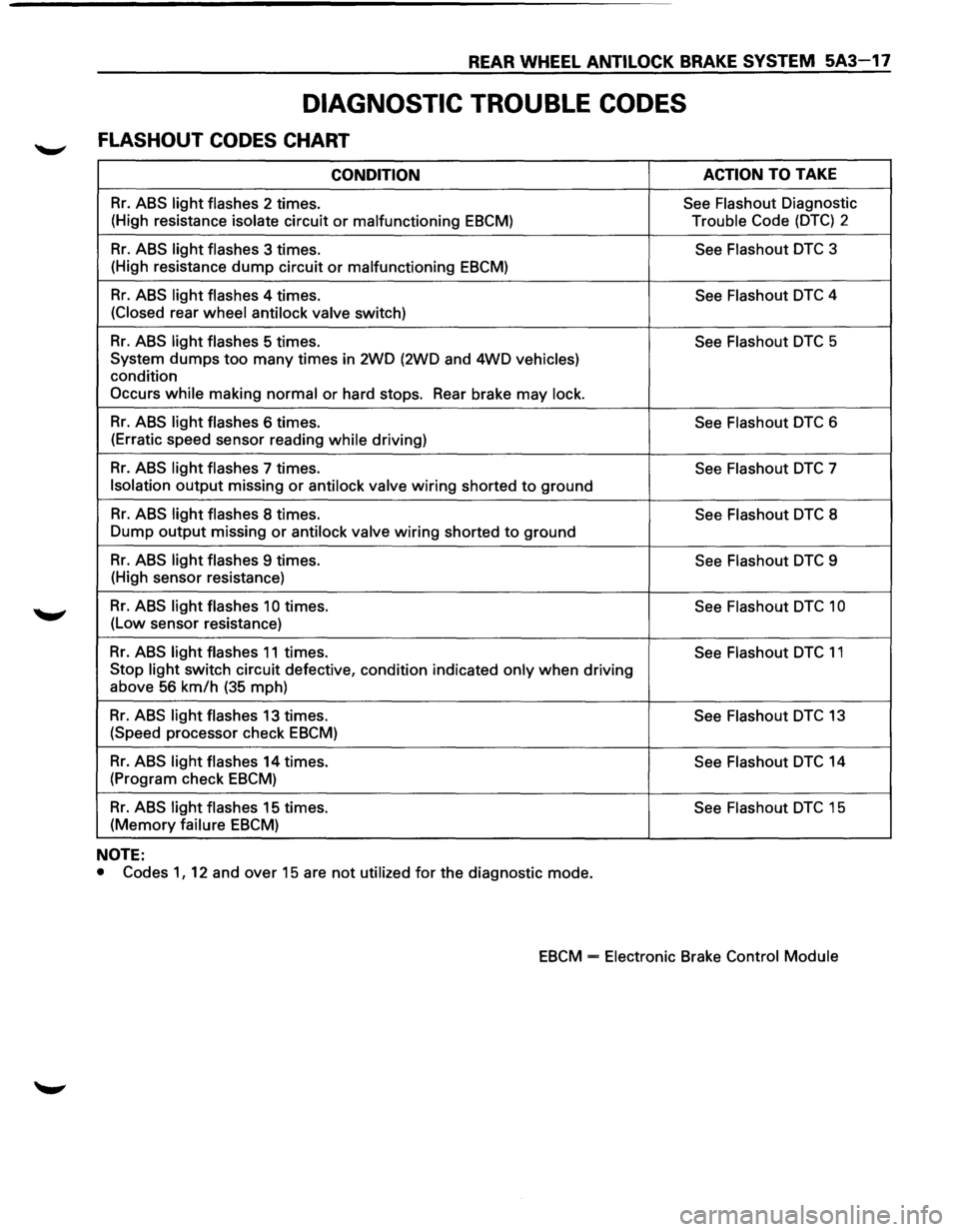
REAR WHEEL ANTILOCK BRAKE SYSTEM 5A3-17
DIAGNOSTIC TROUBLE CODES
FLASHOUT CODES CHART
CONDITION ACTION TO
TAKE
Rr. ABS light flashes 2 times. See Flashout Diagnostic
(High resistance
isolate circuit or malfunctioning EBCM) Trouble Code (DTC) 2
Rr. ABS light flashes 3 times. See Flashout DTC 3
(High resistance
dump circuit or malfunctioning EBCM)
Rr. ABS light flashes 4 times.
See Flashout DTC 4
(Closed rear wheel antilock valve switch)
Rr. ABS light flashes 5 times.
See Flashout DTC 5
System dumps
too many times in 2WD (2WD and 4WD vehicles)
condition
Occurs while making normal or hard stops. Rear brake may lock.
Rr. ABS light flashes 6 times.
See Flashout DTC 6
(Erratic speed sensor reading
while driving)
Rr. ABS light flashes 7 times. See Flashout DTC 7
Isolation output missing or antilock valve wiring shorted to ground
Rr. ABS light flashes 8 times.
See Flashout DTC 8
Dump
output missing or antilock valve wiring shorted to ground
Rr. ABS light flashes 9 times. See Flashout DTC 9
(High sensor resistance)
Rr. ABS light flashes 10 times.
See Flashout DTC 1 0
(Low sensor resistance)
Rr. ABS light flashes 11 times.
See Flashout DTC 11
Stop light switch circuit defective, condition indicated only when driving
above
56 km/h (35 mph)
Rr. ABS light flashes 13 times.
See Flashout DTC 13
(Speed processor check EBCM)
Rr. ABS light flashes 14 times.
See Flashout DTC 14
(Program check
EBCM)
Rr. ABS light flashes 15 times.
See Flashout DTC 15
(Memory failure EBCM)
NOTE:
• Codes 1, 12 and over 15 are not utilized for the diagnostic mode.
EBCM = Electronic Brake Control Module
Page 392 of 1928
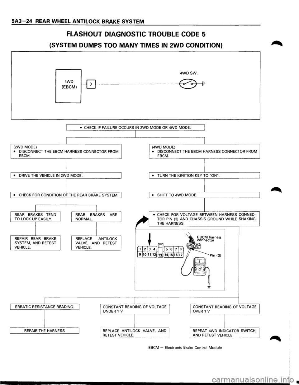
5A3-24 REAR WHEEL ANTILOCK BRAKE SYSTEM
FLASHOUT DIAGNOSTIC TROUBLE CODE 5
(SYSTEM DUMPS TOO MANY TIMES IN 2WD CONDITION)
4WD
(EBCM)
4WDSW.
I•
I • CHECK IF FAILURE OCCURS IN 2WD MODE OR 4WD MODE. I
I I (2WD MODE) (4WD MODE)
• DISCONNECT THE EBCM HARNESS CONNECTOR FROM • DISCONNECT THE EBCM HARNESS CONNECTOR FROM
EBCM. EBCM.
J I • DRIVE THE VEHICLE IN 2WD MODE. • TURN
THE IGNITION KEY TO "ON".
l I • CHECK FOR CONDITION OF THE REAR BRAKE SYSTEM. • SHIFT TO 4WD MODE.
I
I I I REAR BRAKES TEND REAR BRAKES ARE
~
• CHECK FOR VOLTAGE BETWEEN HARNESS CONNEC-
TO LOCK UP EASILY. NORMAL. TOR PIN (3) AND CHASSIS GROUND WHILE SHAKING
I I
THE HARNESS.
~ 1S
REPAIR REAR BRAKE REPLACE
ANTI LOCK EBCM harness
connector
SYSTEM, AND RETEST VALVE, AND
RETEST ·'"·. ~)l VEHICLE. VEHICLE. [1l21314l~ 5161718) .......
J9J1oJ11J12r13 14J15J1sJ 11] = Pin (3)
~-~\
~ -~~~
"!!'
ERRATIC RESISTANCE READING. I I CONSTANT READING OF VOLTAGE I I CONSTANT
READING OF VOLTAGE
UNDER 1 V OVER 1 V
REPAIR THE HARNESS I I REPLACE ANTILOCK VALVE, AND I I REPEAT 4WD INDICATOR
SWITCH, RETEST VEHICLE. AND RETEST VEHICLE.
EBCM
~ Electronic Brake Control Module
I
•
Page 412 of 1928
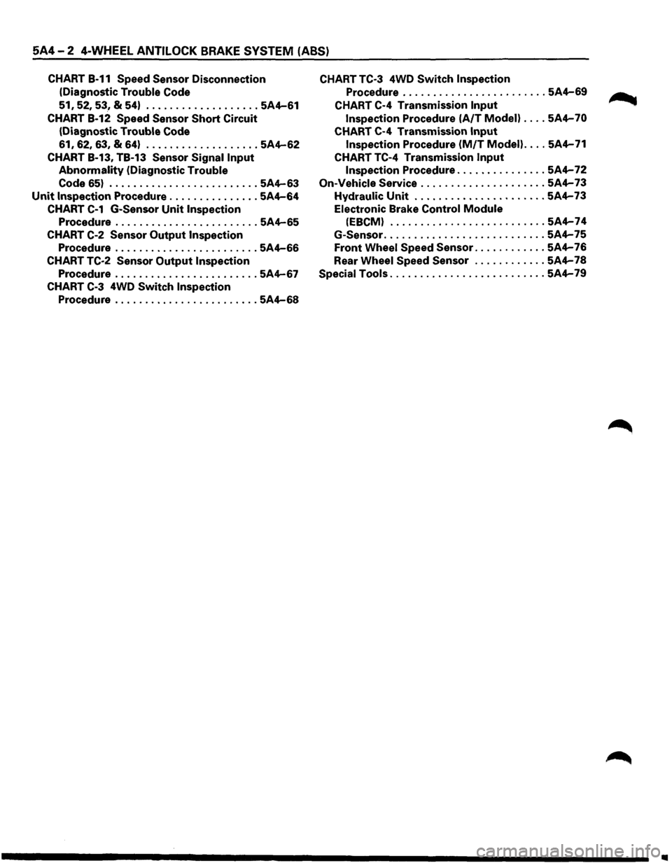
5A4-2 4-WHEEL ANTILOCK BRAKE SYSTEM (ABS)
CHART B-11 Speed Sensor Disconnection
(Diagnostic
Trouble Code
51, 52, 53, & 54) ................... 5A4-61
CHART B-12 Speed Sensor Short Circuit
(Diagnostic Trouble Code
61, 62,
63,
& 64) ................... 5A4-62
CHART B-13, TB-13 Sensor Signal Input
Abnormality (Diagnostic Trouble
Code
65) ......................... 5A4-63
Unit Inspection Procedure ............... 5A4-64
CHART C-1 G-Sensor Unit Inspection
Procedure ........................ 5A4-65
CHART C-2 Sensor Output Inspection
Procedure ........................ 5A4-66
CHART TC-2 Sensor Output Inspection
Procedure ........................ 5A4-67
CHART C-3 4WD Switch Inspection
Procedure ........................ 5A4-68
CHART TC-3 4WD Switch Inspection
Procedure ........................ 5A4-69
CHART C-4 Transmission Input
Inspection Procedure (A/T Modell .... 5A4-70
CHART C-4 Transmission Input
Inspection Procedure (M/T Model) .... 5A4-71
CHART TC-4 Transmission Input
Inspection Procedure ............... 5A4-72
On-Vehicle Service ..................... 5A4-73
Hydraulic Unit ...................... 5A4-73
Electronic Brake Control Module
(EBCMI .......................... 5A4-74
G-Sensor ........................... 5A4-75
Front Wheel Speed Sensor ............ 5A4-76
Rear
Wheel Speed Sensor ............ 5A4-78
Special Tools .......................... 5A4-79
..
Page 414 of 1928
5A4-4 4-WHEEL ANTILOCK BRAKE SYSTEM (ABS)
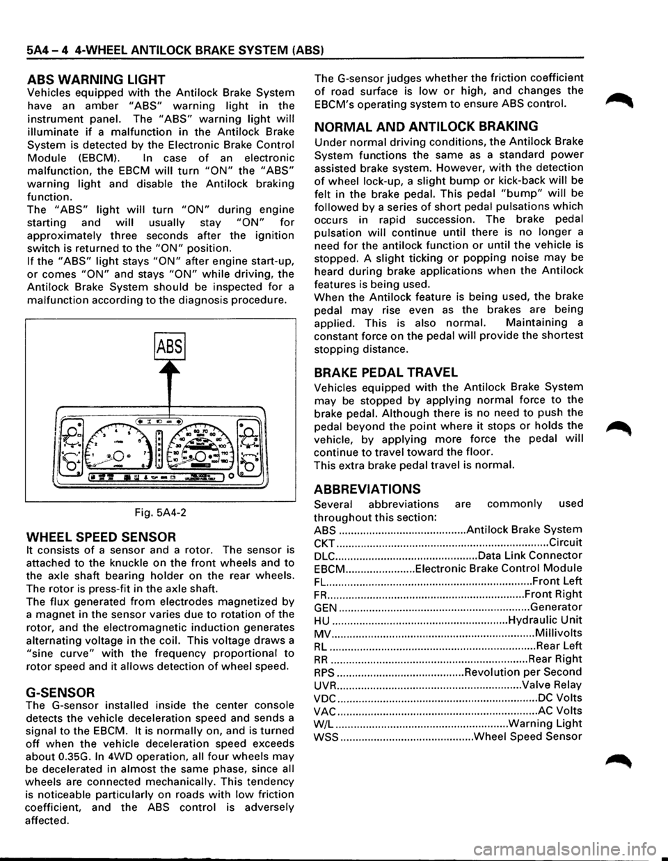
ABS WARNING LIGHT
Vehicles equipped with the Antilock Brake System
have an
amber "ABS" warning light in the
instrument panel. The "ABS" warning light will
illuminate if a malfunction in the Antilock Brake
System is detected by the Electronic Brake
Control
Module (EBCM). In case of an electronic
malfunction, the EBCM will turn "ON" the "ABS"
warning light and disable the Antilock braking
function.
The
"ABS" light will turn "ON" during engine
starting and
will usually stay "ON" for
approximately three seconds after the ignition
switch is returned to the "ON" position.
If the "ABS" light stays "ON" after engine start-up,
or comes "ON" and stays "ON" while driving, the
Antilock Brake System should be inspected
for a
malfunction according to the diagnosis procedure.
Fig. 5A4-2
WHEEL SPEED SENSOR
It consists of a sensor and a rotor. The sensor is
attached
to the knuckle on the front wheels and to
the axle shaft bearing holder on the rear wheels.
The
rotor is press-fit in the axle shaft.
The
flux generated from electrodes magnetized by
a magnet in the sensor varies due to rotation of the
rotor, and the electromagnetic
induction generates
alternating voltage in
the coil. This voltage draws a
"sine curve" with the frequency proportional to
rotor speed and it allows detection of wheel speed.
G-SENSOR
The G-sensor installed inside the center console
detects the vehicle deceleration speed and sends a
signal
to the EBCM. It is normally on, and is turned
off when the vehicle deceleration speed exceeds
about 0.35G.
In 4WD operation, all four wheels may
be decelerated in almost the same phase, since all
wheels are connected mechanically. This tendency
is noticeable particularly on roads
with low friction
coefficient, and the
ABS control is adversely
affected. The
G-sensor judges
whether the friction coefficient
of road surface is low or high, and changes the
EBCM's operating system to ensure ABS control.
NORMAL AND ANTILOCK BRAKING
Under normal driving conditions, the Antilock Brake
System functions the same
as a standard power
assisted brake system. However, with the detection
of wheel lock-up, a slight bump or kick-back will be
felt in the brake pedal. This pedal
"bump" will be
followed by a series of short pedal pulsations which
occurs in rapid succession. The brake pedal
pulsation
will continue until there is no longer a
need
for the antilock function or until the vehicle is
stopped. A
slight ticking or popping noise may be
heard
during brake applications when the Antilock
features is being used.
When the
Antilock feature is being used, the brake
pedal
may rise even as the brakes are being
applied. This is also
normal. Maintaining a
constant force on the pedal
will provide the shortest
stopping distance.
BRAKE PEDAL TRAVEL
Vehicles equipped with the Antilock Brake System
may be stopped by applying normal force to the
brake pedal.
Although there is no need to push the
pedal beyond the
point where it stops or holds the ~
vehicle, by applying more force the pedal will
continue to travel toward the floor.
This extra brake pedal travel is normal.
ABBREVIATIONS
Several abbreviations are commonly used
throughout this section:
ABS .......................................... Antilock Brake System
CKT ...................................................................... Circuit
DLC ............................................... Data Link Connector
EBCM ....................... Eiectronic Brake Control Module
FL. ................................................................... Front Left
FR ................................................................. Front Right
GEN ............................................................... Generator
HU .......................................................... Hydraulic Unit
MV ................................................................... Millivolts
RL .................................................................... Rear Left
RR ................................................................. Rear Right
RPS .......................................... Revolution per Second
UVR ............................................................. Valve Relay
VDC .................................................................. DC Volts
VAC .................................................................. AC Volts
W/L .........................................................
Warning Light
WSS ............................................ Wheel Speed Sensor
Page 418 of 1928
5A4-8 4-WHEEL ANTILOCK BRAKE SYSTEM (ABS)
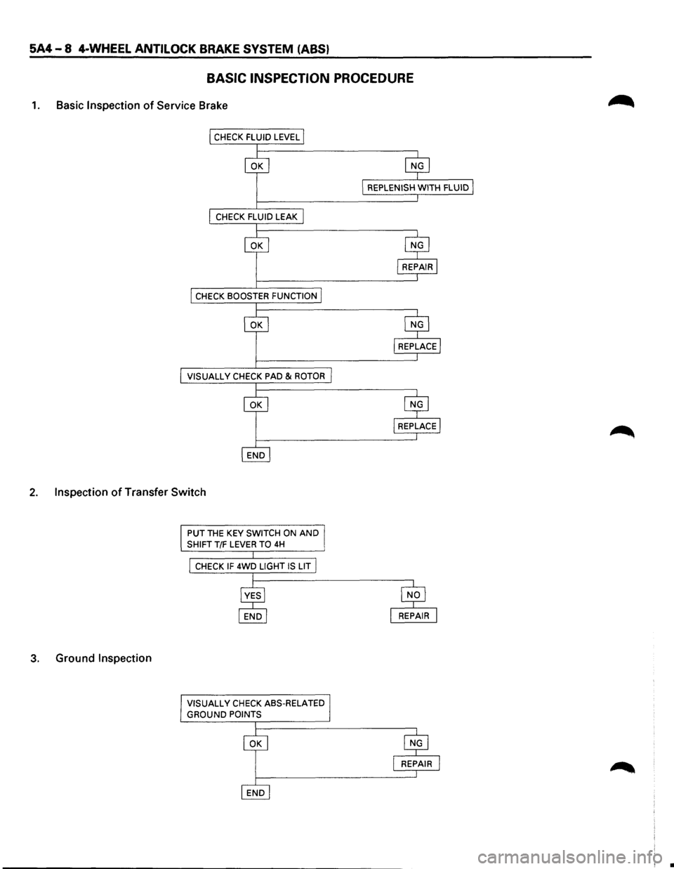
BASIC INSPECTION PROCEDURE
1. Basic Inspection of Service Brake
VISUALL V CHECK PAD & ROTOR
2. Inspection of Transfer Switch
3. Ground Inspection
PUT THE KEY SWITCH ON AND
SHIFT T/F LEVER TO 4H
CHECK IF 4WD LIGHT IS LIT
VISUALL
V CHECK ASS-RELATED
GROUND POINTS
•