catalytic converter ISUZU TROOPER 1995 User Guide
[x] Cancel search | Manufacturer: ISUZU, Model Year: 1995, Model line: TROOPER, Model: ISUZU TROOPER 1995Pages: 1928
Page 863 of 1928
ENGINE EXHAUST (V6 3.2L) 6F-1
SECTION 6F
ENGINE EXHAUST (V6 3.2L)
\fl CAUTION:
VI Exhaust system components must have enough clearance from the upderbody to prevent overheating the
floor pan and damaging the passenger compartment, insulation
and trim materials.
CONTENTS
General Description . . . . . . . . . . . . . . . . . . . . 6F,....1
Hangers ........................... , ... ..-6f-2
Three Way Catalytic Converter ....• ·; ~. 6F-2
Gasket . . . . . . . . . . . . . . . . . . . . . . . . . . . . . 6F-2
On-Vehicle Service ........ , . . . . . . . . . . . 6F-3
Front Exhaust Pipe ... , " ;< . . . . . . . . . . . . 6F-3
Center Exhaust Pipe.. .. : -. . . . . . . . . . . . . . . . 6F-4
.. .r·
Three Way Catalytic Converter . . . . . . . . . 6F-5
Pre Catalytic Converter . . . . . . . . . . . . . . . 6F-6
Exhaust Silencer . . . . . . . . . . . . . . . . . . . . . 6F-7
Rear Exhaust Pipe . . . . . . . . . . . . . . . . . . . . 6F-8
Exhaust Pipe Mounting Rubber . . . . . . . . 6F-9
Main Data and Specifications ........... 6F-10
Torque Specifications ............... 6F-10
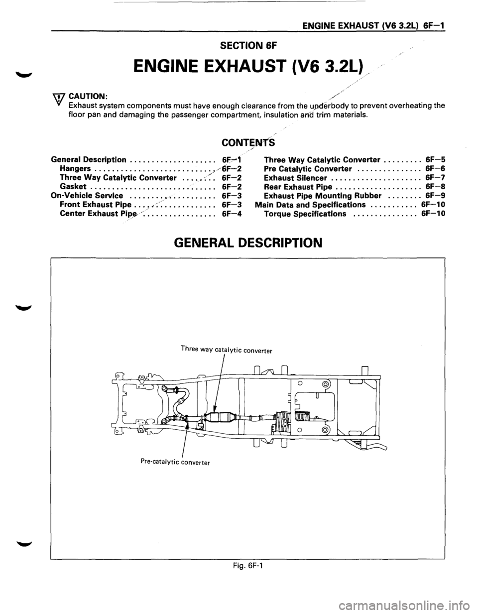
GENERAL DESCRIPTION
Three way catalytic converter
Pre-catalytic converter
Fig. 6F-1
Page 864 of 1928
6F-2 ENGINE EXHAUST (V6 3.2L)
When inspecting or replacing exhaust system
components, make sure there is adequate
clearance
from all points on the underbody to prevent over
heating the
floor pan and possible damage to the
passenger
compartment insulation and trim materials.
Check complete exhaust system and nearby body
areas and rear compartment lid for broken, damaged,
missing
or mispositioned parts, open seams, holes,
loose
connections or other deterioration which could
permit exhaust fumes to seep into the rear
compartment or passenger compartment. Dust or
water in the rear compartment may be an indication of
a problem in one of these areas. Any faulty areas
should be corrected immediately.
HANGERS
Various types of hangers are used to support exhaust
system(s). These
include conventional rubber straps,
rubber rings, and rubber
blocks.
The installation of exhaust system supports is very
important,
as improperly installed supports can cause
annoying vibrations
which can be difficult to diagnose.
THREE WAY CATAL VTIC CONVERTER
The three way catalytic converter is an emission
control device added to the exhaust system to reduce
pollutants from the exhaust gas stream.
W CAUTION:
VI • The catalytic converter requires the use of
unleaded fuel only.
Periodic
maintenance of the exhaust system is not
required. If the vehicle is raised for other service, it is
advisable to check the condition of the complete
exhaust system.
A
dual bed monolith catalytic converter is used in
combination
with three way catalytic converter.
Catalytic Types:
Three
way (Reduction/Oxidation) catalyst
The catalyst coating on the three way (reduction)
converter contains
platinum and rhodium which
lowers the levels of oxide of nitrogen (NOx) as well as
hydrocarbons (HC) and carbon monoxide (Co).
GASKET
The gasket must be replaced whenever a new exhaust
pipe,
muffler or catalytic converter is installed.
Page 866 of 1928
&F-4 ENGINE EXHAUST (V6 3.2L)
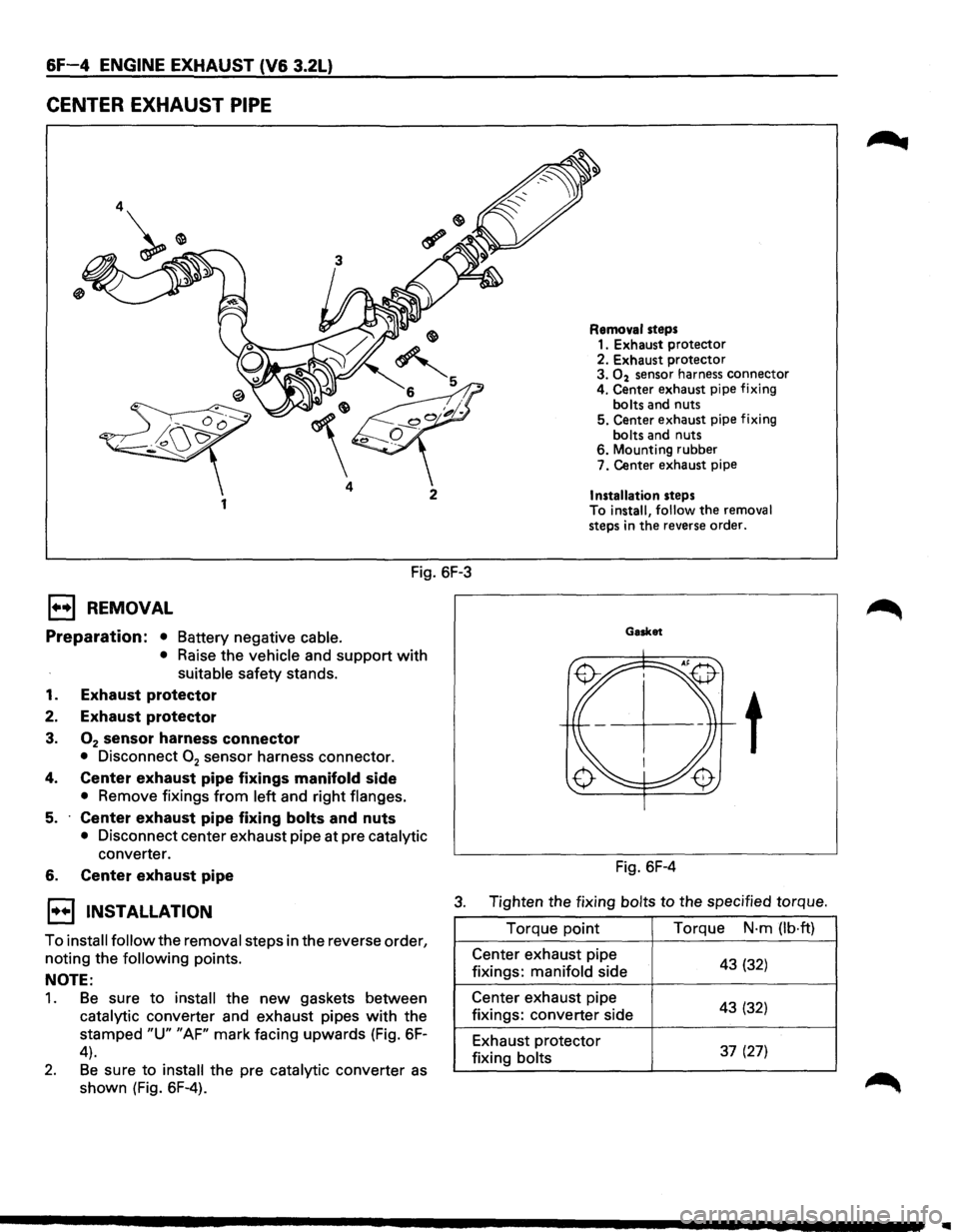
CENTER EXHAUST PIPE
4
1
Fig. 6F-3
E3 REMOVAL
Preparation: • Battery negative cable.
• Raise the vehicle and support with
suitable safety stands.
1. Exhaust protector
2. Exhaust protector
3. 02 sensor harness connector
• Disconnect 02 sensor harness connector.
4. Center exhaust pipe fixings manifold side
• Remove fixings from left and right flanges.
5. Center exhaust pipe fixing bolts and nuts
• Disconnect center exhaust pipe at pre catalytic
converter.
6. Center exhaust pipe
Removal steps 1. Exhaust protector
2. Exhaust protector
3.
02 sensor harness connector
4. Center exhaust pipe fixing
bolts and nuts
5. Center exhaust pipe fixing
bolts and nuts
6. Mounting rubber
7. Center exhaust pipe
Installation steps
To install, follow the removal
steps in the reverse order.
Gasket
t
Fig. 6F-4
1••1 INSTALLATION 3. Tighten the fixing bolts to the specified torque.
To
install follow the removal steps in the reverse order,
noting the
following points.
NOTE:
1. Be sure to install the new gaskets between
catalytic converter and exhaust pipes
with the
stamped
"U" "AF" mark facing upwards (Fig. 6F-
4).
2. Be sure to install the pre catalytic converter as
shown (Fig. 6F-4). Torque
point
Center exhaust pipe
fixings: manifold side
Center exhaust pipe
fixings: converter side
Exhaust protector
fixing bolts Torque
N·m
(lb·ft)
43 (32)
43 (32)
37 (27)
Page 867 of 1928
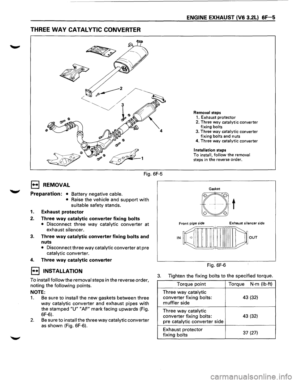
THREE WAY CATALYTIC CONVERTER
Fig. 6F-5
1••1 REMOVAL
Preparation: • Battery negative cable.
•
Raise the vehicle and support with
suitable safety stands.
1. Exhaust protector
2. Three way catalytic converter fixing bolts
• Disconnect three way catalytic converter at
exhaust
silencer.
3. Three way catalytic converter fixing bolts and
nuts
• Disconnect three way catalytic converter at pre
catalytic converter.
4. Three way catalytic converter
ENGINE EXHAUST (V6 3.2L) &F-5
Removal steps
1. Exhaust protector
2. Three way catalytic converter
fixing
bolts 3. Three way catalytic converter
fixing bolts and nuts
4. Three way catalytic converter
Installation steps
To
install, follow the removal steps in the reverse order.
Gasket
t
Front pipe side Exhaust silencer side
--;::;;;=;;:::;;=;;:::;;±:;;:~mn=i:'--
IN OUT
Fig. 6F-6
1••1 INSTALLATION
To install follow the removal steps in the reverse order,
noting the
following points.
3. Tighten the fixing bolts to the specified torque.
NOTE:
1. Be sure to install the new gaskets between three
way catalytic converter and exhaust pipes with
the stamped "U" "AF" mark facing upwards (Fig.
6F-6).
2. Be sure to install the three way catalytic converter
as shown (Fig. 6F-6). Torque
point
Three way catalytic
converter
fixing bolts:
muffler side
Three
way catalytic
converter fixing bolts:
pre catalytic converter side
Exhaust protector
fixing
bolts
Torque N·m (lb·ft)
43 (32)
43 (32)
37
(27)
Page 868 of 1928
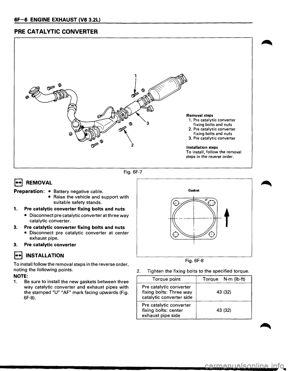
6F-6 ENGINE EXHAUST (V6 3.2L)
PRE CATAL VTIC CONVERTER
2
Fig. 6F-7
1••1 REMOVAL
Preparation: • Battery negative cable.
•
Raise the vehicle and support with
suitable safety stands.
1. Pre catalytic converter fixing bolts and nuts
• Disconnect pre catalytic converter at three way
catalytic converter.
3. Pre catalytic converter fixing bolts and nuts
• Disconnect pre catalytic converter at center
exhaust pipe.
3. Pre catalytic converter
1••1 INSTALLATION
Removal steps
1. Pre catalytic converter
fixing bolts and nuts
2. Pre catalytic converter
fixing bolts and
nuts 3. Pre catalytic converter
Installation steps To install, follow the removal
steps in the reverse order.
Gasket
t
Fig. 6F-8
To install follow the removal steps in the reverse order,
noting the following points. 2. Tighten the fixing bolts to the specified torque.
NOTE:
1. Be sure to install the new gaskets between three
way catalytic converter and exhaust pipes with
the stamped "U" "AF" mark facing upwards (Fig.
6F-8). Torque
point
Pre catalytic converter
fixing
bolts: Three way
catalytic converter side
Pre catalytic converter
fixing
bolts: center
exhaust pipe side Torque
N·m
(lb·ft)
43 (32)
43 (32)
Page 869 of 1928
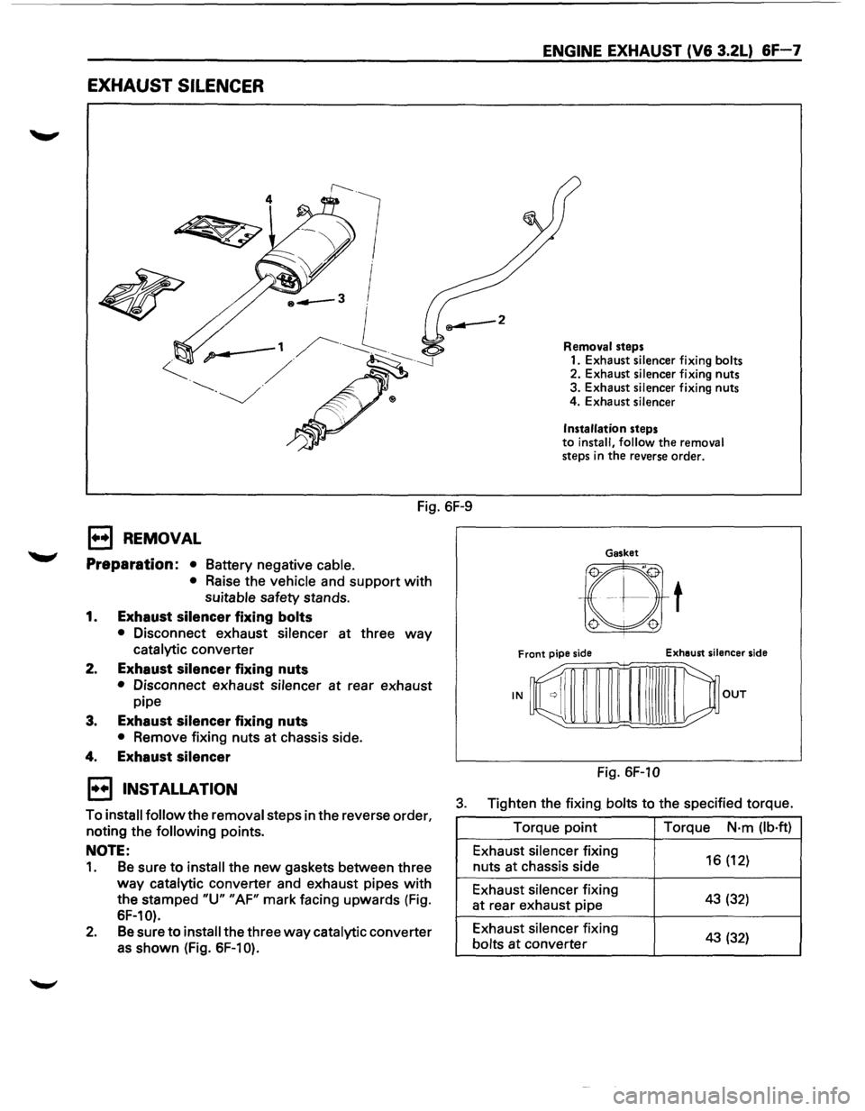
EXHAUST SILENCER
4
Fig. 6F-9
E) REMOVAL
Preparation: •
Battery negative cable.
• Raise the vehicle and support with
suitable safety stands.
1. Exhaust silencer fixing bolts
• Disconnect exhaust silencer at three way
catalytic converter
2. Exhaust silencer fixing nuts
• Disconnect exhaust silencer at rear exhaust
pipe
3. Exhaust silencer fixing nuts
• Remove fixing nuts at chassis side.
4. Exhaust silencer
ENGINE EXHAUST (V6 3.2L) 6F-7
Removal steps
1. Exhaust silencer fixing bolts 2. Exhaust silencer fixing nuts
3. Exhaust silencer fixing nuts
4. Exhaust silencer
Installation
steps to install, follow the removal steps in the reverse order.
Gasket
Fig. 6F-10
1••1 INSTALLATION
To install follow the removal steps in the reverse order,
noting the following points.
3. Tighten the fixing bolts to the specified torque.
NOTE:
1. Be sure to install the new gaskets between three
way catalytic converter and exhaust pipes with
the stamped "U" "AF" mark facing upwards (Fig.
SF-10).
2. Be sure to install the three way catalytic converter
as shown (Fig. SF-10).
Torque point
Exhaust silencer fixing
nuts at chassis side
Exhaust silencer fixing
at rear exhaust pipe
Exhaust silencer fixing
bolts
at converter Torque
N·m
(lb·ft)
16 (12)
43 (32)
43 (32)
Page 1033 of 1928
1••1 REMOVAL
Preparation:
• Remove engine hood.
• Disconnect negative (-) battery cable.
1. Skid plate
2. Exhaust and transfer protectors
3. Rear propeller shaft
4. Front propeller shaft
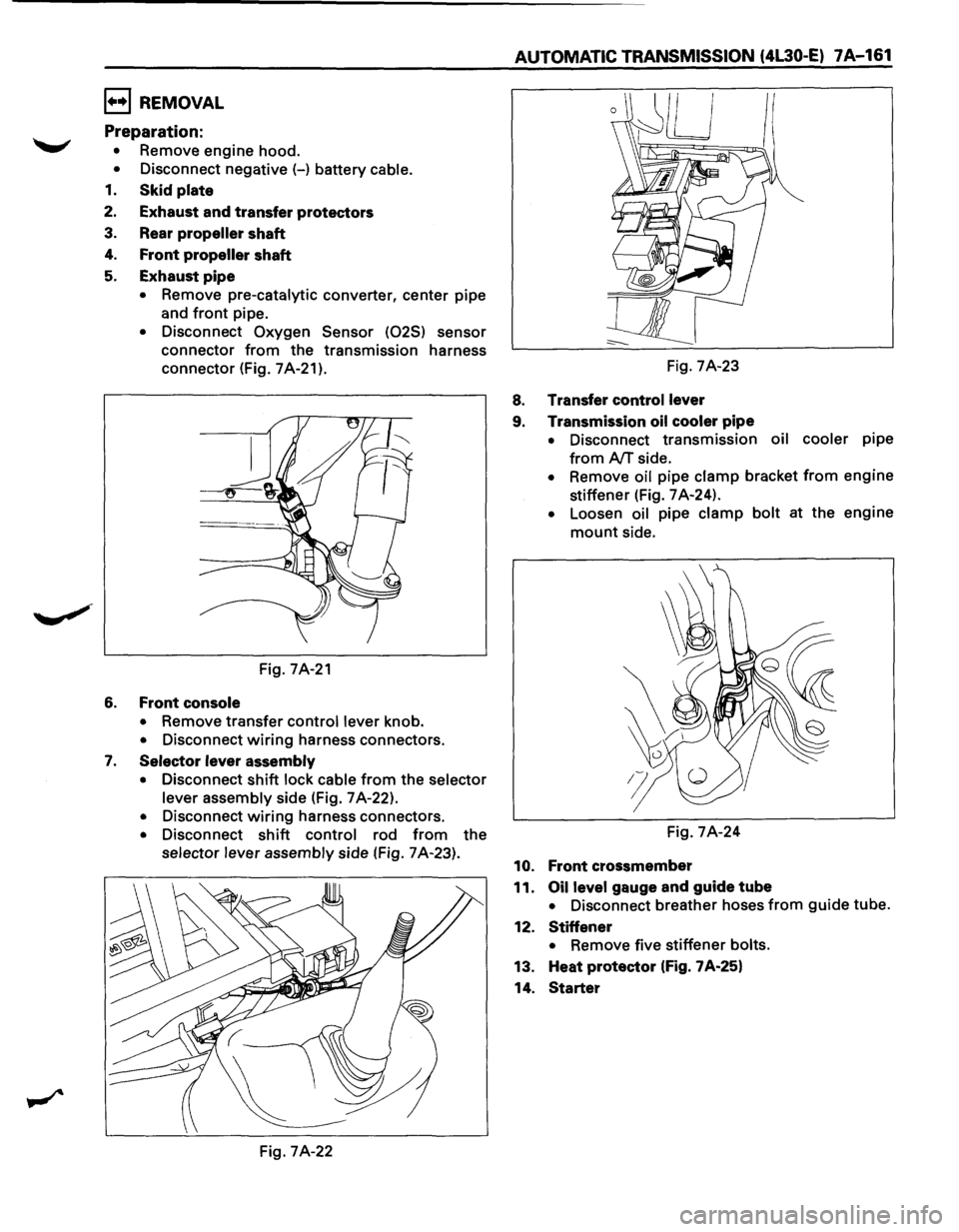
5. Exhaust pipe
• Remove pre-catalytic converter, center pipe
and
front pipe.
• Disconnect Oxygen Sensor (025) sensor
connector
from the transmission harness
connector (Fig.
7A-21).
Fig. 7A-21
6. Front console
• Remove transfer control lever knob.
• Disconnect wiring harness connectors.
7. Selector lever assembly
• Disconnect shift lock cable from the selector
lever assembly
side (Fig. 7 A-22).
• Disconnect wiring harness connectors.
• Disconnect shift control rod from the
selector lever assembly side (Fig. 7 A-23).
Fig. 7A-22
AUTOMATIC TRANSMISSION (4L30·E) 7A-161
Fig. 7A-23
8. Transfer control lever
9. Transmission oil cooler
pipe
• Disconnect transmission oil cooler pipe
from AfT side.
• Remove oil pipe clamp bracket from engine
stiffener (Fig.
7 A-24).
• Loosen oil pipe clamp bolt at the engine
mount side.
Fig.
7A-24
10. Front crossmember
11.
Oil level gauge and guide tube
• Disconnect breather hoses from guide tube.
12.
Stiffener
• Remove five stiffener bolts.
13. Heat protector (Fig. 7A-25}
14.
Starter
Page 1036 of 1928
7A-164 AUTOMATIC TRANSMISSION (4L30-E)
20. Third crossmember
~~~ Torque N·m(lb.ft) 50 (37)
19. Rear mount nut
~~~ Torque N·mOb·ft) 41 (30)
18. Flywheel-torque converter bolt
• Align
the flywheel-torque converter bolt boss
with the starter portion of the converter
housing
by turning torque converter.
• Install flywheel-torque converter bolts (3
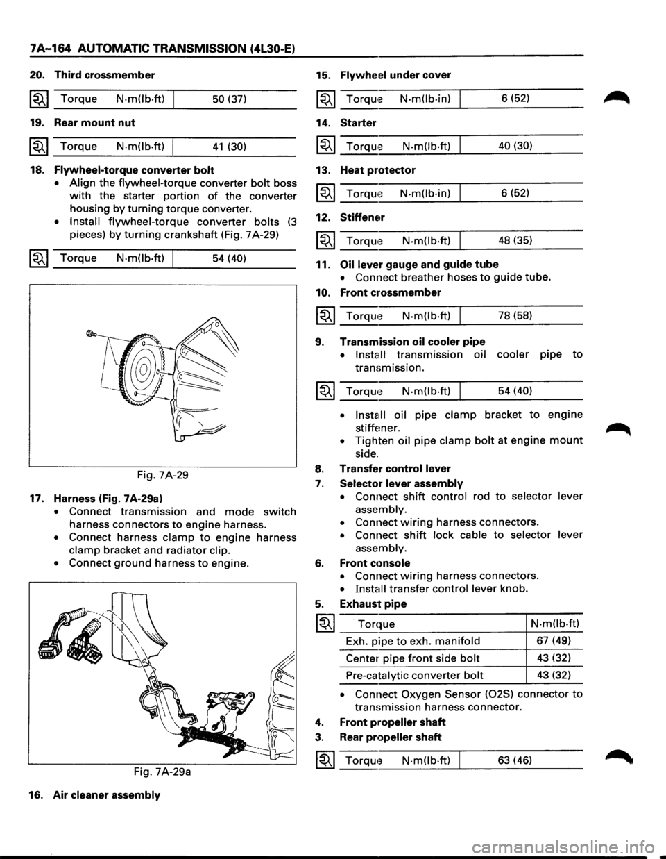
pieces) by turning crankshaft (Fig. 7 A-29)
~~~ Torque N·mOb·ft) 54 (40)
Fig. 7A-29
17. Harness (fig. 7A-29a)
• Connect transmission and mode switch
harness connectors to engine harness.
• Connect harness clamp to engine harness
clamp bracket and radiator clip.
•
Connect ground harness to engine.
Fig. 7A-29a
16. Air
cleaner assembly
15. Flywheel under cover
~~~ TorqUte N·mOb·in)
14. Starter
~~~ Torqu,e N·m(lb·ft)
13. Heat protector
~~~ Torqu'e N·m(lb·in)
12. Stiffener
N·m(lb·ft)
11. Oil lever gauge and guide tube 6
(52)
40 (30)
6 (52)
48 (35)
• Connect breather hoses to guide tube.
10. Front crossmember
~~~ Torque N·m(lb·ft) I 78 (58)
9. Transmission oil cooler pipe
• Install transmission oil cooler pipe to
transmission.
~~~ Torqwe N·m(lb·ft) I 54 (40)
•
lnsta1ll oil pipe clamp bracket to engine
stiffener. .~
• Tighten oil pipe clamp bolt at engine mount
side.
8. Transfer control lever
7. Selector lever assembly
•
Connect shift control rod to selector lever
assembly.
•
Connect wiring harness connectors.
• Connect shift lock cable to selector lever
assembly.
6. Front cc>nsole
• Connect wiring harness connectors.
• Install transfer control lever knob.
5. Exhaust pipe
I~I ___ T_o_r_q~_ue __________________ 4-N_·_m_(l_b_·ft __ )
Exh. pipe
to exh. manifold 67 (49)
Center pipe
front side bolt 43 (32)
Pre-catalytic converter bolt 43 (32)
• Connect Oxygen Sensor (025) connector to
transmission harness connector.
4. Front propeller shaft
3. Rear propeller shaft
~~~ Torqwe N·mOb·ft) 63 (46)
Page 1161 of 1928
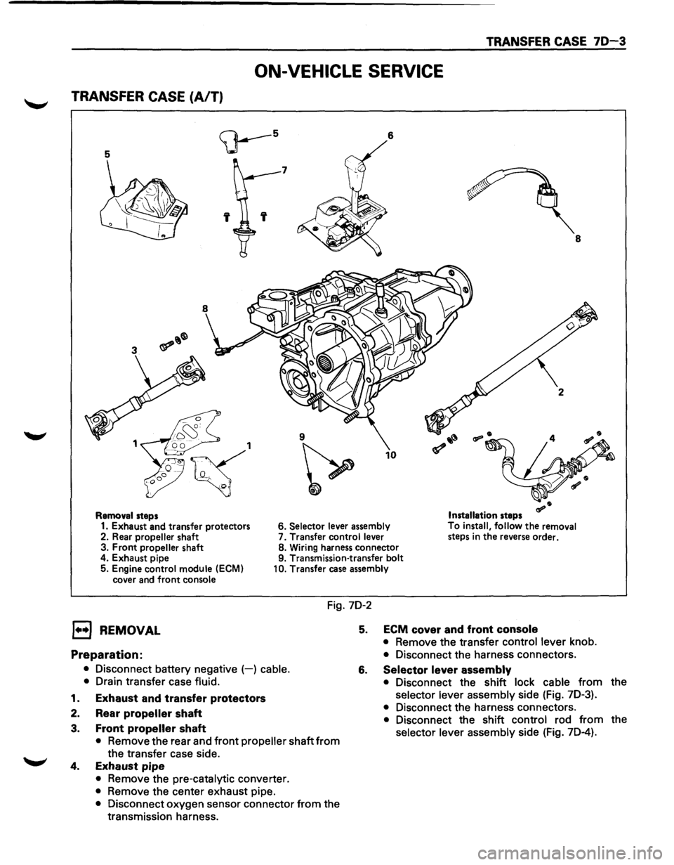
TRANSFER CASE 70-3
ON-VEHICLE SERVICE
TRANSFER CASE (A/T)
5
<;J---5 6
7
' 8
9
~
10
Removal steps Installation steps
1. Exhaust and transfer protectors 6. Selector lever
assembly To
install, follow the removal
steps in the reverse order.
2. Rear propeller shaft 7.
Transfer control lever
3. Front propeller shaft 8.
Wiring harness connector
4. Exhaust pipe 9. Transmission-transfer bolt
5. Engine control module
(ECM)
cover and front console 10.
Transfer case assembly
Fig. 7D-2
l••l REMOVAL
Preparation:
• Disconnect battery negative (-) cable.
•
Drain transfer case fluid.
1. Exhaust and transfer protectors
2. Rear propeller shaft
3. Front propeller shaft
• Remove the rear and front propeller shaft from
the transfer case side.
4. Exhaust pipe
• Remove the pre-catalytic converter.
• Remove the center exhaust pipe.
• Disconnect oxygen sensor connector from the
transmission harness.
5. ECM cover and front console
• Remove the transfer control lever knob.
• Disconnect the harness connectors.
6. Selector lever assembly
• Disconnect the shift lock cable from the
selector lever assembly side (Fig. 7D-3).
• Disconnect the harness connectors.
• Disconnect the shift control rod from the
selector lever assembly side (Fig. 7D-4).
Page 1162 of 1928
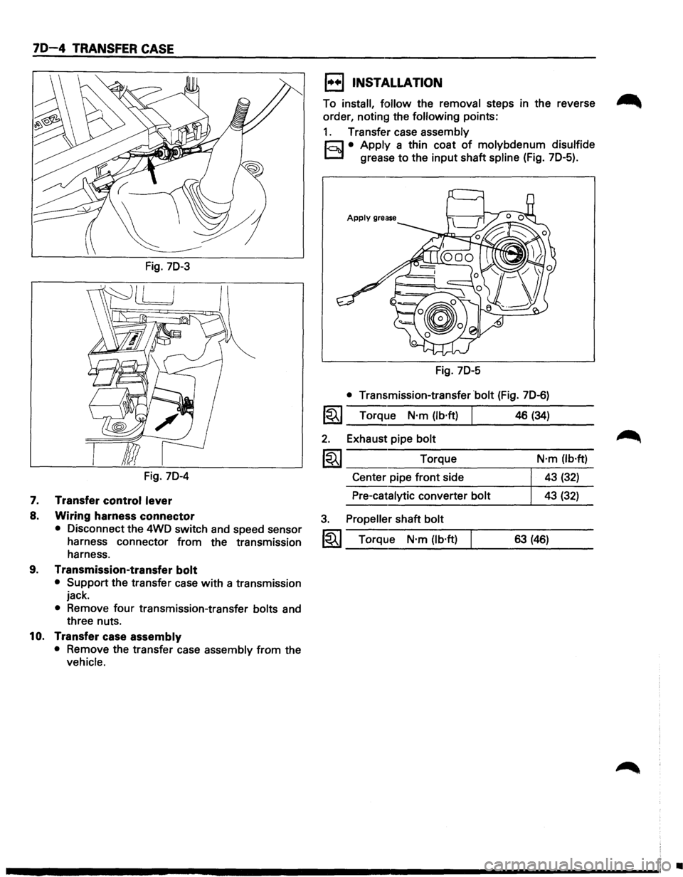
70-4 TRANSFER CASE
Fig. 70-3
Fig. 70-4
7. Transfer control lever
8. Wiring harness connector
• Disconnect the 4WD switch and speed sensor
harness connector from the transmission
harness.
9. Transmission-transfer bolt
• Support the transfer case with a transmission
jack.
• Remove four transmission-transfer bolts and
three nuts.
10. Transfer case assembly
• Remove the transfer case assembly from the
vehicle.
1••1 INSTALLATION
To install, follow the removal steps in the reverse ~
order, noting the following points:
1. Transfer case assembly
r;:;J • Apply a thin coat of molybdenum disulfide
D grease to the input shaft spline (Fig. 70-5).
Fig. 70-5
• Transmission-transfer bolt (Fig. 70-6)
1~1 Torque N·m (lb·ft)
2. Exhaust pipe bolt
1~1 Torque
Center pipe front side
Pre-catalytic converter bolt
3. Propeller shaft bolt
1~1 Torque N·m (lb·ft)
46 (34)
N·m (lb·ft)
43 (32)
43 (32)
63 (46)
•