engine coolant ISUZU TROOPER 1995 User Guide
[x] Cancel search | Manufacturer: ISUZU, Model Year: 1995, Model line: TROOPER, Model: ISUZU TROOPER 1995Pages: 1928
Page 44 of 1928
1A-14 HEATING AND VENTILATION
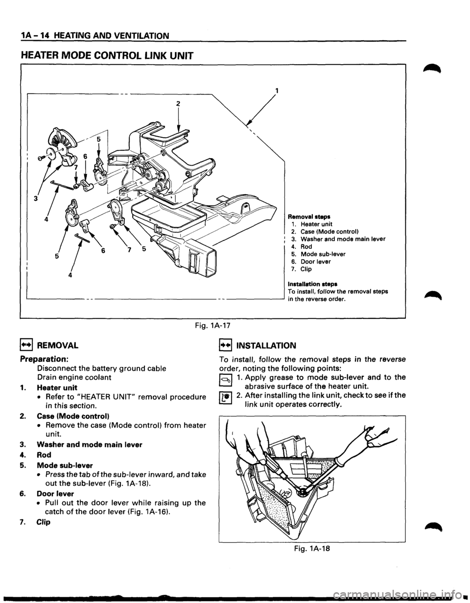
HEATER MODE CONTROL LINK UNIT
2 1
Removal
steps 1. Heater unit 2. Case (Mode control)
3. Washer and mode main lever
4. Rod 5. Mode sub-lever 6. Door lever 7. Clip
Installation
steps
To install, follow the removal steps --------' in the reverse order.
Fig. 1A-17
1••1 REMOVAL
Preparation:
Disconnect the battery ground cable
Drain engine coolant
1. Heater unit
• Refer to "HEATER UNIT" removal procedure
in
this section.
2. Case (Mode control)
•
Remove the case (Mode control) from heater
unit.
3. Washer and mode main lever
4. Rod
5. Mode sub-lever
•
Press the tab of the sub-lever inward, and take
out the sub-lever (Fig. 1A-18).
6. Door lever
• Pull
out the door lever while raising up the
catch
of the door lever (Fig. 1A-16).
7. Clip
I••! INSTALLATION
To install, follow the removal steps in the reverse
order, noting the following points:
1~1 1. Apply grease to mode sub-lever and to the
abrasive surface
of the heater unit.
IL•I 2. After installing the link unit, check to see ifthe
link unit operates correctly.
Fig. 1A-18
•
Page 45 of 1928
HEATING AND VENTILATION 1A-15
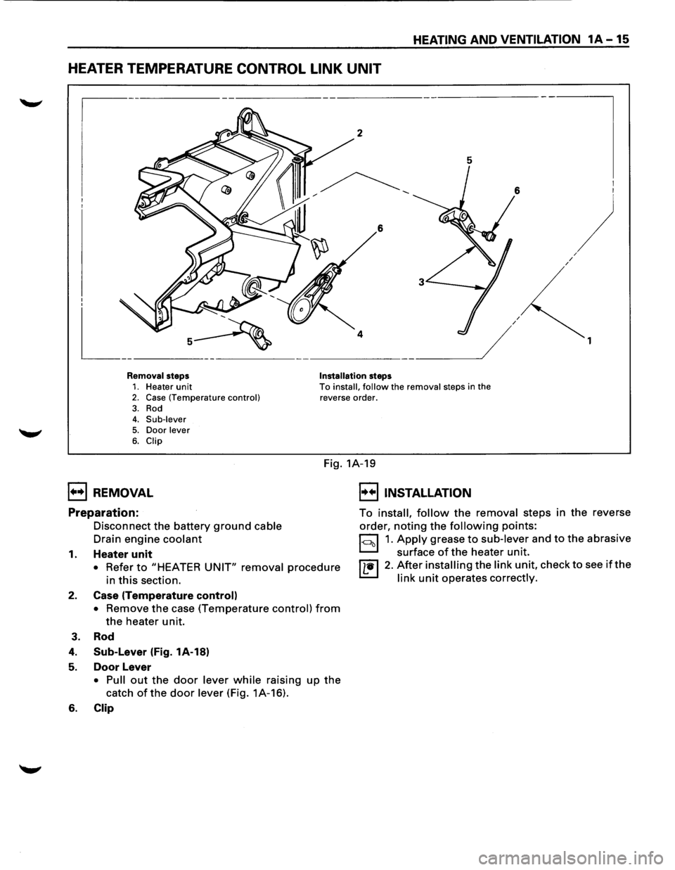
HEATER TEMPERATURE CONTROL LINK UNIT
5
6
/ /
I I
)
1
Removal steps Installation steps 1. Heater unit 2. Case (Temperature control) To install, follow the removal steps in the
reverse order.
3. Rod 4. Sub-lever
5. Door lever 6. Clip
Fig. 1A-19
1••1 REMOVAL
Preparation:
Disconnect the battery ground cable
Drain engine coolant
1. Heater unit
• Refer to "HEATER UNIT" removal procedure
in this section.
2. Case (Temperature control)
• Remove the case (Temperature control) from
the heater unit.
3. Rod
4. Sub-Lever (Fig. 1A-18)
5. Door Lever
• Pull out the door lever while raising up the
catch of the door lever (Fig. 1A-16).
6. Clip
I••! INSTALLATION
To install, follow the removal steps in the reverse
order,
noting the following points:
1~1 1. Apply grease to sub-lever and to the abrasive
surface
of the heater unit.
I L•l 2. After installing the link unit, check to see if the
link unit operates correctly.
Page 68 of 1928
18-14 AIR CONDITIONING
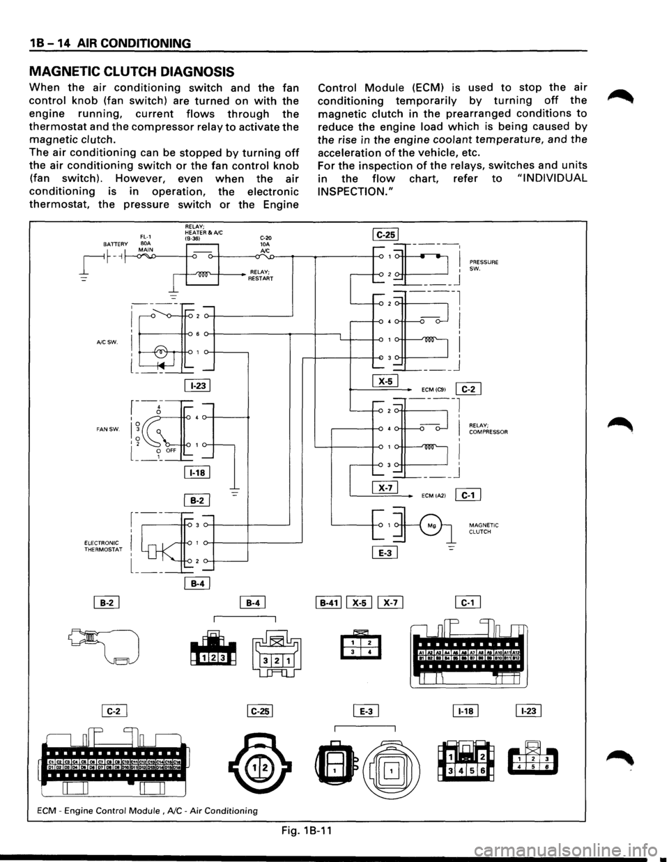
MAGNETIC CLUTCH DIAGNOSIS
When the air conditioning switch and the fan
control knob (fan switch) are turned on with the
engine running, current flows through the
thermostat and the compressor relay to activate the
magnetic clutch.
The air conditioning can be stopped by turning off
the air conditioning switch or the fan control knob
(fan switch). However, even when the air
conditioning is in operation, the electronic
thermostat, the pressure switch or the Engine
BATTER y
~
A/C SW.
FAN SW.
FL-1 BOA MAIN -.Y""'
I
RELAY; HEATER&A/C (8-36)
-
·~
~-----;::: -
I ,--<> -v--ro 2
I 6
! -&r ro 1 l ~ .... --~-'---
11-231
r-g-I 4
I~ 0 I 2 1
l __ 9_ OFF -
lli!J
~
r-----3 I
I 1
I 2 -
ELECTRONIC ~ THERMOSTAT
l __ _
C-20 10A Jd.C
RELAY; RESTART
-=-
ECM -Engine Control Module , NC -Air Conditioning
Control Module (ECM) is used to stop the air
conditioning temporarily by turning off the
magnetic clutch in the prearranged conditions to
reduce the engine load which is being caused by
the rise in the engine coolant temperature, and the
acceleration of the vehicle, etc.
For
the inspection of the relays, switches and units
in the flow chart, refer to "INDIVIDUAL
INSPECTION."
,....-1
2 ......_
.....-=.-2
40. r-
1v-
3
......._ =--
~
I ___ j
PRESSURE
SW.
ECMIC91
~
---2 ----l
•o--
1v-
3
-~-@]
~1
L
[ill
I
I RELAY; COMPRESSOR
I
I I ___ j
ECMIA21 ~
:=:>
MAGNETIC
CLUTCH
,.----I In_ r-r
A1 Kl ., .. ...... A& .. A7 AI ld A10 A11A12 .... •• ., .. a1o an 112
'It!
~
~
Fig.1B-11
Page 499 of 1928
ENGINE DIAGNOSIS S-1
ENGINE
CONTENTS
Engine General Information . . . . . . . . . . . . . . . . . . . . . . . . . . . . . . . . . . . . . . . . . . . . . . . . . . . . . Section S
General
Engine Mechanical .................................................... Section SA
3.2L VS Engine ............................................................... Section SA1
Engine Cooling . . . . . . . . . . . . . . . . . . . . . . . . . . . . . . . . . . . . . . . . . . . . . . . . . . . . . . . . . . . . . . . . Section S8
Engine Fuel . . . . . . . . . . . . . . . . . . . . . . . . . . . . . . . . . . . . . . . . . . . . . . . . . . . . . . . . . . . . . . . . . . . Section SC
Engine Electrical . . . . . . . . . . . . . . . . . . . . . . . . . . . . . . . . . . . . . . . . . . . . . . . . . . . . . . . . . . . . . . Section SD
Driveability and Emissions . . . . . . . . . . . . . . . . . . . . . . . . . . . . . . . . . . . . . . . . . . . . . . . . . . . . Section SE2
Engine Exhaust . . . . . . . . . . . . . . . . . . . . . . . . . . . . . . . . . . . . . . . . . . . . . . . . . . . . . . . . . . . . . . . Section SF
SECTION 6
ENGINE GENERAL INFORMATION
CONTENTS
Description of Engine Section . . . . . . . . . . . . . . . . . . . . . . . . . . . . . . . . . . . . . . . . . . . . . . . . . . . . . . . . S-1
General Description . . . . . . . . . . . . . . . . . . . . . . . . . . . . . . . . . . . . . . . . . . . . . . . . . . . . . . . . . . . . . . . . . S-2
Engine Diagnosis . . . . . . . . . . . . . . . . . . . . . . . . . . . . . . . . . . . . . . . . . . . . . . . . . . . . . . . . . . . . . . . . . . . . S-2
DESCRIPTION OF ENGINE SECTION
SECTIONS-ENGINE GENERAL INFORMATION SECTION S8-ENGINE COOLING
General description
Engine cleanliness and care, and general information
on engine service are covered in this section.
Engine diagnosis
This section covers the components of the fuel,
ignition, and mechanical systems that could cause a
particular complaint, and then outlines repairs in a
logical sequence.
SECTION SA-ENGINE MECHANICAL
This section contains information on the mechanical
parts of the engine, such as cylinder block, cylinder
head, crankshaft, pistons, valve train, camshaft, and
engine
lubrication.
Overhaul
procedures, removal and replacement
procedures, and specifications are also covered.
Specific subsections are:
SA-GENERAL;
Disassembly and reassembly procedures,
inspection and repair procedures
off the vehicle.
6A 1-3.2L V6 ENGINE;
Removal
and replacement procedures on the
vehicle.
Engine cooling system components such as radiator,
engine
coolant pump, thermostat, and cooling fan, are
covered
in this section.
SECTION SC-ENGINE FUEL
This section contains information on all the parts of the
fuel system except the fuel injectors, or throttle body II
unit itself. Items covered are: fuel tank, fuel pump, fuel
filter,
and fuel lines. Specific sections are used for each
fuel system type:
Port
Injection fuel rail and injectors will be found in
Section
6E2.
SECTION SD-ENGINE ELECTRICAL
Items covered in this section are battery, generator,
starter, ignition
coil, spark plugs and wires.
Ignition system diagnosis will be found in Section 6E2
as a "C4" chart.
Specific sections are:
601 -Battery
602 - Cranking System
603 -Charging System
604 -Ignition System
Page 503 of 1928
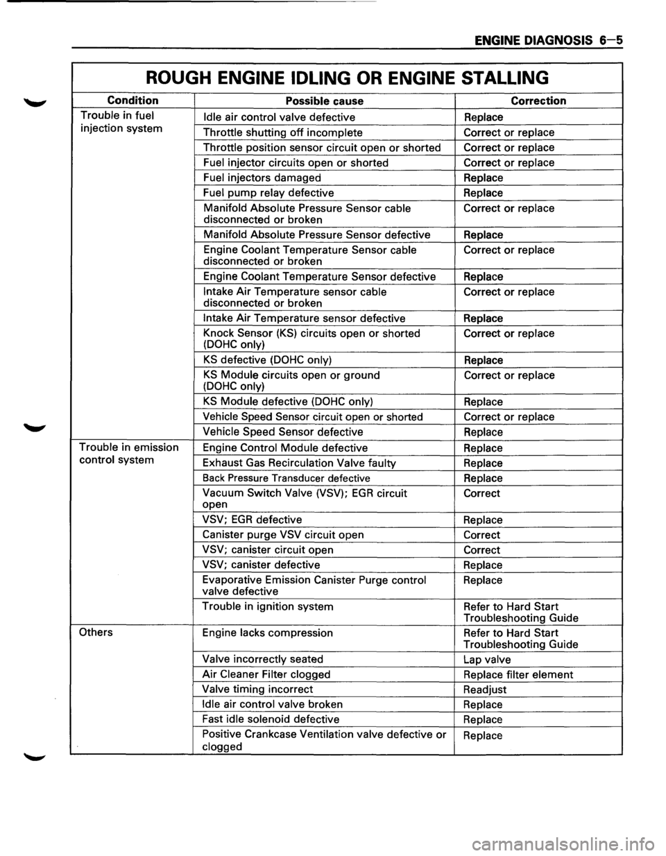
ENGINE DIAGNOSIS 6-5
ROUGH ENGINE IDLING OR ENGINE STALLING
Condition Possible cause Correction
Trouble in fuel
Idle air control valve defective Replace
injection system
Throttle shutting
off incomplete Correct or replace
Throttle position sensor circuit open
or shorted Correct or replace
Fuel injector circuits open or shorted Correct or replace
Fuel injectors damaged
Replace
Fuel pump relay defective Replace
Manifold Absolute Pressure Sensor
cable Correct or replace
disconnected
or broken
Manifold Absolute Pressure Sensor defective
Replace
Engine Coolant Temperature Sensor cable Correct
or replace
disconnected
or broken
Engine Coolant Temperature Sensor defective
Replace
Intake Air Temperature sensor cable Correct or replace
disconnected
or broken
Intake Air Temperature sensor defective
Replace
Knock Sensor
(KS) circuits open or shorted
Correct or replace
(DOHC only)
KS defective (DOHC only) Replace
KS Module circuits open or ground
Correct or replace
(DOHC only)
KS Module defective (DOHC only) Replace
Vehicle Speed Sensor circuit open or shorted
Correct or replace
Vehicle Speed Sensor defective
Replace
Trouble in emission
Engine Control Module defective
Replace
control system
Exhaust Gas Recirculation
Valve faulty
Replace
Back Pressure Transducer defective
Replace
Vacuum Switch Valve (VSV); EGR circuit
Correct
open
VSV; EGR defective Replace
Canister purge
VSV circuit open
Correct
VSV; canister circuit open
Correct
VSV; canister defective
Replace
Evaporative Emission Canister Purge control
Replace
valve defective
Trouble in ignition system
Refer
to Hard Start
Troubleshooting Guide
Others Engine lacks compression
Refer to Hard Start
Troubleshooting Guide
Valve incorrectly seated
Lap valve
Air Cleaner Filter clogged
Replace filter element
Valve timing incorrect
Readjust
Idle air control valve broken
Replace
Fast
idle solenoid defective
Replace
Positive Crankcase Ventilation valve defective
or Replace
clogged
Page 504 of 1928
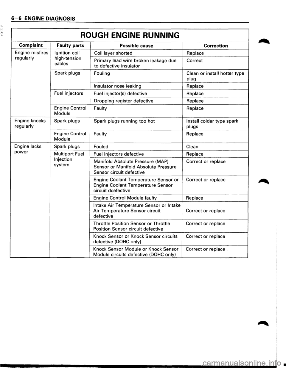
6-6 ENGINE DIAGNOSIS
ROUGH ENGINE RUNNING
Complaint
Faulty parts Possible cause Correction
Engine misfires Ignition coil
Coil layer shorted Replace
regularly
high-tension Primary lead wire broken leakage due
Correct cables to defective insulator
Spark plugs
Fouling Clean
or install hotter type
plug
Insulator
nose leaking Replace
Fuel
injectors Fuel injector(s) defective Replace
Dropping register defective Replace
Engine Control
Faulty Replace
Module
Engine knocks Spark plugs
Spark plugs running too hot Install colder type spark
regularly
plugs
Engine Control Faulty
Replace
Module
Engine lacks Spark plugs
Fouled Clean
power Multipart Fuel
Fuel injectors defective Replace
Injection Manifold Absolute Pressure (MAP)
Correct or replace system Sensor or Manifold Absolute Pressure
Sensor
circuit defective
Engine
Coolant Temperature Sensor or Correct or replace
Engine Coolant Temperature Sensor
circuit dcefective
Engine
Control Module faulty Replace
Intake
Air Temperature Sensor or Intake
Air Temperature Sensor circuit Correct or replace
defective
Throttle Position Sensor or Throttle Correct or replace
Position Sensor
circuit defective
Knock
Sensor or Knock Sensor circuits Correct or replace
defective (DOHC only)
Knock Sensor Module or Knock Sensor Correct or replace .
Module
circuits defective (DOHC only)
•
Page 505 of 1928
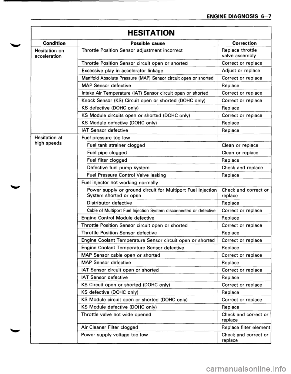
ENGINE DIAGNOSIS 6-7
HESITATION
Condition Possible cause Correction
Hesitation on Throttle
Position Sensor adjustment incorrect Replace
throttle
acceleration valve
assembly
Throttle Position Sensor circuit open
or shorted Correct
or replace
Excessive play in accelerator linkage
Adjust or replace
Manifold Absolute
Pressure (MAP) Sensor circuit open or shorted Correct or replace
MAP Sensor defective Replace
Intake Air
Temperature (IAT) Sensor circuit open or shorted Correct or replace
Knock Sensor
(KS) Circuit open or shorted (DOHC only) Correct or replace
KS defective (DOHC only) Replace
KS Module circuits open or shorted (DOHC only) Correct or replace
KS Module defective (DOHC only) Replace
IAT Sensor defective Replace
Hesitation at
Fuel pressure
too low
high speeds
Fuel tank strainer clogged Clean or replace
Fuel pipe clogged
Clean or replace
Fuel filter clogged
Replace
Defective fuel
pump system Check and replace
Fuel Pressure Control Valve leaking Replace
Fuel injector
not working normally
Power supply or ground circuit for Multipart Fuel Injection Check and correct or
System shorted or open
replace
Distributor defective Replace
Cable of Multipart Fuel Injection System disconnected or defective Correct or replace
Engine Control Module defective Replace
Throttle Position Sensor circuit open
or shorted Correct or replace
Throttle Position Sensor defective Replace
Engine Coolant Temperature Sensor circuit open
or shorted Correct or replace
Engine Coolant Temperature Sensor defective Replace
MAP Sensor cable open
or shorted Correct or replace
MAP Sensor defective
Replace
IAT Sensor circuit open or shorted
Correct or replace
IAT Sensor defective Replace
KS Circuit open or shorted (DOHC only)
Correct or replace
KS defective (DOHC only) Replace
KS Module circuit open or shorted (DOHC only) Correct or replace
KS Module defective (DOHC only) Replace
Throttle valve
not wide opened
Check and correct or
replace
Air Cleaner Filter clogged
Replace filter element
Power supply voltage
too low Check and correct or
replace
Page 506 of 1928
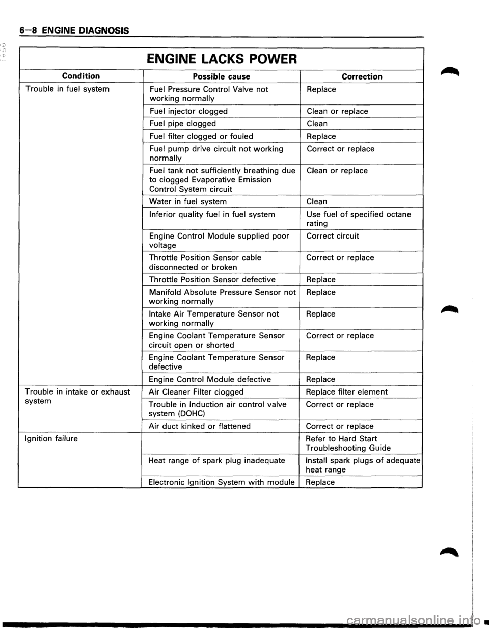
6-8 ENGINE DIAGNOSIS
ENGINE LACKS POWER
Condition
Possible cause Correction
Trouble in fuel system Fuel Pressure Control Valve not Replace
working normally
Fuel
injector clogged Clean or replace
Fuel
pipe clogged Clean
Fuel filter clogged
or fouled Replace
Fuel
pump drive circuit not working Correct or replace
normally
Fuel tank not sufficiently breathing due Clean or replace
to clogged Evaporative Emission
Control System circuit
Water in
fuel system Clean
Inferior quality fuel
in fuel system Use fuel of specified octane
rating
Engine
Control Module supplied poor Correct circuit
voltage
Throttle
Position Sensor cable Correct or replace
disconnected or broken
Throttle Position Sensor defective Replace
Manifold Absolute
Pressure Sensor not Replace
working normally
Intake Air Temperature Sensor not Replace
working normally
Engine Coolant Temperature Sensor Correct or replace
circuit open or shorted
Engine
Coolant Temperature Sensor Replace
defective
Engine
Control Module defective Replace
Trouble
in intake or exhaust Air Cleaner Filter clogged Replace filter element
system Trouble in Induction air control valve Correct or replace
system (DOHC)
Air duct kinked or flattened Correct or replace
Ignition failure
Refer to Hard Start
Troubleshooting Guide
Heat range
of spark plug inadequate Install spark plugs of adequate
heat range
Electronic Ignition System with module Replace
•
Page 507 of 1928
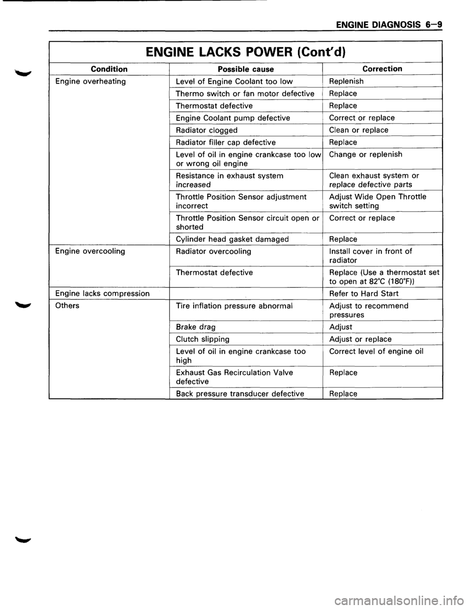
ENGINE DIAGNOSIS 6-9
ENGINE LACKS POWER (Cont'd)
Condition Possible cause Correction
Engine overheating
Level of Engine Coolant too low Replenish
Thermo switch or fan motor defective Replace
Thermostat defective Replace
Engine
Coolant pump defective Correct or replace
Radiator clogged
Clean or replace
Radiator
filler cap defective Replace
Level
of oil in engine crankcase too low Change or replenish
or
wrong oil engine
Resistance in exhaust system
Clean exhaust system or
increased replace
defective parts
Throttle Position Sensor adjustment Adjust
Wide Open Throttle
incorrect switch setting
Throttle Position Sensor circuit open
or Correct or replace
shorted
Cylinder head gasket damaged Replace
Engine overcooling
Radiator
overcooling Install cover
in front of
radiator
Thermostat defective Replace
(Use a thermostat set
to open at a2·c (180.F))
Engine
lacks compression Refer to Hard Start
Others Tire inflation pressure
abnormal Adjust to recommend
pressures
Brake drag Adjust
Clutch slipping Adjust or replace
Level
of oil in engine crankcase too Correct level of engine oil
high
Exhaust Gas
Recirculation Valve Replace
defective
Back pressure transducer defective
Replace
Page 510 of 1928
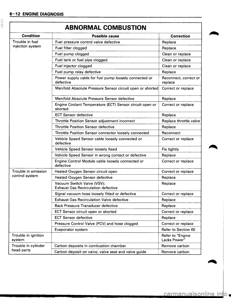
6-12 ENGINE DIAGNOSIS
ABNORMAL COMBUSTION
Condition
Possible cause Correction
Trouble in fuel Fuel pressure control valve defective Replace
injection system
Fuel filter clogged
Replace
Fuel pump clogged Clean or replace
Fuel tank
or fuel pipe clogged Clean or replace
Fuel injector clogged Clean or replace
Fuel
pump relay defective
Replace
Power supply cable for fuel pump loosely connected or Reconnect, correct or
defective
replace
Manifold Absolute
Pressure Sensor circuit open or shorted Correct or replace
Manifold Absolute
Pressure Sensor defective Replace
Engine Coolant Temperature
(ECT) Sensor circuit open or Correct or replace
shorted
ECT Sensor defective
Replace
Throttle
Position Sensor adjustment incorrect Replace throttle valve
Throttle
Position Sensor defective
Replace
Throttle
Position Sensor connector loosely connected Reconnect
Vehicle Speed Sensor cable loosely connected or Correct or replace
defective
Vehicle Speed Sensor loosely fixed Fix tightly
Vehicle Speed Sensor in wrong contact or defective Replace
Engine Control Module cable
loosely connected or Correct or replace
defective
Trouble in emission
Heated
Oxygen Sensor circuit open Correct or replace
control system
Heated
Oxygen Sensor defective Replace
Vacuum Switch
Valve (VSV); Replace
Exhaust Gas Recirculation defective
Signal vacuum hose loosely fitted or defective Correct or replace
Exhaust Gas Recirculation
Valve defective Replace
Back
Pressure Transducer defective Replace
ECT Sensor circuit open or shorted Correct or replace
ECT Sensor defective Replace
Pressure Control Valve (PCV) and hose clogged Correct or replace
Evaporator system
Refer
to Section 6E
Trouble in ignition
Refer to "Engine
system Lacks
Power"
Trouble in cylinder
Carbon deposits in combustion chamber Remove carbon
head parts
Carbon deposit on valve,
valve seat and valve guide
Remove carbon
•