engine coolant ISUZU TROOPER 1995 Owner's Manual
[x] Cancel search | Manufacturer: ISUZU, Model Year: 1995, Model line: TROOPER, Model: ISUZU TROOPER 1995Pages: 1928
Page 513 of 1928
ENGINE DIAGNOSIS 6-15
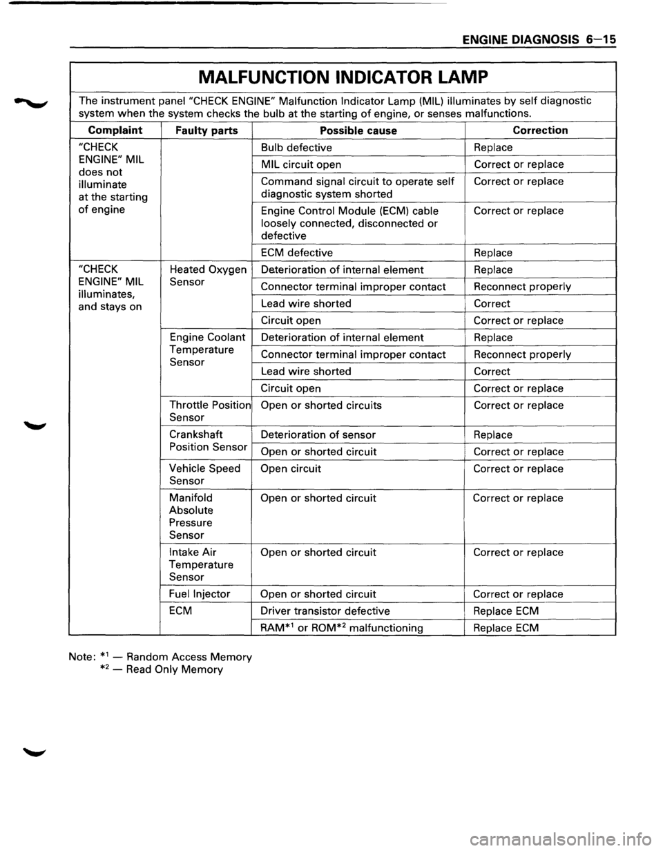
MALFUNCTION INDICATOR LAMP
The instrument panei"CHECK ENGINE" Malfunction Indicator Lamp (MIL) illuminates by self diagnostic
system
when the system checks the bulb at the starting of engine, or senses malfunctions.
Complaint
Faulty parts
"CHECK
ENGINE" MIL
does not
illuminate
at the starting
of engine
"CHECK Heated Oxygen
ENGINE" MIL Sensor
illuminates,
and stays on
Engine
Coolant
Temperature Sensor
Throttle Position
Sensor
Crankshaft Position Sensor
Vehicle Speed
Sensor
Manifold
Absolute
Pressure Sensor
Intake Air
Temperature Sensor
Fuel Injector
ECM
Note: *1
-Random Access Memory
*2
-Read Only Memory
Possible cause Correction
Bulb defective Replace
MIL
circuit open Correct or replace
Command signal
circuit to operate self Correct or replace
diagnostic system shorted
Engine
Control Module (ECM) cable Correct or replace
loosely
connected, disconnected or
defective
ECM defective Replace
Deterioration of internal element Replace
Connector terminal improper contact Reconnect properly
Lead wire shorted Correct
Circuit
open Correct or replace
Deterioration of internal element Replace
Connector terminal improper contact Reconnect properly
Lead wire shorted Correct
Circuit
open Correct or replace
Open
or shorted circuits Correct or replace
Deterioration of sensor Replace
Open
or shorted circuit Correct or replace
Open
circuit Correct or replace
Open
or shorted circuit Correct or replace
Open
or shorted circuit Correct or replace
Open
or shorted circuit Correct or replace
Driver transistor defective Replace ECM
RAM*1 or ROM*2 malfunctioning Replace ECM
Page 561 of 1928
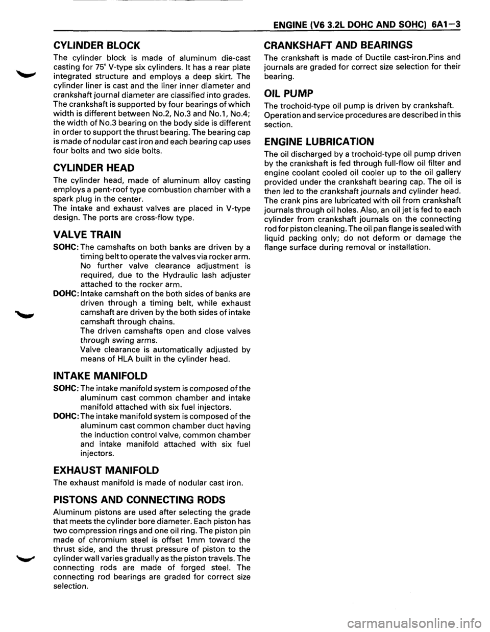
CYLINDER BLOCK
The cylinder block is made of aluminum die-cast
casting
for 75° V-type six cylinders. It has a rear plate
integrated structure and employs a deep skirt. The
cylinder liner is cast and the liner inner diameter and
crankshaft
journal diameter are classified into grades.
The crankshaft is supported by four bearings
of which
width is different between No.2, No.3 and No.1, No.4;
the
width of No.3 bearing on the body side is different
in order
to support the thrust bearing. The bearing cap
is made
of nodular cast iron and each bearing cap uses
four bolts and two side bolts.
CYLINDER HEAD
The cylinder head, made of aluminum alloy casting
employs a pent-roof type combustion chamber with a
spark
plug in the center.
The intake and exhaust
valves are placed in V-type
design. The ports are cross-flow type.
VALVE TRAIN
SOHC: The camshafts on both banks are driven by a
timing
belt to operate the valves via rocker arm.
No
further valve clearance adjustment is
required, due
to the Hydraulic lash adjuster
attachedtotherockerarm.
DOHC: Intake camshaft on the both sides of banks are
driven through a
timing belt, while exhaust
camshaft are driven by the both sides
of intake
camshaft through chains.
The driven camshafts open and
close valves
through swing arms.
Valve clearance is automatically adjusted by
means
of HLA built in the cylinder head.
INTAKE MANIFOLD
SOHC: The intake manifold system is composed ofthe
aluminum cast common chamber and intake
manifold attached with six fuel injectors.
DOHC: The intake manifold system is composed of the
aluminum cast common chamber duct having
the induction
control valve, common chamber
and intake
manifold attached with six fuel
injectors.
EXHAUST MANIFOLD
The exhaust manifold is made of nodular cast iron.
PISTONS AND CONNECTING RODS
Aluminum pistons are used after selecting the grade
that meets the cylinder bore diameter. Each piston has
two compression rings and one oil ring. The piston pin
made
of chromium steel is offset 1 mm toward the
thrust side, and the thrust pressure
of piston to the
cylinder wall varies gradually as the piston travels. The
connecting rods are made
of forged steel. The
connecting rod bearings are graded
for correct size
selection.
ENGINE (V6 3.2L DOHC AND SOHC) 6A1-3
CRANKSHAFT AND BEARINGS
The crankshaft is made of Ductile cast-iron.Pins and
journals are graded for correct size selection for their
bearing.
OIL PUMP
The trochoid-type oil pump is driven by crankshaft.
Operation and service procedures are described in this
section.
ENGINE LUBRICATION
The oil discharged by a trochoid-type oil pump driven
by the crankshaft is fed through full-flow oil filter and
engine
coolant cooled oil cooler up to the oil gallery
provided under the crankshaft bearing cap. The oil is
then
led to the crankshaft journals and cylinder head.
The crank pins are
lubricated with oil from crankshaft
journals through oil holes. Also, an oil jet is fed to each
cylinder from crankshaft journals on the connecting
rod
for piston cleaning. The oil pan flange is sealed with
liquid packing only; do not deform or damage the
flange surface during removal or installation.
Page 601 of 1928
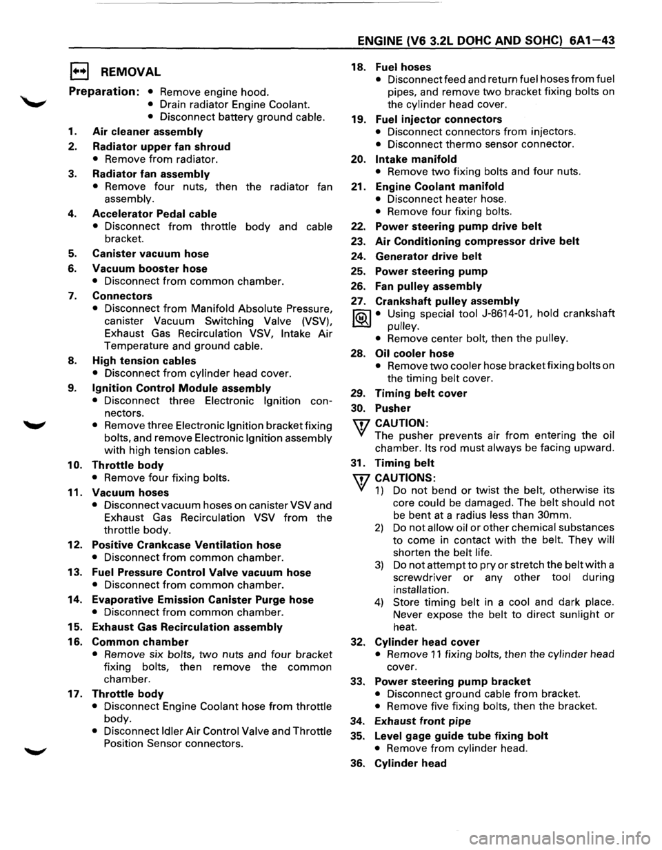
EJ REMOVAL
Preparation: • Remove engine hood.
• Drain radiator Engine Coolant.
• Disconnect battery ground cable.
1. Air cleaner assembly
2. Radiator upper fan shroud
• Remove from radiator.
3. Radiator fan assembly
• Remove four nuts, then the radiator fan
assembly.
4. Accelerator Pedal cable
• Disconnect from throttle body and cable
bracket.
5. Canister vacuum hose
6. Vacuum booster hose
• Disconnect from common chamber.
7. Connectors
• Disconnect from Manifold Absolute Pressure,
canister Vacuum Switching
Valve (VSV),
Exhaust Gas Recirculation VSV,
Intake Air
Temperature and ground cable.
8. High tension cables
• Disconnect from cylinder head cover.
9. Ignition Control Module assembly
• Disconnect three Electronic Ignition con
nectors.
• Remove three Electronic Ignition bracket fixing
bolts, and remove Electronic Ignition assembly
with high tension cables.
10. Throttle body
• Remove four fixing bolts.
11. Vacuum hoses
• Disconnect vacuum hoses on canister VSV and
Exhaust Gas Recirculation VSV
from the
throttle body.
12. Positive Crankcase Ventilation hose
• Disconnect from common chamber.
13. Fuel Pressure Control Valve vacuum hose
• Disconnect from common chamber.
14. Evaporative Emission Canister Purge hose
• Disconnect from common chamber.
15. Exhaust Gas Recirculation assembly
16. Common chamber
• Remove six bolts, two nuts and four bracket
fixing bolts, then remove the
common
chamber.
17. Throttle body
• Disconnect Engine Coolant hose from throttle
body.
• Disconnect Idler Air Control Valve and Throttle
Position Sensor connectors.
ENGINE (V6 3.2L DOHC AND SOHC) 6A1-43
18. Fuelhoses
• Disconnect feed and return fuel hoses from fuel
pipes, and remove two bracket fixing bolts on
the cylinder head cover.
19. Fuel injector connectors
• Disconnect connectors from injectors.
• Disconnect thermo sensor connector.
20. Intake manifold
• Remove two fixing bolts and four nuts.
21. Engine Coolant manifold
• Disconnect heater hose.
• Remove four fixing bolts.
22. Power steering pump drive belt
23. Air Conditioning compressor drive belt
24. Generator drive belt
25. Power steering pump
26.
Fan pulley assembly
27. Crankshaft pulley assembly
~ • Using special tool J-8614-01, hold crankshaft
~ pulley.
•
Remove center bolt, then the pulley.
28. Oil cooler hose
• Remove two cooler hose bracket fixing bolts on
the timing
belt cover.
29. Timing belt cover
30. Pusher
\fl CAUTION:
VI The pusher prevents air from entering the oil
chamber. Its rod must always be facing upward.
31. Timing belt
\fl CAUTIONS:
VI 1) Do not bend or twist the belt, otherwise its
core
could be damaged. The belt should not
be bent at a radius less than 30mm.
2) Do not allow oil or other chemical substances
to come in contact with the belt. They will
shorten the belt life.
3) Do not attempt to pry or stretch the belt with a
screwdriver
or any other tool during
installation.
4) Store timing belt in a cool and dark place.
Never expose the
belt to direct sunlight or
heat.
32. Cylinder head cover
• Remove 11 fixing bolts, then the cylinder head
cover.
33. Power steering pump bracket
• Disconnect ground cable from bracket.
• Remove five fixing bolts, then the bracket.
34. Exhaust front pipe
35.
Level gage guide tube fixing bolt
• Remove from cylinder head.
36. Cylinder head
Page 602 of 1928
'.:.:.
6A1-44 ENGINE (V6 3.2L DOHC AND SOHC)
1••1 INSTALLATION
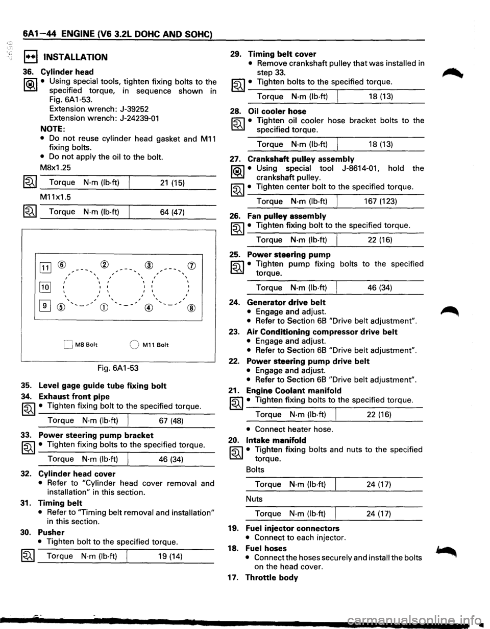
36. Cylinder head
l"i:a\1 • Using special tools, tighten fixing bolts to the
~ specified torque, in sequence shown in
Fig.
6A 1-53.
Extension wrench: J-39252
Extension wrench: J-24239-01
NOTE:
• Do not reuse cylinder head gasket and M11
fixing bolts.
• Do not apply the oil to the bolt.
M8x1.25
1~1 Torque N·m (lb·ft)
M11x1.5
21 (15)
~~~ Torque N·m (lb·ft) 64 (47)
[ill ® ® @ , , , I I I
~
I
I I
I I
I I I
I I
I I I
I I
I
0
' , , ' ' , ' , ' ® '-~ CD @
M8 Bolt QM11Bolt
Fig. 6A1-53
35. Level gage guide tube fixing bolt
34. Exhaust front pipe
' '
, ,
(j)
I
I
I
@
~~~ • Tighten fixing bolt to the specified torque.
Torque
N·m (lb·ft) I 67 (48)
33. Power steering pump bracket
~~~· Tighten fixing bolts to the specified torque.
Torque
N·m (lb·ft) I 46 (34)
32. Cylinder head cover
• Refer to "Cylinder head cover removal and
installation" in this section.
31. Timing belt
• Refer to "Timing belt removal and installation"
in this section.
30. Pusher
• Tighten bolt to the specified torque.
1~1 Torque N·m (lb·ft) I 19 (14)
29. Timing belt cover
• Remove crankshaft pulley that was installed in
step
33.
~~~· Tighten bolts to the specified torque.
Torque
N·m (lb·ft) I 18 (13)
28. Oil cooler hose
~ • Tighten oil cooler hose bracket bolts to the
~ specified torque.
Torque
N·m(lb·ft) I 18(13)
27. Crankshaft pulley assembly
l"i:a\1 • Using special tool J-8614-01, hold the
~ crankshaft pulley.
~~~· Tighten center bolt to the specified torque.
Torque
N·m (lb·ft) I 167 (123)
26. Fan pulley assembly
~~~ • Tighten fixing bolt to the specified torque.
Torque
N·m (lb·ft) I 22 (16)
25. Power steering pump
~ • Tighten pump fixing bolts to the specified
~ torque.
Torque
N-m (lb·ft) 46 (34)
24. Generator drive belt
• Engage and adjust.
• Refer to Section 68 "Drive belt adjustment".
23. Air Conditioning compressor drive belt
• Engage and adjust.
• Refer to Section 68 "Drive belt adjustment".
22. Power steering pump drive belt
• Engage and adjust.
• Refer to Section 68 "Drive belt adjustment".
21. Engine Coolant manifold
~~~· Tighten fixing bolts to the specified torque.
Torque
N·m (lb·ft) J 22 (16)
• Connect heater hose.
20. Intake manifold
~ • Tighten fixing bolts and nuts to the specified
~ torque.
Bolts
Torque N-m (lb·ft) 24 (17)
Nuts
Torque
N-m (lb·ft) 24 (17)
19. Fuel injector connectors
• Connect to each injector.
18. Fuelhoses
• Connect the hoses securely and install the bolts
on the head cover.
17. Throttle body
..
Page 603 of 1928
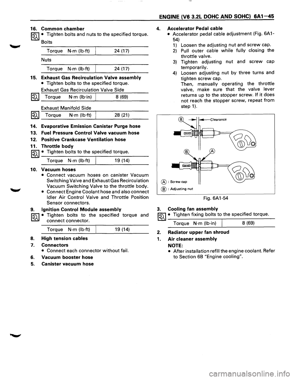
16. Common chamber
~~~· Tighten bolts and nuts to the specified torque.
Bolts
Torque N·m (lb·ft) 24 (17)
Nuts
Torque
N·m (lb·ft) 24 (17)
15. Exhaust Gas Recirculation Valve assembly
• Tighten bolts to the specified torque.
Exhaust Gas
Recirculation Valve Side
~~~ Torque N·m (lb·in) I 8 (69)
Exhaust Manifold Side
~~~ Torque N·m (lb·ft) 28 (21)
14. Evaporative Emission Canister Purge hose
13.
Fuel Pressure Control Valve vacuum hose
12. Positive
Crankcase Ventilation hose
11.
Throttle body
~~~· Tighten bolts to the specified torque.
Torque
N·m (lb·ft) I 19 (14)
10. Vacuum hoses
• Connect vacuum hoses on canister Vacuum
Switching Valve and Exhaust Gas Recirculation
Vacuum
Switching Valve to the throttle body.
• Connect Engine Coolant hose and also connect
Idler Air Control Valve and Throttle Position
Sensor connectors.
9. Ignition Control Module assembly
~ • Tighten bolts to the specified torque
~ connect connector. and
Torque
N·m (lb·ft) 19 (14)
8. High tension cables
7. Connectors
• Connect each connector without fail.
6. Vacuum booster hose
5. Canister vacuum hose
ENGINE (V6 3.2L DOHC AND SOHC) 6A 1-45
4. Accelerator Pedal cable
• Accelerator pedal cable adjustment (Fig. 6A 1-
54)
1) Loosen the adjusting nut and screw cap.
2) Pull outer cable while fully closing the
throttle valve.
3) Tighten adjusting nut and screw cap
temporarily.
4) Loosen adjusting nut by three turns and
tighten
screw cap.
Then,
manually operating the throttle
valve, make sure that the valve lever
returns up to the stopper screw. If it does
not reach the stopper screw, repeat
from
step 1 ).
@:Screw cap
@ : Adjusting nut
Fig. 6A1-54
3. Cooling fan assembly
~~~· Tighten fixing bolts to the specified torque.
Torque
N·m (lb·in) I 8 (69)
2. Radiator upper fan shroud
1. Air cleaner assembly
NOTE:
• After installation refill the engine coolant. Refer
to Section 68 "Engine cooling".
Page 605 of 1928
1••1 REMOVAL
Preparation: • Remove engine hood.
• Drain radiator Engine Coolant.
•
Disconnect battery ground cable.
1.
Air cleaner assembly
2. Radiator upper fan shroud
• Remove from radiator.
3. Radiator fan assembly
• Remove four nuts, then the radiator fan
assembly.
4. Accelerator Pedal cable
• Disconnect from throttle body and cable
bracket.
5. Canister vacuum hose
• Disconnect from vacuum pipe.
6.
Vacuum booster hose
• Disconnect from common chamber.
7. Connectors
• Disconnect from Manifold Absolute Pressure,
canister Vacuum Switching Valve (VSV),
Exhaust
Gas Recirculation VSV, Intake Air
Temperature and ground cable.
8. High tension cables
• Disconnect from cylinder head cover.
9. Ignition Control Module assembly
• Disconnect three Electronic Ignition con
nectors.
• Remove three Electronic Ignition bracket fixing
bolts, and remove Electronic
Ignition assembly
with high tension cables.
10. Throttle body
• Remove four fixing bolts.
11.
Vacuum hoses
• Disconnect vacuum hoses on canister VSV and
Exhaust
Gas Recirculation VSV from the
throttle body.
12.
Positive Crankcase Ventilation hose
• Disconnect from common chamber.
13. Fuel Pressure
Control Valve vacuum hose
• Disconnect from common chamber.
14.
Canister vacuum hose
• Disconnect from common chamber.
15.
Exhaust Gas Recirculation Valve assembly
• Remove five bolts from common chamber,
exhaust manifold and cylinder head cover.
16.
Common chamber duct
• Remove four bolts, four nuts and three bracket
fixing bolts, then remove the
common
chamber.
• Disconnect ground cable from rear side of
common chamber.
ENGINE (V6 3.2L DOHC AND SOHC) 6A1 47
17. Throttle body
• Disconnect Engine Coolant hose from throttle
body.
• Disconnect Idle Air Control Valve and Throttle
Position Sensor connectors.
18.
Common chamber
• Remove six bolts and two nuts.
• Remove fixing bolts on common chamber
bracket, then the
common chamber.
19.
Fuelhoses
• Disconnect feed and return fuel hoses from fuel
pipes, and remove
two bracket fixing bolts on
the cylinder head cover.
20. Fuel injector connectors
• Disconnect connectors from injectors.
• Disconnect thermo sensor connector.
21.
Intake manifold
• Remove two fixing bolts and four nuts.
22. Engine
Coolant manifold
• Disconnect heater hose.
• Remove four fixing bolts.
23.
Power steering pump drive belt
24. Air Conditioning compressor drive belt
25. Generator drive belt
26. Power steering pump
27. Fan pulley assembly
28. Crankshaft pulley assembly
I®J • Using special tool J-8614-01, hold crankshaft
pulley.
•
Remove center bolt, then the pulley.
29. Oil cooler hose
• Remove two cooler hose bracket fixing bolts on
the timing belt cover.
30. Timing belt cover
31. Pusher
CAUTION:
The pusher prevents air from entering the oil
chamber. Its rod must always be facing upward.
32.
Timing belt
w CAUTIONS:
' 1) Do not bend or twist the belt, otherwise its
core could
be damaged. The belt should not
be bent at a radius less than 30mm.
2) Do not allow oil or other chemical substances
to come in contact
with the belt. They will
shorten the belt life.
3) Do not attempt to pry or stretch the belt with a
screwdriver
or any other tool during
installation.
4) Store timing belt in a cool and dark place.
Never expose the belt to direct sunlight
or
heat.
Page 606 of 1928
~:· T·, ·.}:
6A1-48 ENGINE (V6 3.2L DOHC AND SOHC)
33. Cylinder head cover
• Remove 11 fixing bolts, then the cylinder head
cover.
34. Power steering pump bracket
• Disconnect ground cable from bracket.
35.
• Remove five fixing bolts, then the bracket.
Exhaust front pipe
36.
37. Level gage fixing bolt
• Remove from cylinder head.
Cylinder head
1••1 INSTALLATION
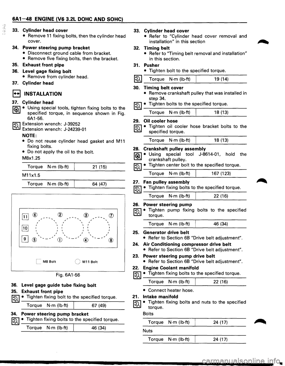
37. Cylinder head
li0\1 • Using special tools, tighten fixing bolts to the
~ specified torque, in sequence shown in Fig.
6A1-56.
~ Extension wrench: J-39252
t:6.l Extension wrench: J-24239-01
NOTE:
• Do not reuse cylinder head gasket and M11
fixing bolts.
•
Do not apply the oil to the bolt.
M8x1.25
Torque
N·m (lb·ft) 21 (15)
M11x1.5
Torque
N·m (lb·ft) 64 (47)
OJ] ® ® ® , ' ' ,
, I , ,
[IQJ ' I I
I I
I I I
I I
I I I
I I
,
[I] ' , , ' @ ' ,
CD ' , , __
@
[[ M8 Bolt (J M11 Bolt
Fig.
6A1-56
36. Level gage guide tube fixing bolt
35. Exhaust front pipe
'
,
(])
I
I
I
,
@
~~~ • Tighten fixing bolt to the specified torque.
Torque
N·m (lb·ft) I 67 (49)
34. Power steering pump bracket
~~~ • Tighten fixing bolts to the specified torque.
Torque
N·m (lb·ft) I 46 (34)
33.
32.
31.
Cylinder head cover
• Refer to "Cylinder head cover removal and
installation" in this section
Timing belt
• Refer to "Timing belt removal and installation"
in this section.
Pusher
• Tighten bolt to the specified torque.
I~I __ T_o_r~qu_e __ N_·_m~(lb_·ft_)~ ______ 1_9_(1_4_) ____ _
30. Timing belt cover
• Remove crankshaft pulley that was installed in
step 34.
~~~· Tighten bolts to the specified torque.
Torque
N·m (lb·ft) I 18 (13)
29. Oil cooler hose
~ • Tighten oil cooler hose bracket bolts to the
t:6.l specified torque.
Torque
N·m (lb·ft) I 18 (13)
28. Crankshaft pulley assembly
li0\1 • Using special tool J-8614-011 hold the
~ crankshaft pulley.
~~~ • Tighten center bolt to the specified torque.
Torque
N·m (lb·ft) I 167 (123)
27. Fan pulley assembly
~~~· Tighten fixing bolts to the specified torque.
Torque
N·m (lb·ft) I 22 (16)
26. Power steering pump
~ • Tighten pump fixing bolts to the specified
t:6.l torque.
Torque
N·m (lb·ft) I 46 (34)
25. Generator drive belt
• Refer to Section 68 "Drive belt adjustment".
24.
Air Conditioning compressor drive belt
• Refer to Section 68 "Drive belt adjustment".
23. Power steering pump drive belt
• Refer to Section 68 "Drive belt adjustment".
22. Engine Coolant manifold
~~~· Tighten fixing bolts to the specified torque.
Torque
N·m (lb·ft) I 22 (16)
• Connect heater hose.
21.
Intake manifold
~ • Tighten fixing bolts and nuts to the specified
t:6.l torque.
Bolts
Torque N·m (lb·ft) 24 (17)
Nuts
Torque
N·m (lb·ft) 24 (17)
..
Page 607 of 1928
20. Fuel injector connectors
• Connect to each injector.
19. Fuel hoses
• Connect the hoses securely and install the bolts
on the head cover.
18. Common chamber
• Tighten bolts and nuts to the specified torque.
Bolts
Torque N·m (lb·ft) 24 (17)
Nuts
Torque
N·m (lb·ft) 24 (17)
17. Throttle body
• Connect the engine coolant hose.
16. Common chamber duct
~~~ • Tighten bolts and nuts to the specified torque.
Bolts
Torque N-m (lb·ft) 24 (17)
Nuts
Torque
N·m (lb·ft) 24 (17)
• Connect the ground cable.
15. Exhaust Gas Recirculation Valve assembly
• Tighten bolts to the specified torque.
Exhaust Gas Recirculation
Valve Side
~~~ Torque N·m (lb·in) I 8 (69)
Exhaust Manifold Side
~~~ Torque N·m (lb·ft) 28 (21)
14. Canister vacuum hose
13.
Fuel Pressure Control Valve vacuum hose
12. Positive
Crankcase Ventilation hose
10. Throttle body
~~~· Tighten bolts to the specified torque.
Torque
N·m (lb·ft) I 19 (14)
11. Vacuum hoses
• Connect vacuum hoses on canister Vacuum
Switching Valve and Exhaust Gas Recirculation
Vacuum Switching Valve to the throttle body.
9. Ignition Control Module assembly
~~~· Tighten bolts to the specified torque and
connect connector.
Torque
N-m (lb·ft) 19 (14)
8. High tension cables
7. Connectors
• Connect each connector without fail.
~· 6. Vacuum booster hose
ENGINE (V6 3.2L DOHC AND SOHC) 6A 1-49
5. Canister vacuum hose
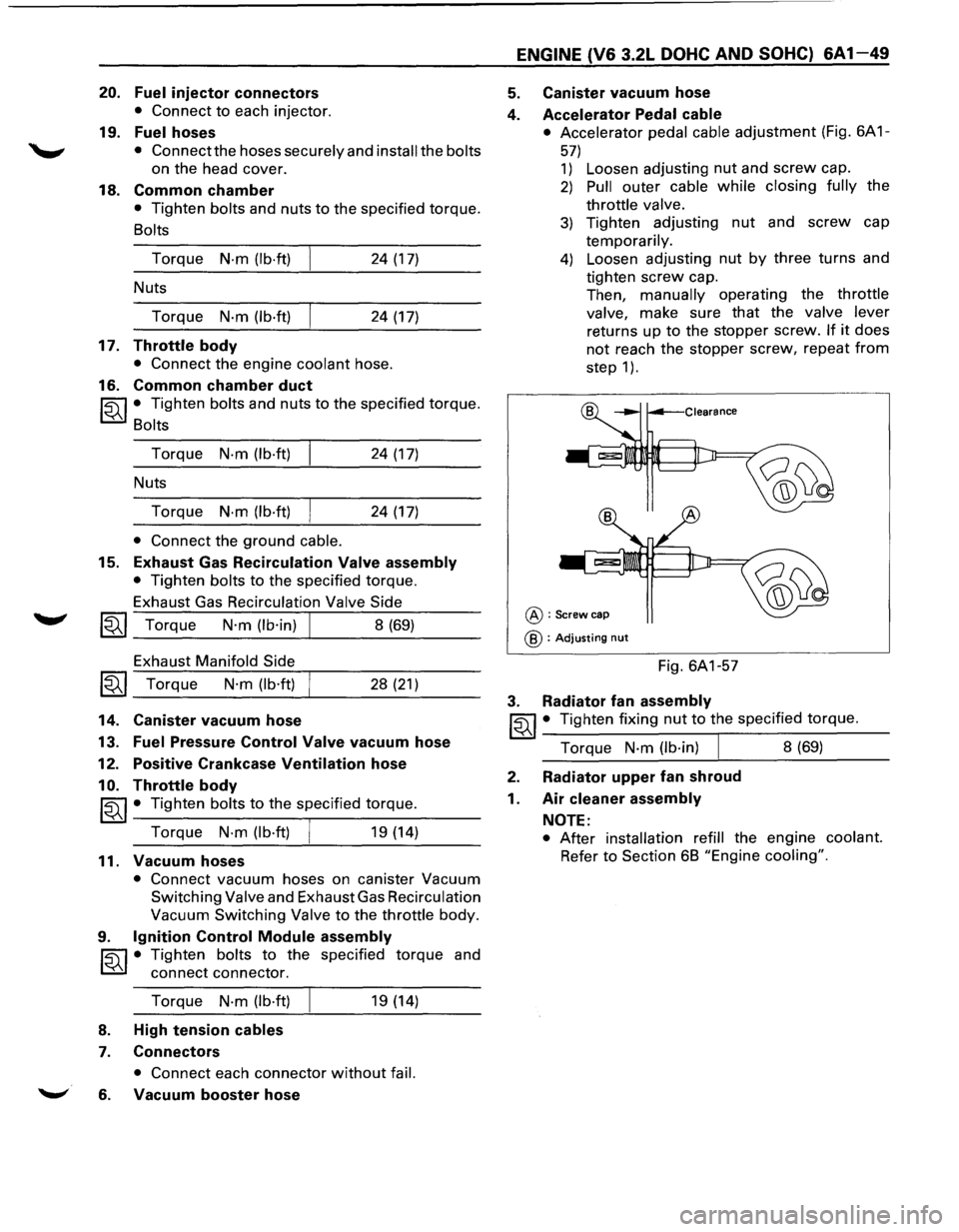
4. Accelerator Pedal
cable
• Accelerator pedal cable adjustment (Fig. 6A 1-
57)
1) Loosen adjusting nut and screw cap.
2) Pull outer cable while closing fully the
throttle valve.
3) Tighten adjusting nut and screw cap
temporarily.
4) Loosen adjusting nut by three turns and
tighten
screw cap.
Then,
manually operating the throttle
valve,
make sure that the valve lever
returns up to the stopper screw. If it does
not reach the stopper screw, repeat from
step 1 ).
@:Screw cap
@ : Adjusting nut
Fig. 6A1-57
3. Radiator fan assembly
~~~· Tighten fixing nut to the specified torque.
Torque
N-m (lb·in) I 8 (69)
2. Radiator upper fan shroud
1. Air cleaner assembly
NOTE:
• After installation refill the engine coolant.
Refer to Section 6B "Engine cooling".
Page 613 of 1928
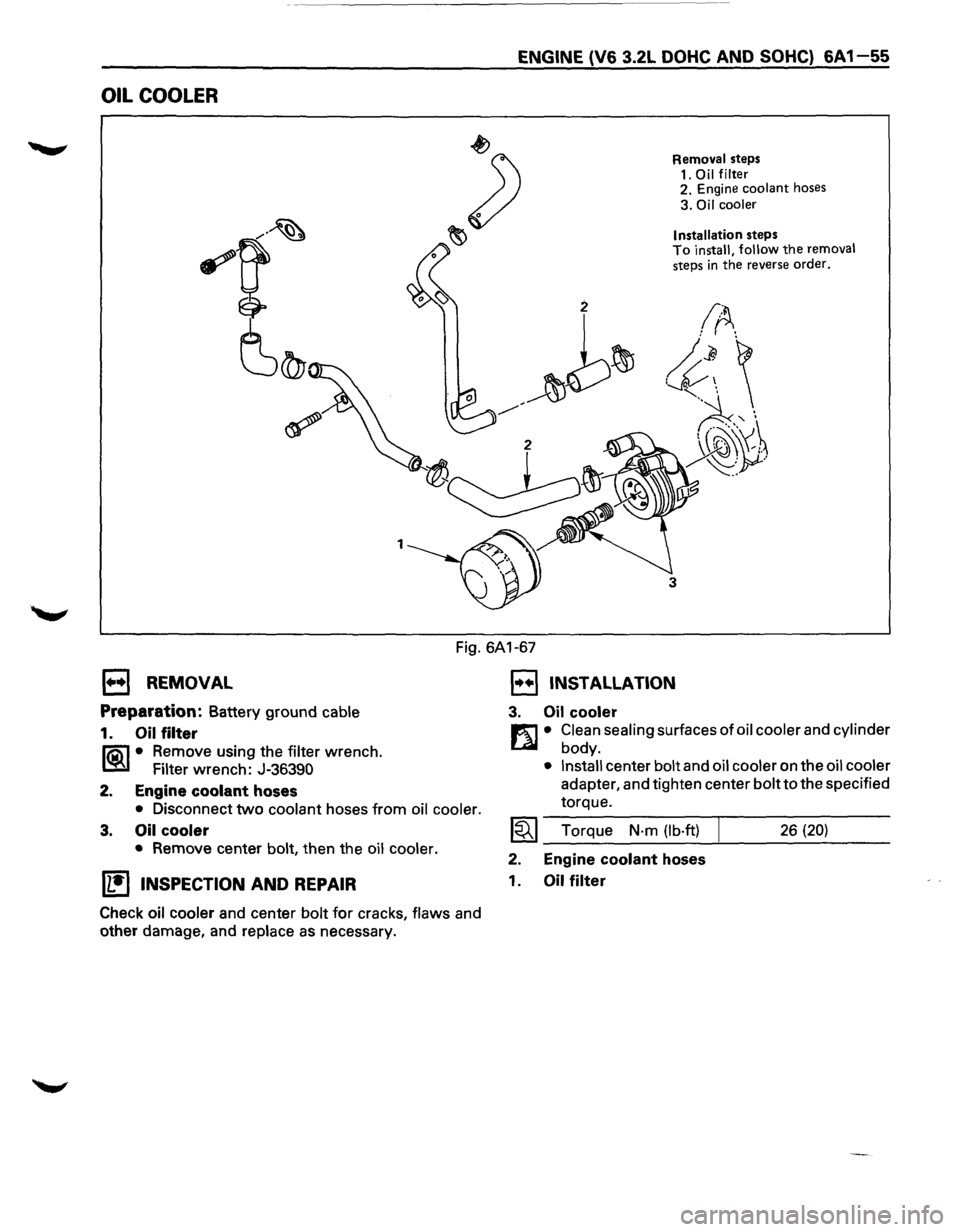
OIL COOLER
1
ENGINE (V6 3.2L DOHC AND SOHC) 6A 1-55
Removal steps
1.
Oil filter 2. Engine coolant hoses
3. Oil cooler
Installation
steps To install, follow the removal steps in the reverse order.
3
Fig. 6A1-67
1••1 REMOVAL
Preparation: Battery ground cable
1. Oil filter
li5\1 • Remove using the filter wrench.
~ Filter wrench: J-36390
2. Engine
coolant hoses
• Disconnect two coolant hoses from oil cooler.
3. Oil cooler
• Remove center bolt, then the oil cooler.
U!)INSPECTION AND REPAIR
Check oil cooler and center bolt for cracks, flaws and
other damage, and
replace as necessary.
1••1 INSTALLATION
3. Oil cooler
m • Clean sealing surfaces of oil cooler and cylinder
L41 body.
• Install center bolt and oil cooler on the oil cooler
adapter, and tighten center bolt to the specified
torque.
~~~ Torque N·m (lb·ft) 26 (20)
2. Engine coolant hoses
1.
Oil filter
Page 620 of 1928
'.n
6A1-62 ENGINE (V6 3.2L DOHC AND SOHC)
E) REMOVAL
Preparation: • Disconnect battery ground cable.
• Remove engine hood.
In order to return the hood to the
original position exactly, make
alignment on the hood and hinges
before
removal.
•
Drain radiator coolant.
1. Accelerator cable
• Disconnect from throttle valve and common
chamber.
2. Ventilation hose
3.
Air hose
4. Air cleaner assembly
5. Canister vacuum hose
6. Vacuum booster hose
7. Engine harness connectors
• Disconnect three connectors on canister side.
8. Battery ground cables
• Disconnect two black and white connector
clips
from the power steering pump bracket.
9. Ground cables
• Disconnect two terminals connected to the
battery support and the
front right frame.
1 0. Bonding cable connector
• Disconnect connector on the left side dash
panel.
11. Bonding cable terminal
• Disconnect terminal on the back of left bank.
12. Starter harness connector
• Disconnect from starter.
13. Radiator
• Disconnect upper and lower hoses from the
engine.
• Disconnect coolant reserve tank hose from
radiator.
• Disconnect ATF hose from the pipe. (A/T)
• Remove radiator lower hose clip from the hose
bracket.
• Remove radiator lower fan shroud.
• Remove radiator.
14. Power steering pump drive belt
15. Power steering pump
• Remove two bolts on the bracket, and place the
pump along with piping on the body side.
16. Air Conditioning compressor drive belt
17. Air Conditioning compressor
• Remove fixing bolts and shift aside the
compressor
with piping attached.
18. Heater hoses
• Disconnect two hoses from the engine.
19. ATF pipes
• Disconnect two pipes from right side engine
mount.
20. Transmission assembly
• See "Transmission Removal and Installation"
in Section 7.
21. Left side engine mount
• Support the engine.
• Remove two fixing bolts from engine mount on
chassis side.
22. Right side engine mount
• Remove two fixing bolts from engine mount on
chassis side.
23. Engine assembly
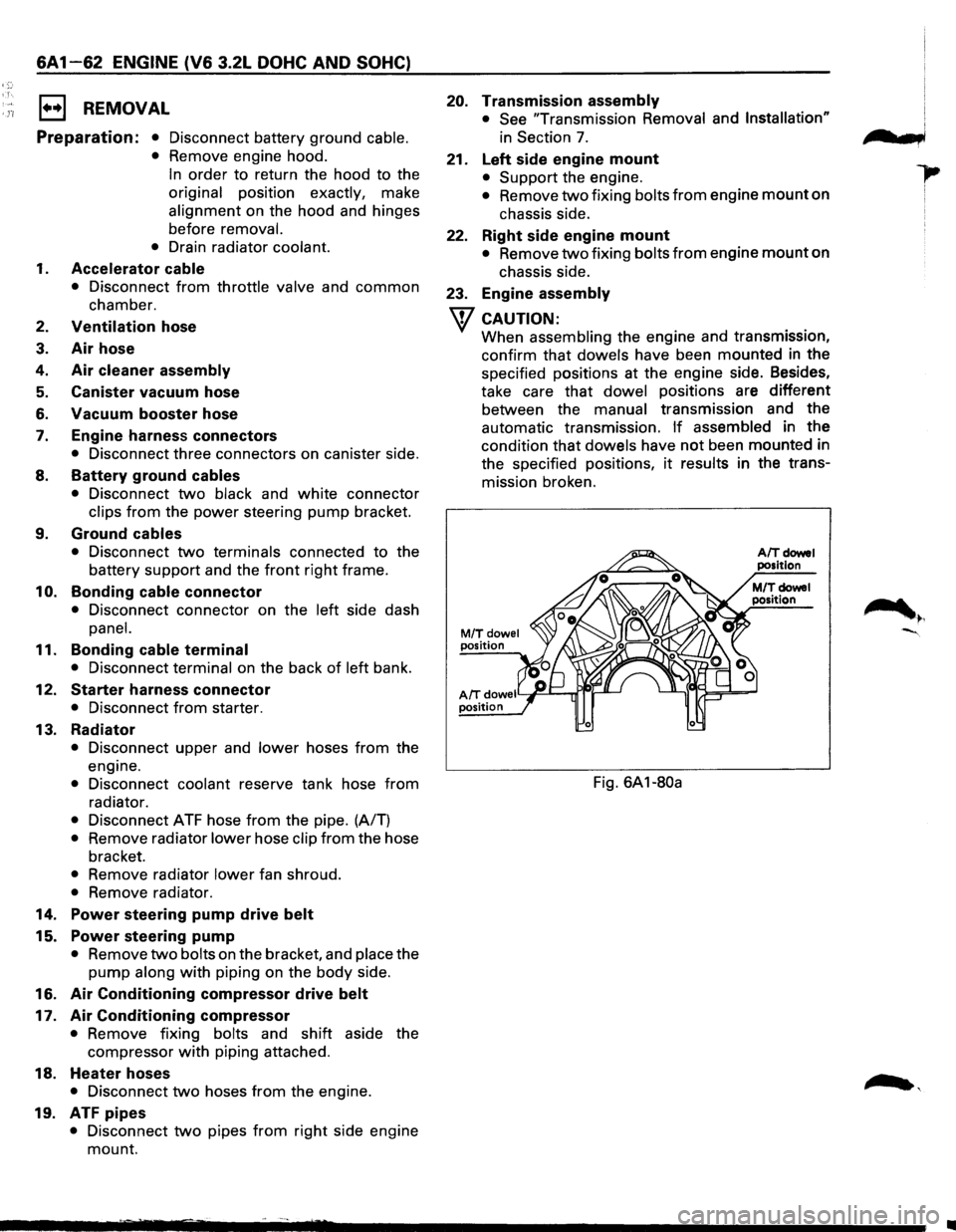
w CAUTION:
When assembling the engine and transmission,
confirm
that dowels have been mounted in the
specified positions at the engine side. Besides,
take care
that dowel positions are different
between the manual transmission and the
automatic transmission.
If assembled in the
condition that dowels have not been mounted in
the specified positions,
it results in the trans
mission broken.
M/Tdowel position
AIT doweiY~--r..ri~-' position
Fig. 6A1-80a
n t b,
•