fog light bulb ISUZU TROOPER 1995 Workshop Manual
[x] Cancel search | Manufacturer: ISUZU, Model Year: 1995, Model line: TROOPER, Model: ISUZU TROOPER 1995Pages: 1928
Page 1191 of 1928

CHASSIS ELECTRICAL 8-1
·SECTION 8
CHASSIS ELECTRICAL
'\f CAUTION: .
When fasteners are removed, always reinstall them at the same location from which they were removed.
If a fastener needs to be replaced, use the correct part number fastener for that application. If the correct
part number fastener is not
available, a fastener of equal size and strength (or stronger) may be used.
Fasteners that are not reused, and those requiring thread
locking compound, will be called out. The correct
torque
values must be used when installing fasteners that require it. If the above conditions are not
followed, parts or system damage could result.
CONTENTS
General Information .................................... 8-2
Notes for Working on Electrical
Items .................................................... 8-2
Symbols and Abbreviations ................. 8-8
Symbols ............................................ 8-8
Abbreviations ................................... 8-9
Parts for Electrical Circuit ..................... 8-10
Wiring ............................................... 8-10
Fuse .................................................. 8-11
Fusible Link ....................................... 8-12
Circuit Breaker ................................... 8-12
Relay ................................................. 8-12
Relay Specifications and
Configurations ................................ 8-13
Diode ................................................. 8-14
Connector ......................................... 8-15
Reading the Circuit Diagram ................ 8-17
Main Data and Specifications .................... 8-19
Bulb Specifications ................................ 8-19
Fuse,
Fusible Link and
Circuit Breaker Location ..................... 8-21
Fuse
Block Circuit .................................. 8-22
Reference Table of Fuse, Fusible
Link and Circuit Breaker ..................... 8-23
Relay Location ....................................... 8-27
Diode Location .......................................
8-28
Grounding Point .................................... 8-29
Reference Table ................................ 8-29
Location ............................................ 8-31
Cable Harness Routing .......................... 8-34
System Repair .............................................. 8-38
Start and Charging ................................ 8-38
Engine Control Module
(ECM) ................................................... 8-47
Headlight and Fog Light ........................ 8-58
Front Side Marker Light, Parking Light,
Taillight, License Plate Light and
Illumination Light .............................. 8-76
Stoplight and Rear Defogger .............. 8-92
Turn Signal Light, Hazard
Warning
Light, Cornering Light,
Backup
Light and Horn ..................... 8-106
Dome Light, Luggage room Light,
Courtesy Light, Map Light,
Seat Belt Switch and
Warning Buzzer ................................. 8-128
Power Door Lock ................................. 8-142
Power
Window .................................... 8-156
Cruise
Control ...................................... 8-172
Anti-Lock Brake
System (ABS) ........... 8-178
Rear
Wheel Anti-Lock Brake
System (RWAL) ................................. 8-185
Transmission
Control Module
(TCM) ................................................. 8-192
A/T Shift Lock ...................................... 8-200
Windshield
Wiper/Washer and
Rear
Wiper/Washer .......................... 8-205
Headlight wiper /washer ..................... 8-232
Audio, Auto Antenna,
Cigarette
Lighter and digital clock ... 8-246
Power Door Mirror ............................... 8-254
Anti-theft System ................................ 8-270
Meter and Warning/Indicator Light ... 8-288
A/T Shift Indicator ............................... 8-336
Heater and
Air Conditioning ............... 8-340
Sun
Roof ............................................... 8-346
Power Seat ........................................... 8-360
Seat
Heater .......................................... 8-37 4
Supplemental Restraint
System (SRS) -AIR BAG ................... 8-382
Page 1209 of 1928
CHASSIS ELECTRICAL 8-19
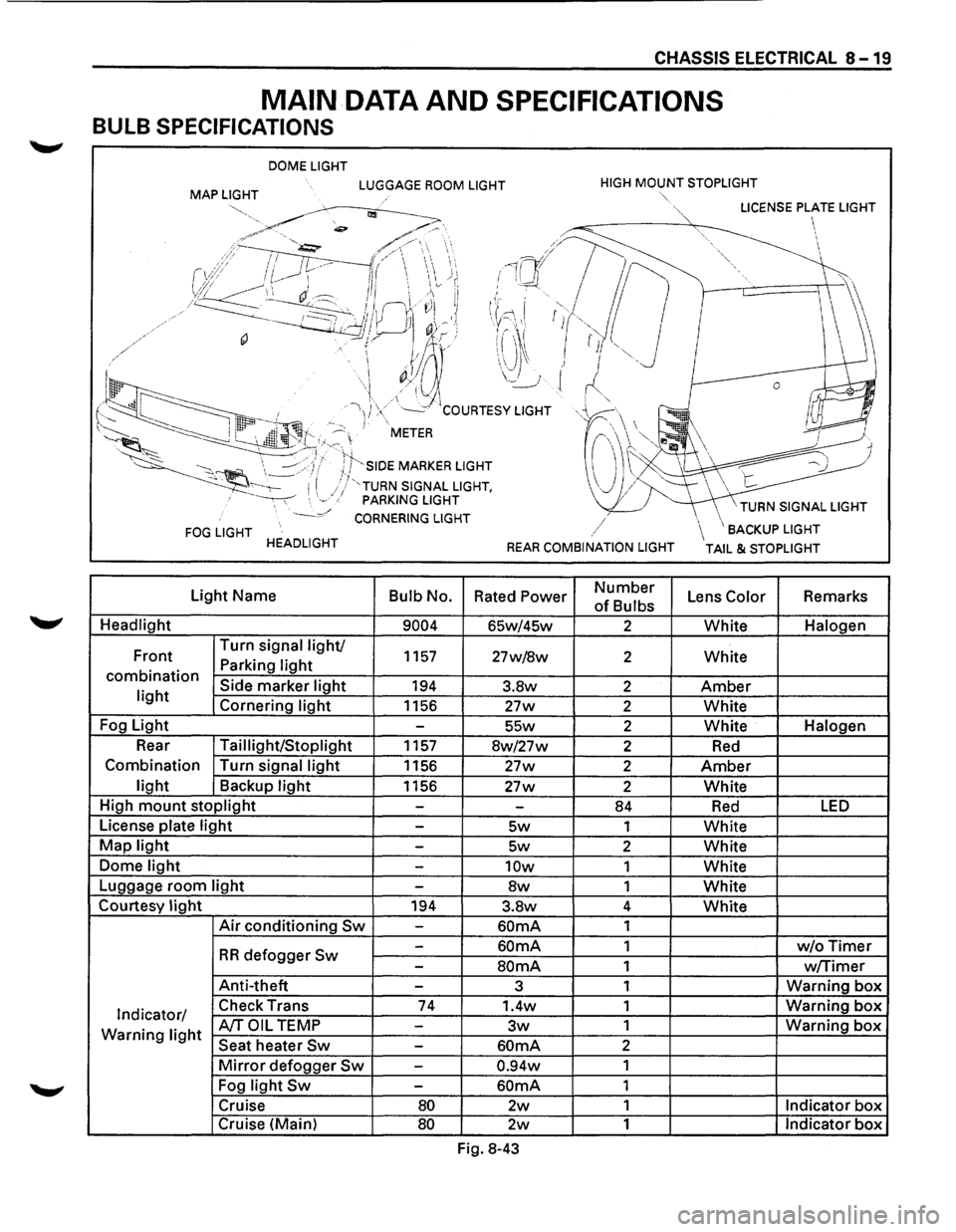
MAIN DATA AND SPECIFICATIONS
BULB SPECIFICATIONS
DOME LIGHT
MAP LIGHT LUGGAGE ROOM LIGHT HIGH MOUNT STOPLIGHT
FOG LIGHT HEADLIGHT
Light Name
Bulb No.
Headlight
9004
Front Turn
signal light/ 1157 Parking light combination Side marker light 194 light Cornering light 1156
Fog Light
-
Rear Taillight/Stoplight 1157
Combination Turn signal
light 1156
light Backup light 1156
High
mount stoplight -
License plate light -
Map light -
Dome light -
Luggage room light -
Courtesy light 194
Air conditioning Sw -
-
RR defogger Sw -
Anti-theft -
Indicator/ Check
Trans 74
Warning light A/TOIL TEMP -
Seat heater Sw -
Mirror defogger Sw -
Fog light Sw -
Cruise 80
Cruise (Main) 80
""·
,/
REAR COMBINATION LIGHT
Rated Power Number
of Bulbs
65w/45w 2
27w/8w 2
3.8w 2
27w 2
55w 2
8w/27w 2
27w 2
27w 2
-84
5w 1
5w 2
10w 1
8w 1
3.8w 4
60mA 1
60mA 1
SOmA 1
3 1
1.4w 1
3w 1
60mA 2
0.94w 1
60mA 1
2w 1
2w 1
Fig. 8-43
\BACKUP LIGHT
TAIL & STOPLIGHT
Lens Color Remarks
White Halogen
White
Amber
White
White Halogen
Red
Amber
White
Red LED
White
White
White
White
White
w/oTimer
w/Timer
Warning box
Warning box
Warning box
Indicator box
Indicator box
Page 1210 of 1928
8-20 CHASSIS ELECTRICAL
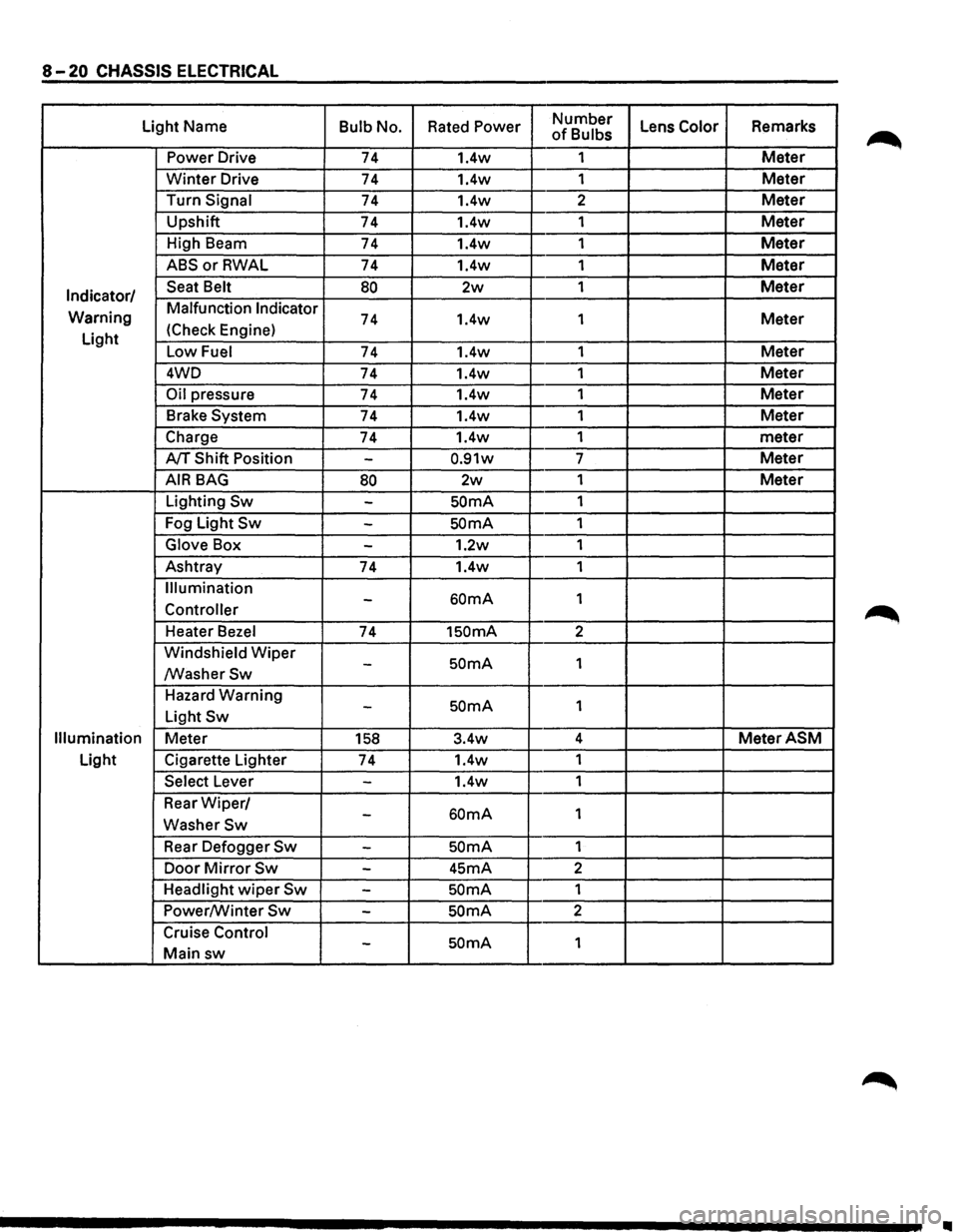
Light Name Bulb No. Rated Power Number Lens Color Remarks of Bulbs
Power Drive 74 1.4w 1
Meter
Winter Drive 74 1.4w
1 Meter
Turn Signal 74 1.4w 2 Meter
Upshift
74 1.4w 1 Meter
High Beam
74 1.4w 1 Meter
ABSorRWAL 74 1.4w 1 Meter
Indicator/ Seat Belt 80 2w 1 Meter
Warning Malfunction Indicator 74 1.4w
1 Meter
Light (Check
Engine)
Low Fuel 74 1.4w 1 Meter
4WD
74 1.4w 1 Meter
Oil pressure 74 1.4w 1 Meter
Brake System 74 1.4w 1 Meter
Charge 74 1.4w 1
meter
A/T Shift Position -0.91w 7 Meter
AIR BAG 80 2w 1 Meter
Lighting Sw -SOmA 1
Fog Light
Sw -SOmA 1
Glove Box -1.2w 1
Ashtray
74 1.4w 1
Illumination
60mA 1 -Controller
Heater Bezel 74 1SOmA 2
Windshield
Wiper SOmA 1 -/WasherSw
Hazard Warning SOmA 1 -Light Sw
Illumination Meter 158 3.4w 4 MeterASM
Light
Cigarette Lighter
74 1.4w
1
Select Lever -1.4w 1
Rear
Wiper/ 60mA 1 -WasherSw
Rear Defogger Sw -SOmA 1
Door
Mirror Sw -45mA 2
Headlight
wiper Sw -SOmA 1
Power/Winter
Sw -SOmA 2
Cruise Control
SOmA 1 -Main sw
II
Page 1252 of 1928
8-62 CHASSIS ELECTRICAL
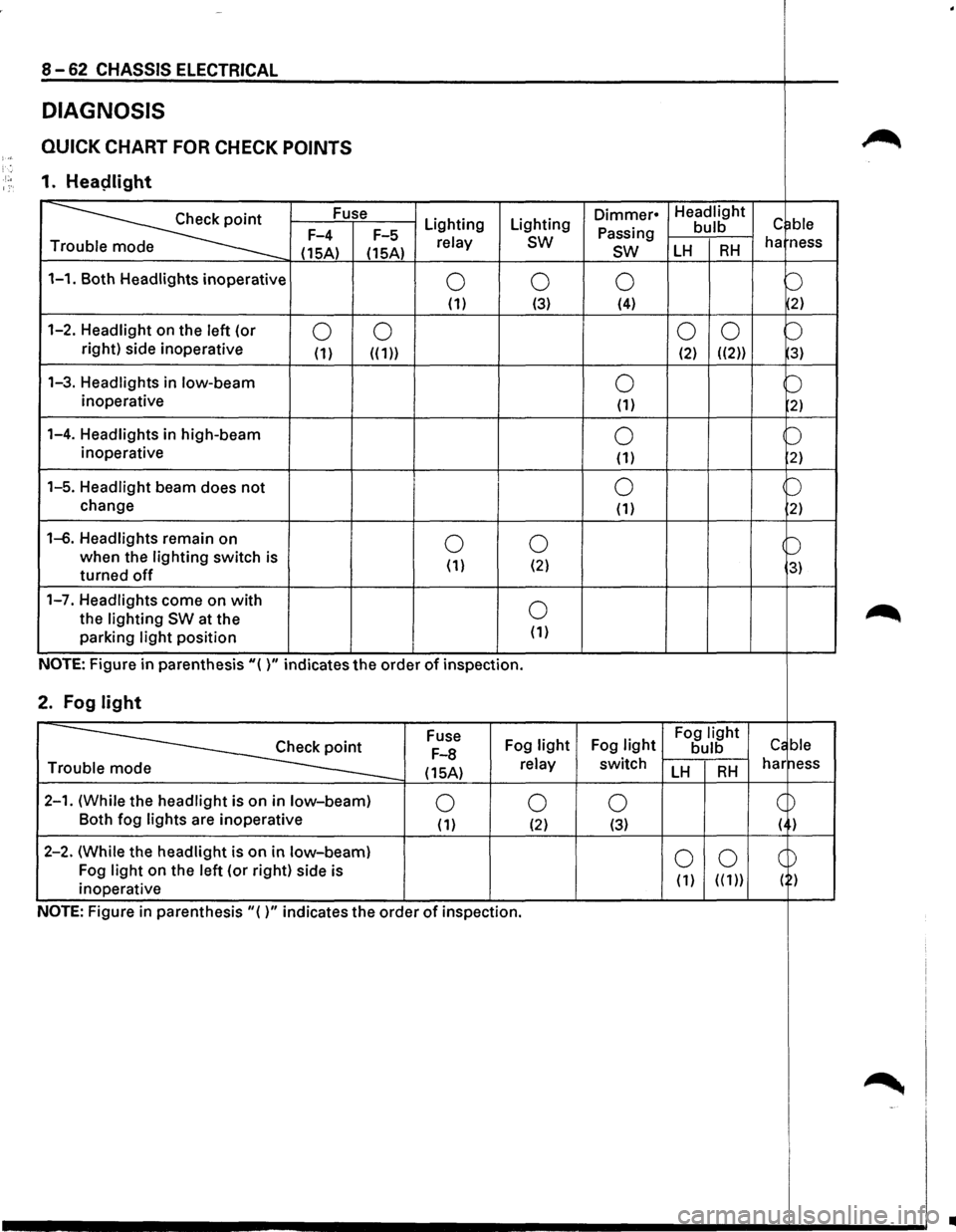
DIAGNOSIS
QUICK CHART FOR CHECK POINTS ~ )-; '. ·'·• 1. Heaplight 1:·
~
Fuse Lighting Lighting Dimmer• Headlight c ~ble Passing bulb F-4
F-5 relay sw ha ness
T
(15A) (15A) sw LH RH
1-1. Both Headlights inoperative 0 0 0 b (1) (3) (4) 2)
1-2. Headlight on
the left (or 0 0 0
0 b right) side inoperative (1) ((1)) (2) ((2)) 3)
1-3. Headlights in low-beam 0 b inoperative (1) 2)
1-4. Headlights in high-beam 0 b inoperative
(1) 2)
1-5. Headlight beam does not 0 p
change (1) 2)
1-6. Headlights remain on 0 0 b when the lighting switch is
( 1) (2) 3) turned off
1-7. Headlights come on with 0 ~ the lighting SW at the
parking light position (1)
NOTE: Figure in parenthesis"( )" indicates the order of inspection.
2. Fog light
~
Fuse
Fog light Fog light Fog light Cc ble F-8 bulb
(15A) relay switch LH RH har ness Tr
2-1. (While the headlight is on in low-beam) 0 0 0 c ~ Both
fog lights are inoperative (1) (2) (3) ( )
2-2. (While the headlight is
on in low-beam) 0 0 CD Fog light on the left (or right) side is
( 1) ( ( 1)) ( ) inoperative
NOTE: Figure
in parenthesis"()" indicates the order of inspection.
~ -'
..
Page 1258 of 1928
8-68 CHASSIS ELECTRICAL
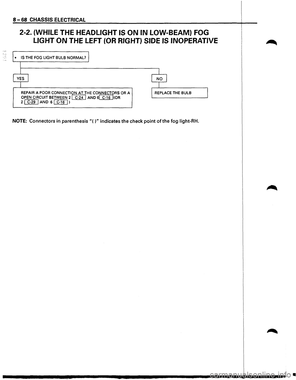
2-2. (WHILE THE HEADLIGHT IS ON IN LOW-BEAM) FOG
LIGHT
ON THE LEFT (OR RIGHT) SIDE IS INOPERATIVE
• IS THE FOG LIGHT BULB NORMAL?
I
I
YES I
I
REPAIR A POOR CONNECTION AT THE CONNECTORS OR A OPEN CIRCUIT BETWEEN 2 WU AND 6~(0R 2~AND 6[f}[]l
I
I NO I
I
l REPLACE THE BULB
NOTE: Connectors in parenthesis"()" indicates the check point of the fog light-RH.
I
•
Page 1263 of 1928
CHASSIS ELECTRICAL 8-73
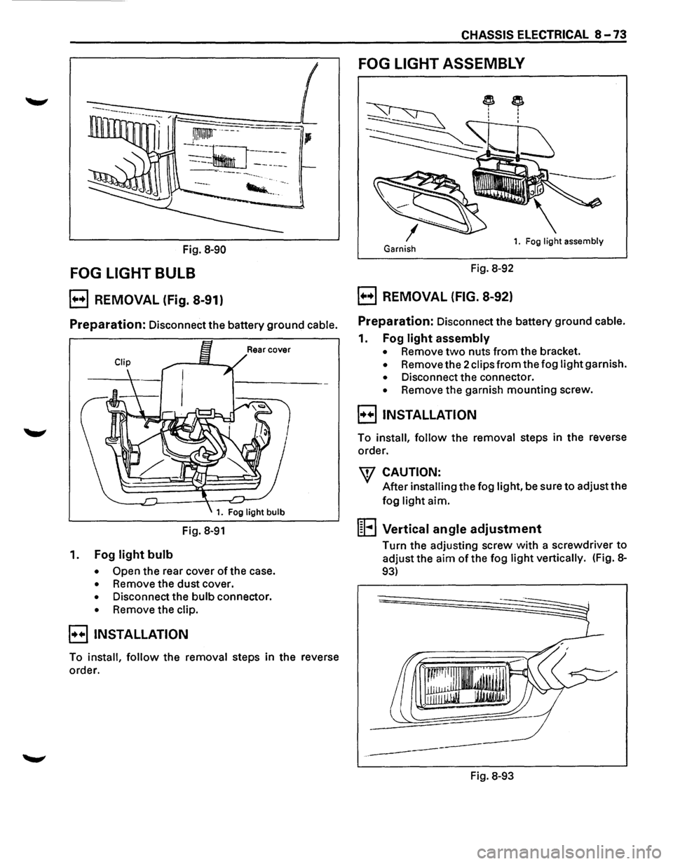
FOG LIGHT ASSEMBLY
~ I : I
Fig. 8-90 Garnish 1. Fog light assembly
FOG LIGHT BULB Fig. 8-92
B REMOVAL (Fig. 8-91) B REMOVAL (FIG. 8-92)
Preparation: Disconnect the battery ground cable. Preparation: Disconnect the battery ground cable.
Fig. 8-91
1. Fog light bulb
• Open the rear cover of the case.
• Remove the dust cover.
• Disconnect the bulb connector.
• Remove the clip.
EJINSTALLATION
To install, follow the removal steps in the reverse
order.
1. Fog light assembly
• Remove two nuts from the bracket.
• Remove the 2 clips from the fog light garnish.
• Disconnect the connector.
• Remove the garnish mounting screw.
B INSTALLATION
To install, follow the removal steps in the reverse
order.
\V CAUTION:
After installing the fog light, be sure to adjust the
fog light aim.
1~1 ... 1 Vertical angle adjustment
Turn the adjusting screw with a screwdriver to
adjust the aim of the fog light vertically. (Fig. 8-
93)
1r~~·~··.l J.li' . WlliJ
-'I IJIJJ
---
-------
Fig. 8-93
Page 1264 of 1928
8-74 CHASSIS ELECTRICAL
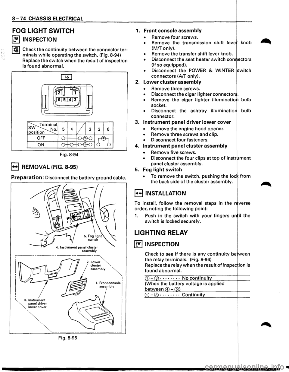
FOG LIGHT SWITCH
~ INSPECTION
I tgj Check the continuity between the connector ter
minals
while operating the switch. (Fig. 8-94)
Replace the switch when the result of inspection
is found abnormal.
ru~
IT
2 [II
161514131
c-
Fig. 8-94
B REMOVAL (FIG. 8-95)
TI ';
Preparation: Disconnect the battery ground cable.
Fig.
8-95
I I 1. Front console I assembly
1. Front console assembly
• Remove four screws.
• Remove the transmission shift leve knob
(M!r only).
• Remove the transfer shift lever knob.
• Disconnect the seat heater switch con ectors
(If so equipped).
• Disconnect the POWER & WINTER switch
connectors
(A/T only).
2.
Lower cluster assembly
• Remove three screws.
• Disconnect the cigar lighter connector .
• Remove the cigar lighter illuminatio bulb
socket.
• Disconnect the ashtray illuminatio bulb
connector.
3.
Instrument panel driver lower cover
• Remove the engine hood opener.
• Remove three screws and clip.
• Disconnect four fasteners.
4.
Instrument panel cluster assembly
• Remove five screws.
• Disconnect the four clips at top of instr ment
panel cluster assembly.
5. Fog
light switch
• To remove the switch, pushing the loc from
the back side of the cluster assembly.
B INSTALLATION
To install, follow the removal steps in the r verse
order, noting the
following point:
1. Push in the switch with your fingers un il the
switch is locked securely.
LIGHTING RELAY
~ INSPECTION
Check to see if there is any continuity be ween
the relay terminals. (Fig.
8-96)
Replace the relay when the result of in spec ion is
found abnormal.
CD-3 · · · · • · · · No continuit
(When the battery voltage is applied
between
4 -s)
•
Page 1286 of 1928
8-96 CHASSIS ELECTRICAL
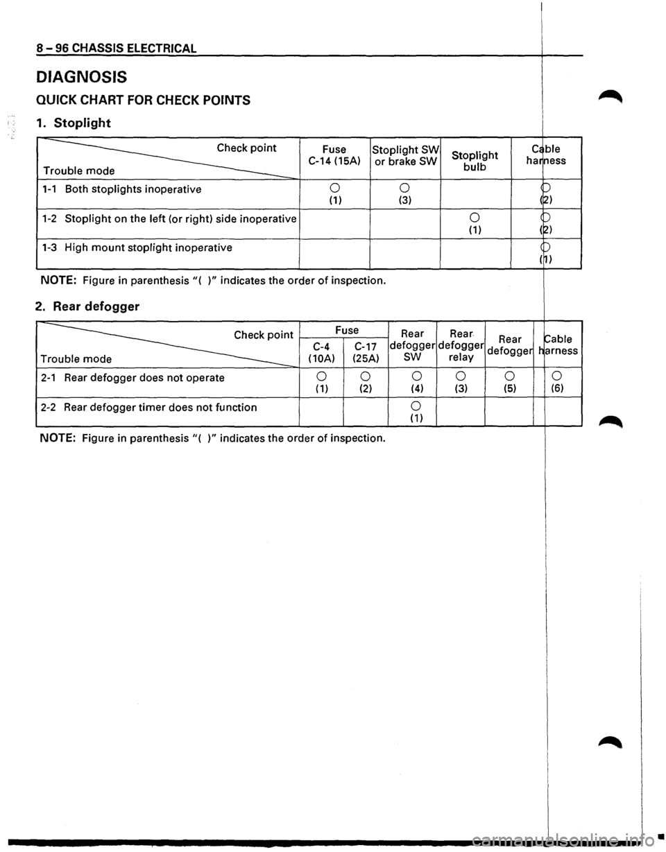
DIAGNOSIS
QUICK CHART FOR CHECK POINTS
1. Stoplight
~
Fuse Stoplight SW Stoplight c~ ble
C-14 (15A) or brake SW bulb har
ness
Tr
1-1 Both stoplights inoperative 0 0 p
(1) (3) (~)
1-2 Stoplight on the left (or right) side inoperative 0 )
(1) (2)
1-3 High mount stoplight inoperative )
( 1)
NOTE: Figure in parenthesis"( )" indicates the order of inspection.
2. Rear defogger
~·
Fuse
Rear Rear ~able C-4
C-17 defogger defogger Rear
Tr
(10A) (25A) sw relay defogger
harness
2-1 Rear defogger does not operate 0 0 0 0 0
0 ( 1) (2) (4) (3) (5) (6)
2-2 Rear
defogger timer does not function 0 (1)
NOTE: Figure in parenthesis"( )" indicates the order of inspection.
•
Page 1312 of 1928
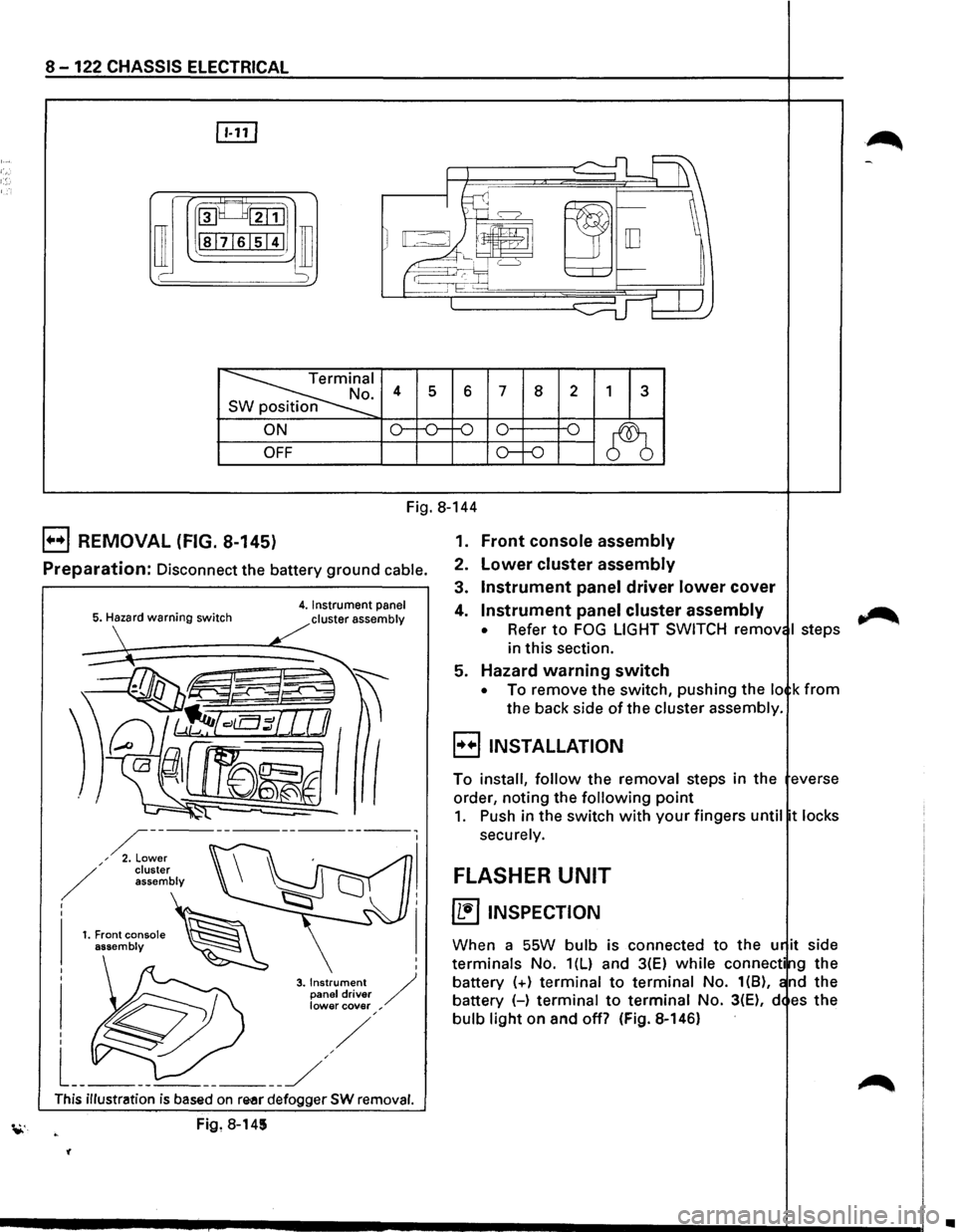
8-122 CHASSIS ELECTRICAL
rn
~~:::1
ill I -
~I . 4 s 6 7 8 2 1 3 n
ON o--o-f-0 0 -o
~ OFF o--o
Fig. 8-144
B REMOVAL (FIG. 8-145)
Preparation: Disconnect the battery ground cable.
5. Hazard warning switch 4. Instrument panel
cluster assembly
I
I
3. Instrument / panel driver lower cover ,
This illustration is based on re-ar defogger SW removal.
Fig, 8-145
'(
1. Front console assembly
2. Lower cluster assembly
3. Instrument panel driver lower cover
4. Instrument panel cluster assembly
• Refer to FOG LIGHT SWITCH remov I steps
in this section.
5. Hazard warning switch
• To remove the switch, pushing the lo k from
the back side of the cluster assembly.
B INSTALLATION
To install, follow the removal steps in the everse
order, noting the
following point
1. Push in the switch with your fingers until t locks
securely.
FLASHER UNIT
~ INSPECTION
When a SSW bulb is connected to the u it side
terminals No. 1(L) and 3(E) while connecti g the
battery
(+) terminal to terminal No. 1(8), nd the
battery (-)
terminal to terminal No. 3(E), d es the
bulb light on and off? (Fig. 8-146)
~
•