gas type ISUZU TROOPER 1995 User Guide
[x] Cancel search | Manufacturer: ISUZU, Model Year: 1995, Model line: TROOPER, Model: ISUZU TROOPER 1995Pages: 1928
Page 692 of 1928
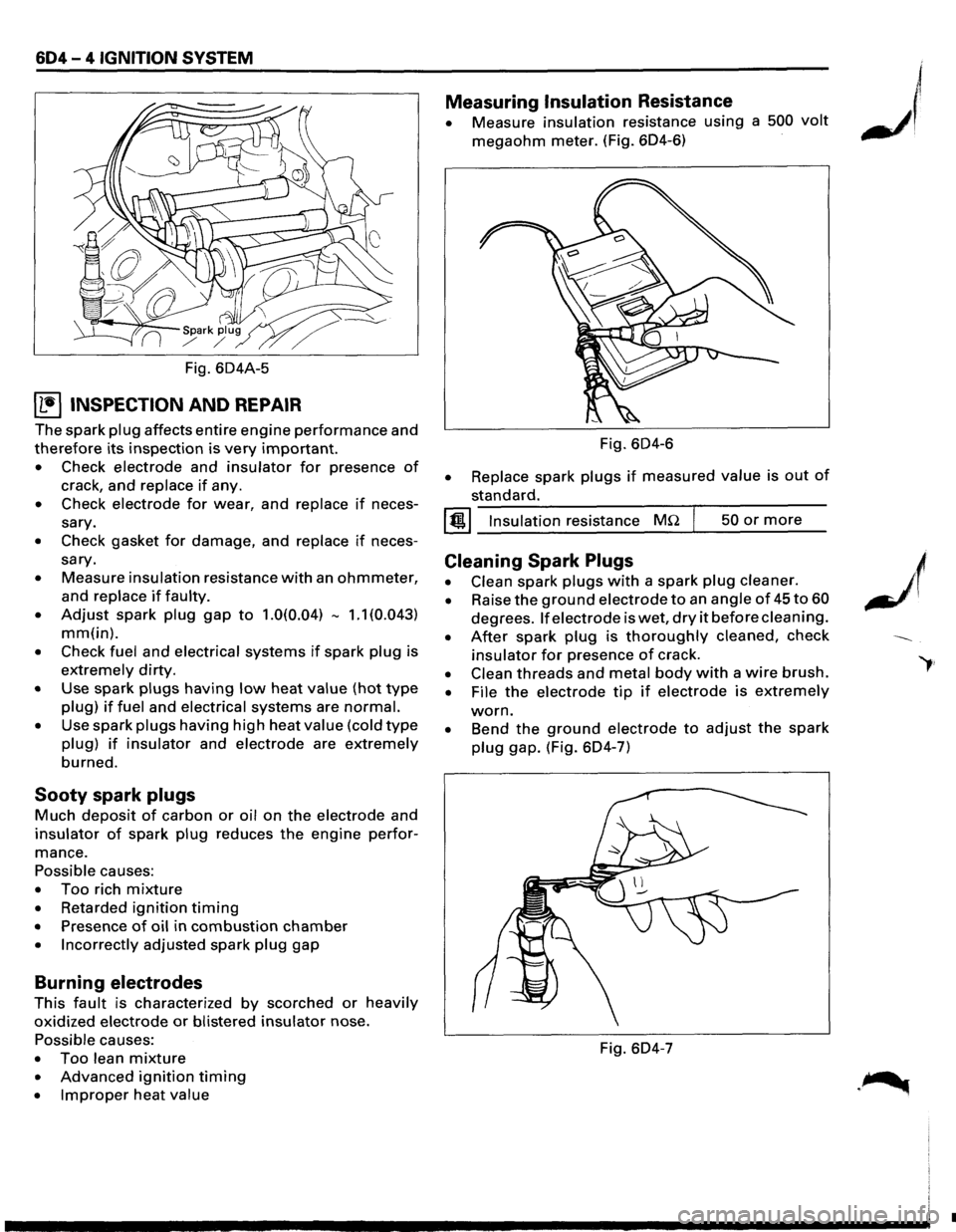
604-4 IGNITION SYSTEM
Fig. 604A-5
~ INSPECTION AND REPAIR
The spark plug affects entire engine performance and
therefore its inspection is very important.
• Check electrode and insulator for presence of
crack, and replace if any.
• Check electrode for wear, and replace if neces
sary.
• Check gasket for damage, and replace if neces
sary.
• Measure insulation resistance with an ohmmeter,
and replace if faulty.
• Adjust spark plug gap to 1.0(0.04) -1.1 (0.043)
mm(in).
• Check fuel and electrical systems if spark plug is
extremely dirty.
• Use spark plugs having low heat value (hot type
plug) if fuel and electrical systems are normal.
• Use spark plugs having high heat value (cold type
plug) if insulator and electrode are extremely
burned.
Sooty spark plugs
Much deposit of carbon or oil on the electrode and
insulator of spark plug reduces the engine perfor
mance.
Possible causes:
• Too rich mixture
• Retarded ignition timing
• Presence of oil in combustion chamber
• Incorrectly adjusted spark plug gap
Burning electrodes
This fault is characterized by scorched or heavily
oxidized electrode or blistered insulator nose.
Possible causes:
• Too lean mixture
• Advanced ignition timing
• Improper heat value
Measuring Insulation Resistance
• Measure insulation resistance using a 500 volt
megaohm meter. (Fig. 604-6)
Fig.
604-6
• Replace spark plugs if measured value is out of
standard.
I @!.j Insulation resistance MQ 50 or more
Cleaning Spark Plugs
• Clean spark plugs with a spark plug cleaner.
• Raise the ground electrode to an angle of 45 to 60
degrees. If electrode is wet, dry it before cleaning.
• After spark plug is thoroughly cleaned, check
insulator for presence of crack.
• Clean threads and metal body with a wire brush.
• File the electrode tip if electrode is extremely
worn.
• Bend the ground electrode to adjust the spark
plug gap. (Fig. 604-7)
Fig. 604-7
•
Page 707 of 1928
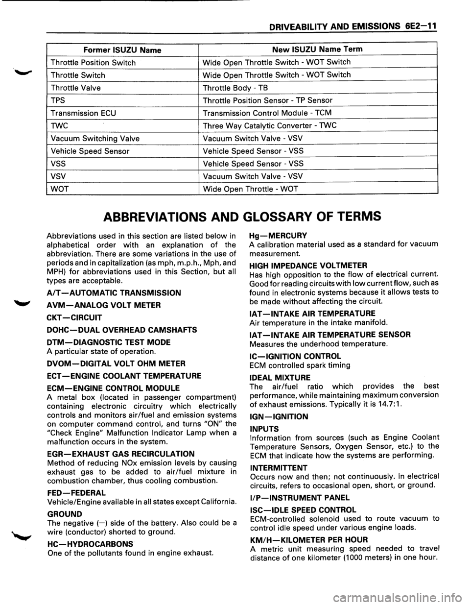
DRIVEABILITY AND EMISSIONS 6E2-11
Former ISUZU Name New ISUZU Name Term
Throttle Position Switch Wide Open Throttle Switch -WOT Switch
Throttle Switch
Wide Open Throttle Switch -WOT Switch
Throttle Valve Throttle
Body -TB
TPS Throttle Position Sensor -TP Sensor
Transmission ECU Transmission Control Module -TCM
TWC Three
Way
Catalytic Converter -TWC
Vacuum Switching Valve Vacuum Switch Valve -VSV
Vehicle Speed Sensor Vehicle
Speed Sensor
-VSS
vss Vehicle Speed Sensor -VSS
vsv Vacuum Switch Valve -VSV
WOT
Wide Open Throttle -WOT
ABBREVIATIONS AND GLOSSARY OF TERMS
Abbreviations used in this section are listed below in
alphabetical order with an explanation of the
abbreviation. There are some variations in the use
of
periods and in capitalization (as mph, m.p.h., Mph, and
MPH) for abbreviations used in this Section, but all
types are acceptable.
A/T -AUTOMATIC TRANSMISSION
AVM-ANALOG VOLT METER
CKT -CIRCUIT
DOHC-DUAL OVERHEAD CAMSHAFTS
DTM-DIAGNOSTIC TEST MODE
A particular state of operation.
DVOM-DIGITAL VOLT OHM METER
ECT -ENGINE COOLANT TEMPERATURE
ECM-ENGINE CONTROL MODULE
A metal box (located in passenger compartment)
containing
electronic circuitry which electrically
controls
and monitors air/fuel and emission systems
on
computer command control, and turns "ON" the
"Check Engine"
Malfunction Indicator Lamp when a
malfunction occurs in the system.
EGR-EXHAUST GAS RECIRCULATION
Method of reducing NOx emission levels by causing
exhaust gas
to be added to air/fuel mixture in
combustion chamber, thus
cooling combustion.
FED-FEDERAL
Vehicle/Engine available in all states except California.
GROUND
The negative (-) side of the battery. Also could be a
wire (conductor) shorted to ground.
HC-HVDROCARBONS
One of the pollutants found in engine exhaust.
Hg-MERCURV
A calibration material used as a standard for vacuum
measurement.
HIGH IMPEDANCE VOLTMETER
Has high opposition to the flow of electrical current.
Good
for reading circuits with low currentflow, such as
found in electronic systems because it allows tests to
be made without affecting the circuit.
IAT -INTAKE AIR TEMPERATURE
Air temperature in the intake manifold.
IAT-INTAKE AIR TEMPERATURE SENSOR
Measures the underhood temperature.
IC-IGNITION CONTROL
ECM controlled spark timing
IDEAL MIXTURE
The air/fuel ratio which provides the best
performance,
while maintaining maximum conversion
of exhaust emissions. Typically it is 14.7:1.
IGN-IGNITION
INPUTS
Information from sources (such as Engine Coolant
Temperature Sensors, Oxygen Sensor, etc.) to the
ECM that indicate how the systems are performing.
INTERMITTENT
Occurs now and then; not continuously. In electrical
circuits, refers to occasional open, short, or ground.
liP-INSTRUMENT PANEL
ISC-IDLE SPEED CONTROL
ECM-controlled solenoid used to route vacuum to
control idle speed under various engine loads.
KM/H-KILOMETER PER HOUR
A metric unit measuring speed needed to travel
distance of one kilometer (1 000 meters) in one hour.
Page 717 of 1928
DRIVEABILITY AND EMISSIONS 6E2-21
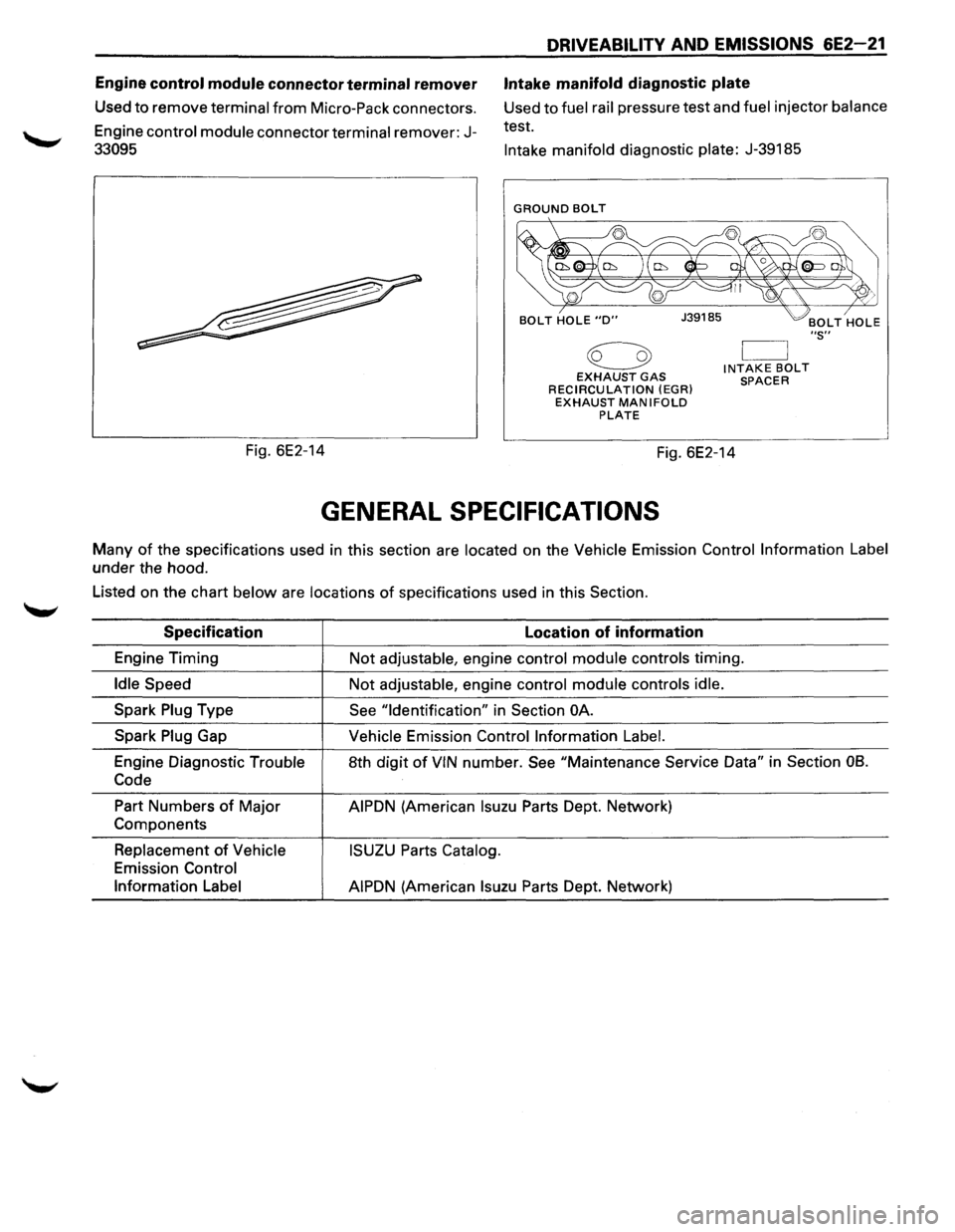
Engine control module connector terminal remover Intake manifold diagnostic plate
Used to remove terminal from Micro-Pack connectors.
Engine
control module connector terminal remover: J-
33095
Used to fuel rail pressure test and fuel injector balance
test.
Fig. 6E2-14
Intake manifold diagnostic plate: J-39185
GROUND BOLT
€3 EXHAUST GAS RECIRCULATION (EGR) EXHAUST MANIFOLD PLATE
INTAKE BOLT SPACER
Fig. 6E2-14
GENERAL SPECIFICATIONS
"S''
Many of the specifications used in this section are located on the Vehicle Emission Control Information Label
under the hood.
Listed on the chart
below are locations of specifications used in this Section.
Specification Location of information
Engine Timing
Not adjustable, engine control module controls timing.
Idle Speed Not adjustable, engine control module controls idle.
Spark Plug Type See "Identification" in Section OA.
Spark Plug Gap Vehicle Emission Control Information Label.
Engine Diagnostic Trouble 8th digit of VIN number. See "Maintenance Service Data" in Section 08.
Code
Part Numbers of Major AIPDN (American lsuzu Parts Dept. Network)
Components
Replacement of Vehicle ISUZU Parts Catalog.
Emission Control
Information Label
AIPDN
(American lsuzu Parts Dept. Network)
Page 797 of 1928
will not light when connected to the circuit. In some
cases, even an ordinary shop voltmeter
will not give an
accurate reading because its resistance is
too low.
Therefore, a 10 megohms input impedance digital
voltmeter is required to assure accurate voltage
readings.
The Engine
Control Module (ECM) controls output
circuits such as the fuel injectors, idle air control valve,
air conditioning clutch relay, etc. by controlling the
ground circuit through transistors
or a device called a
"quad-driver".
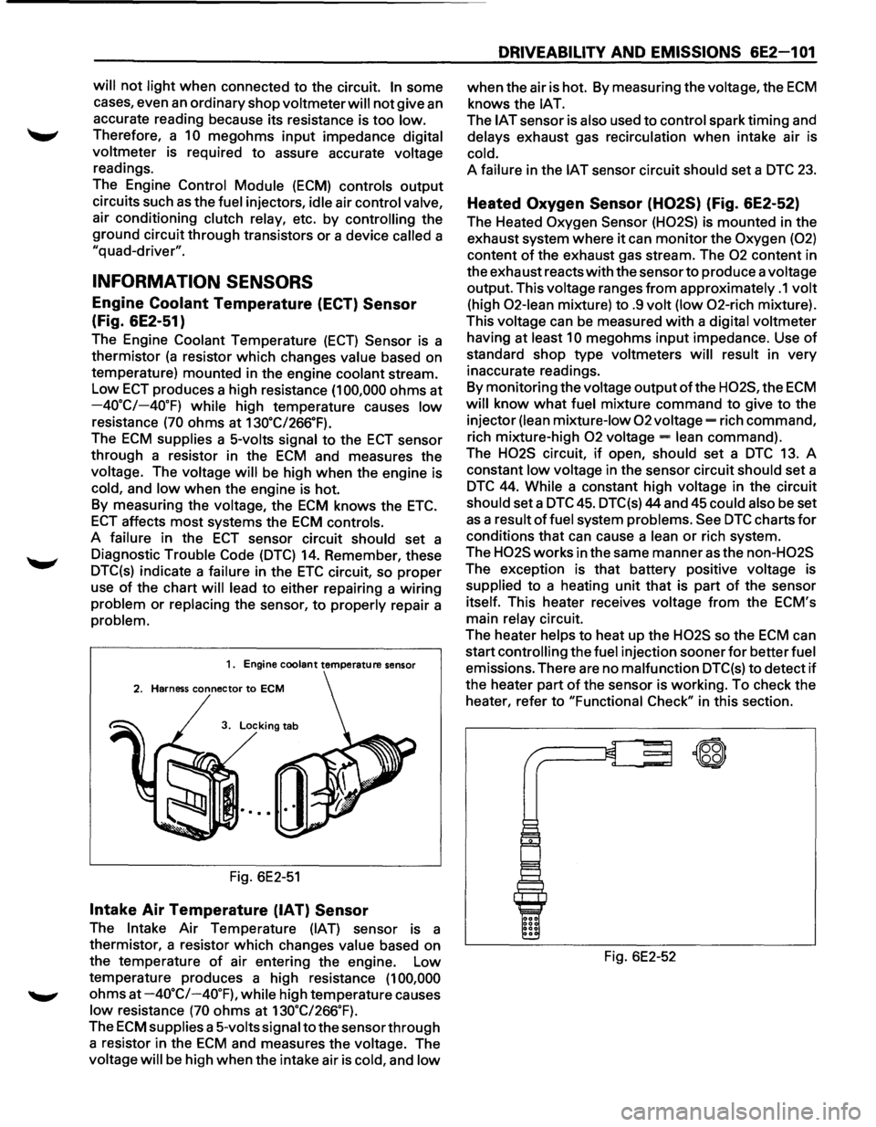
INFORMATION SENSORS
Engine Coolant Temperature (ECT) Sensor
(Fig. 6E2-51)
The Engine Coolant Temperature (ECT) Sensor is a
thermistor
(a resistor which changes value based on
temperature) mounted in the engine coolant stream.
Low ECT produces a high resistance (1 00,000 ohms at
-40.C/-40.F) while high temperature causes low
resistance (70 ohms at 130.C/266.F).
The ECM supplies a 5-volts signal to the ECT sensor
through a resistor in the
ECM and measures the
voltage. The voltage
will be high when the engine is
cold, and low when the engine is hot.
By measuring the voltage, the
ECM knows the ETC.
ECT affects most systems the ECM controls.
A failure in the
ECT sensor circuit should set a
Diagnostic Trouble Code
(DTC) 14. Remember, these
DTC(s) indicate a failure in the
ETC circuit, so proper
use
of the chart will lead to either repairing a wiring
problem or replacing the sensor, to properly repair a
problem.
1. Engine coolant temperature sensor
2. Harness connector to ECM
3. Locking tab
Fig. 6E2-51
Intake Air Temperature (IAT) Sensor
The Intake Air Temperature (IAT) sensor is a
thermistor, a resistor which changes
value based on
the temperature
of air entering the engine. Low
temperature produces a high resistance
(1 00,000
ohms at -4o·c/-40.F), while high temperature causes
low resistance (70 ohms at 130.C/266.F).
The ECM supplies a 5-volts signal to the sensor through
a resistor in the
ECM and measures the voltage. The
voltage
will be high when the intake air is cold, and low
DRIVEABILITV AND EMISSIONS 6E2-1 01
when the air is hot. By measuring the voltage, the ECM
knows the lAT.
The IAT sensor is also used to control spark timing and
delays exhaust gas recirculation when intake air is
cold.
A failure in the IAT sensor circuit should set a DTC 23.
Heated Oxygen Sensor (H02S) (Fig. 6E2-52)
The Heated Oxygen Sensor (H02S) is mounted in the
exhaust system where
it can monitor the Oxygen (02)
content of the exhaust gas stream. The 02 content in
the exhaust reacts
with the sensor to produce a voltage
output. This voltage ranges
from approximately .1 volt
(high 02-lean mixture) to .9 volt (low 02-rich mixture).
This voltage can
be measured with a digital voltmeter
having at
least 10 megohms input impedance. Use of
standard shop type voltmeters will result in very
inaccurate readings.
By monitoring the voltage
output ofthe H02S, the ECM
will know what fuel mixture command to give to the
injector
(lean mixture-low 02 voltage= rich command,
rich mixture-high
02 voltage= lean command).
The
H02S circuit, if open, should set a DTC 13. A
constant
low voltage in the sensor circuit should set a
DTC 44. While a constant high voltage in the circuit
should set a DTC 45. DTC(s) 44 and 45 could also be set
as a result of fuel system problems. See DTC charts for
conditions that can cause a lean or rich system.
The
H02S works in the same manner as the non-H02S
The exception is that battery positive voltage is
supplied to a heating unit that is part of the sensor
itself. This heater receives voltage
from the ECM's
main
relay circuit.
The heater
helps to heat up the H02S so the ECM can
start
controlling the fuel injection sooner for better fuel
emissions. There are no malfunction DTC(s) to detect if
the heater part of the sensor is working. To check the
heater, refer to "Functional
Check" in this section.
Fig. 6E2-52
~
\W
Page 804 of 1928
6E2-1 08 DRIVEABILITV AND EMISSIONS
CHART C-1A
PARK/NEUTRAL POSITION (PNP} SWITCH DIAGNOSIS
(AUTO TRANSMISSION ONL
V}
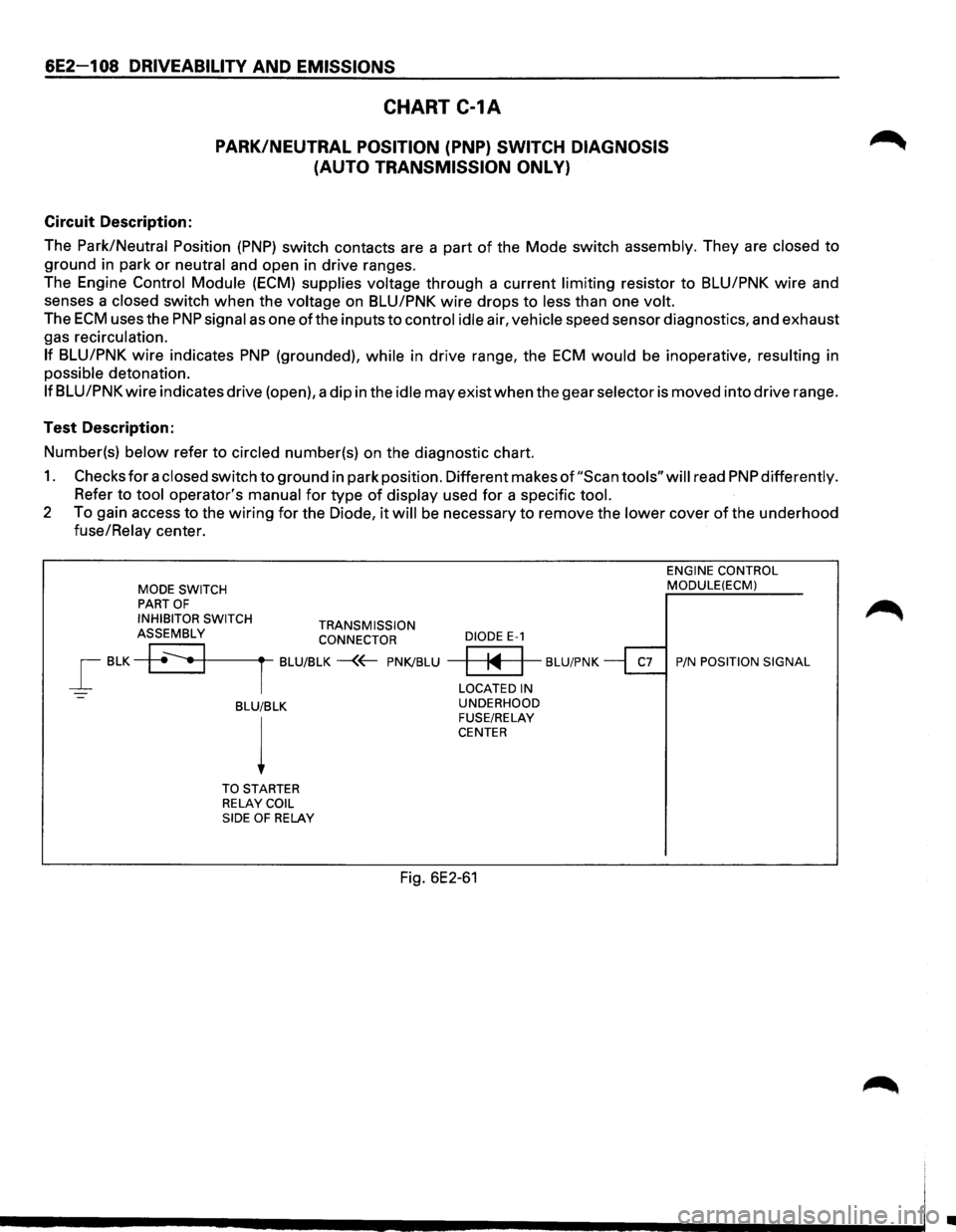
Circuit Description:
The
Park/Neutral Position (PNP) switch contacts are a part of the Mode switch assembly. They are closed to
ground in park or neutral and open in drive ranges.
The Engine
Control Module (ECM) supplies voltage through a current limiting resistor to BLU/PNK wire and
senses a
closed switch when the voltage on BLU/PNK wire drops to less than one volt.
The ECM uses the PNP signal as one ofthe inputs to control idle air, vehicle speed sensor diagnostics, and exhaust
gas recirculation.
If BLU/PNK wire indicates PNP (grounded), while in drive range, the ECM would be inoperative, resulting in
possible detonation.
If BLU/PNK wire indicates drive (open), a dip in the idle may exist when the gear selector is moved into drive range.
Test Description:
Number(s)
below refer to circled number(s) on the diagnostic chart.
1. Checks for a closed switch to ground in park position. Different makes of "Scan tools" will read PNP differently.
Refer to tool operator's manual for type of display used for a specific tool.
2 To gain access to the wiring for the Diode, it will be necessary to remove the lower cover of the underhood
fuse/Relay center.
MODE SWITCH PART OF
INHIBITOR SWITCH TRANSMISSION ASSEMBLY CONNECTOR
_[ BLK +~•+1-------rt--BLU/BLK -{~ PNK/BLU
-BLU/BLK
l
TO STARTER
RELAY COIL
SIDE OF RELAY
DIODE E-1
ENGINE CONTROL MODULE(ECM)
~ BLU/PNK ~ P/N POSITION SIGNAL
LOCATED IN
UNDERHOOD
FUSE/RELAY
CENTER
Fig. 6E2-61
Ill
Page 821 of 1928
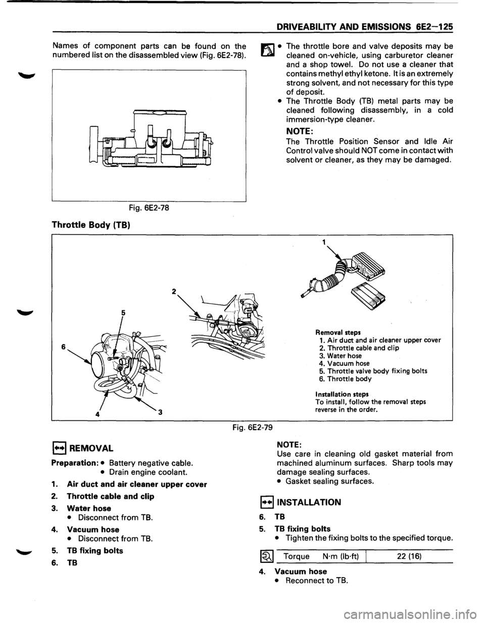
Names of component parts can be found on the
numbered
list on the disassembled view (Fig. 6E2-78).
Fig. 6E2-78
Throttle Body (TB)
5
6
2
DRIVEABILITY AND EMISSIONS 6E2-125
m • The throttle bore and valve deposits may be
t..a.l cleaned on-vehicle, using carburetor cleaner
and a shop towel. Do not use a cleaner that
contains
methyl ethyl ketone. It is an extremely
strong solvent, and
not necessary for this type
of deposit.
• The Throttle Body (TB) metal parts may be
cleaned following disassembly, in a cold
immersion-type cleaner.
NOTE:
The Throttle Position Sensor and Idle Air
Control
valve should NOT come in contact with
solvent or
cleaner, as they may be damaged.
1
Removal steps
1. Air duct and air cleaner upper cover
2.
Throttle cable and clip
3. Water hose
4. Vacuum hose
5.
Throttle valve body fixing bolts
6. Throttle body
Installation steps
To install, follow the removal steps
reverse in
the order.
Fig. 6E2-79
1••1 REMOVAL
Preparation: • Battery negative cable.
•
Drain engine coolant.
1. Air duct and air cleaner upper cover
2. Throttle cable and clip
3. Water hose
• Disconnect from TB.
4. Vacuum hose
• Disconnect from TB.
5. TB fixing bolts
6. TB
NOTE:
Use care in cleaning old gasket material from
machined
aluminum surfaces. Sharp tools may
damage
sealing surfaces.
• Gasket sealing surfaces.
I••IINSTALLATION
6. TB
5. TB fixing bolts
• Tighten the fixing bolts to the specified torque.
~~~ Torque N·m (lb·ft) 22 (16)
4. Vacuum hose
• Reconnect to TB.
Page 864 of 1928
6F-2 ENGINE EXHAUST (V6 3.2L)
When inspecting or replacing exhaust system
components, make sure there is adequate
clearance
from all points on the underbody to prevent over
heating the
floor pan and possible damage to the
passenger
compartment insulation and trim materials.
Check complete exhaust system and nearby body
areas and rear compartment lid for broken, damaged,
missing
or mispositioned parts, open seams, holes,
loose
connections or other deterioration which could
permit exhaust fumes to seep into the rear
compartment or passenger compartment. Dust or
water in the rear compartment may be an indication of
a problem in one of these areas. Any faulty areas
should be corrected immediately.
HANGERS
Various types of hangers are used to support exhaust
system(s). These
include conventional rubber straps,
rubber rings, and rubber
blocks.
The installation of exhaust system supports is very
important,
as improperly installed supports can cause
annoying vibrations
which can be difficult to diagnose.
THREE WAY CATAL VTIC CONVERTER
The three way catalytic converter is an emission
control device added to the exhaust system to reduce
pollutants from the exhaust gas stream.
W CAUTION:
VI • The catalytic converter requires the use of
unleaded fuel only.
Periodic
maintenance of the exhaust system is not
required. If the vehicle is raised for other service, it is
advisable to check the condition of the complete
exhaust system.
A
dual bed monolith catalytic converter is used in
combination
with three way catalytic converter.
Catalytic Types:
Three
way (Reduction/Oxidation) catalyst
The catalyst coating on the three way (reduction)
converter contains
platinum and rhodium which
lowers the levels of oxide of nitrogen (NOx) as well as
hydrocarbons (HC) and carbon monoxide (Co).
GASKET
The gasket must be replaced whenever a new exhaust
pipe,
muffler or catalytic converter is installed.
Page 906 of 1928
7 A-34 AUTOMATIC TRANSMISSION (4L30-E)
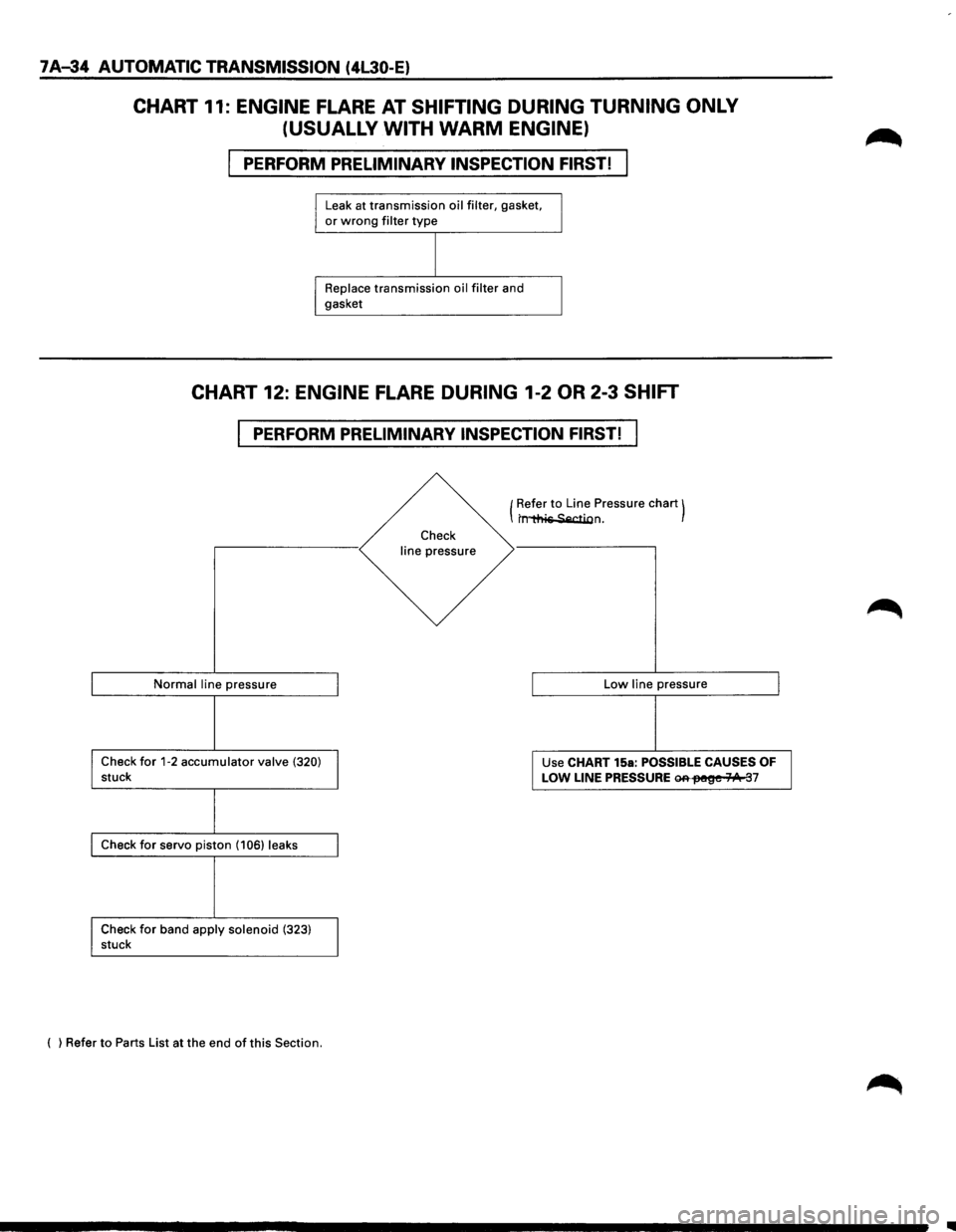
CHART 11: ENGINE FLARE AT SHIFTING DURING TURNING ONLY
(USUALLY WITH
WARM ENGINE)
PERFORM PRELIMINARY INSPECTION FIRST!
Leak at transmission oil filter, gasket, or wrong filter type
Replace transmission oil filter and
gasket
CHART 12: ENGINE FLARE DURING 1-2 OR 2-3 SHIFT
PERFORM PRELIMINARY INSPECTION FIRST!
Normal line pressure
Check for 1-2 accumulator valve (320) stuck
Check for servo piston (106) leaks
Check
for band apply solenoid (323) stuck
( ) Refer
to Parts List at the end of this Section.
Check
line pressure (
Refer
to Line
Pressure chart) t~n.
Low line pressure
Use CHART 15a:
POSSIBLE CAUSES OF
LOW LINE PRESSURE ~fM!~e 71/1t 37
..
Page 1106 of 1928
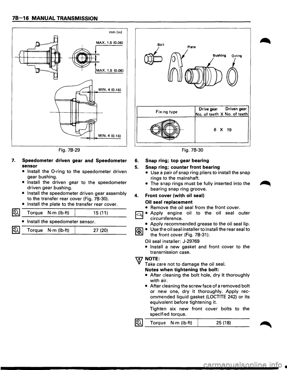
78-16 MANUAL TRANSMISSION
7.
mm{in)
MAX. 1.5 (0.06)
MAX. 1.5 10.06)
MIN. 4 (0.16)
MIN. 4 (0.16)
Fig. 78-29
Speedometer driven gear and Speedometer
sensor
• Install the 0-ring to the speedometer driven
gear bushing.
• Install the driven gear to the speedometer
driven gear bushing.
• Install the speedometer driven gear assembly
to the transfer rear cover (Fig. 78-30).
• Install the plate to the transfer rear cover.
l"i't I Torque N·m (lb·ft) ~ _...:.____---~... ___ _ 15 (11)
• Install the speedometer sensor.
I~I_T_o_rq...;_u_e_N_·_m_(_lb_·ft_l----~. ___ 2_7_(2_0_) __ _
Plate Bolt
~
Fix1ing type Drive gear Driven gear
No. of teeth
X No. of teeth
6 X 19
Fig. 78-30
6. Snap ring; top gear bearing
5. Snap ring; counter front bearing
• Use a pair of snap ring pliers to install the snap
rings to the mainshaft.
• The snap rings must be fully inserted into the
bearing snap ring groove.
4. Front cover (with oil seal)
Oil seal
replacement
• Remove the oil seal from the front cover.
c:::;J • Apply engine oil to the oil seal outer
D circumference.
• Apply recommended grease to the oil seal lip.
1®.1• Use the oil seal installer to install the rear seal to
the
front cover (Fig. 78-31 ).
Oil seal installer: J-29769
• Install a new gasket and front cover to the
transmission case.
'\f7 NOTE:
"+({ Take care not to damage the oil seal.
Notes when tightening the bolt:
• After Gleaning the bolt hole, dry it thoroughly
with air.
• After Gleaning the screw face of a removed bolt
or new one, dry it thoroughly. Apply rec
omme~nded liquid gasket (LOCTITE 242) or its
equivalent before tightening it.
Tighten six
new front cover bolts to the
specified torque.
1~1 Torque N·m (lb·ft) 25 (18)
..