check transmission fluid ISUZU TROOPER 1995 Workshop Manual
[x] Cancel search | Manufacturer: ISUZU, Model Year: 1995, Model line: TROOPER, Model: ISUZU TROOPER 1995Pages: 1928
Page 19 of 1928
(
(
(
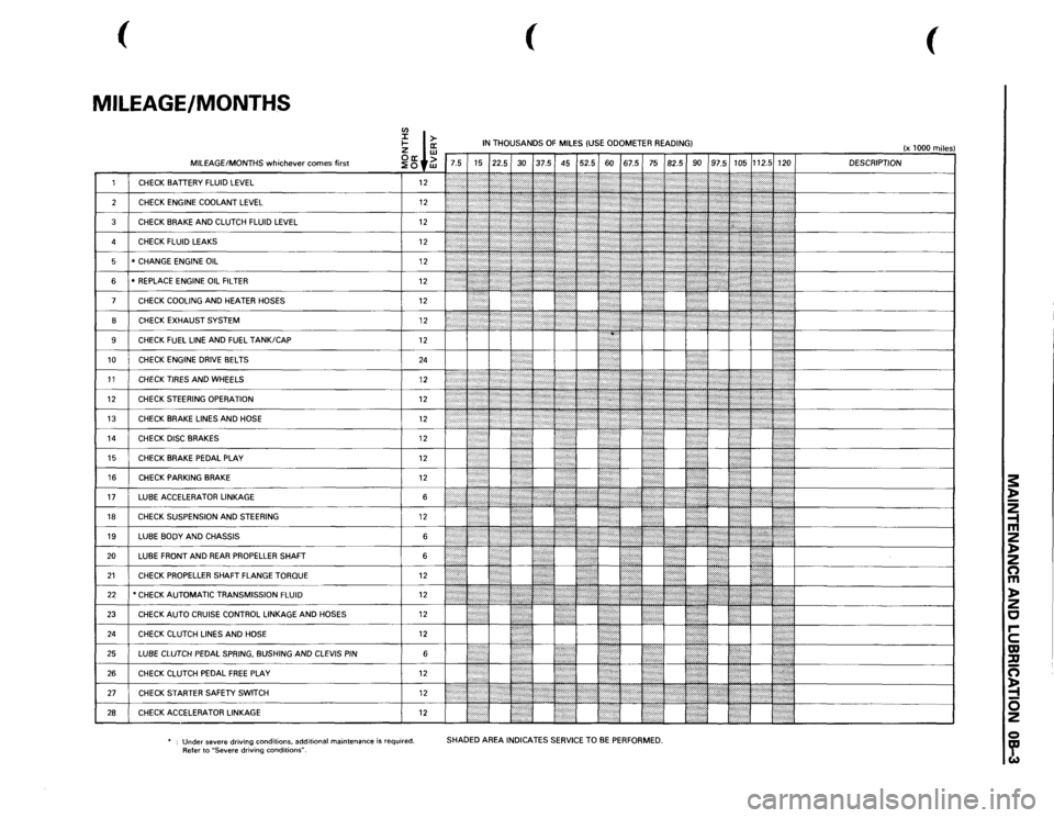
MILEAGE/MONTHS
rn
I ffi
IN THOUSANDS
OF
MILES
(USE
ODOMETER READING)
(x 1000
miles)
~ +~
7.5 15 22.5
30
37.5 45 52.5
60
67.5
75
82.5
90
97.5
105
112.5
120 DESCRIPTION
1
CHECK
BATTERY
FLUID
LEVEL
12
2'-'.:j:
:':
';;;;;
I '' ''
,,,,,,,,,:
[}
2
CHECK
ENGINE
COOLANT
LEVEL
12
':iti:·:
(''''/''?
'';?
,,,,,,,;.;.,.,....
,,,~~
3
CHECK
BRAKE
AND
CLUTCH
FLUID
LEVEL
12
:;:;:;:;:·:·:·.
\::':\' '\"':(\':'''''''''
:'·'·'·:·.,.,,,,
d~~~~~~-------------~
)''
'"''''{''''
'}';;o;o;;
l':':':·:o·.·o·····
4
CHECK
FLUID
LEAKS
12
•.•••..••• ,,......
,,,,,,,,,,,
5
* CHANGE
ENGINE
OIL
12
:.•••:•····
f ) : •
: ; ' {
1:':''''
6
*REPLACE
ENGINE
OIL
FILTER
12
{\::::::::;
[:(o:'.
7
CHECK
COOLING
AND
HEATER
HOSES
12
I : ' :
?
,,,.,,,,,.,:,
.. ;
! • !
•••••••••.
8
CHECK
EXHAUST
SYSTEM
12
I
~
J
:
: ••;·,·····,:·:';';·
•••::::::::::·:;.;
I ;J
., ..... .
9
CHECK
FUEL
LINE
AND
FUEL
TANK/CAP
12
10
CHECK
ENGINE
DRIVE
BELTS
24
. .
I
I
11
CHECKTIRESANDWHEELS
12
li
1:;:~:
}::,
..... ::::, .. ,::,:,:,:,·····
j
12
CHECK
STEERING
OPERATION
12
1
r ., .. ,,.,,.
·
I
13
CHECK
BRAKE
LINES
AND
HOSE
12
~
~
<
.,>
/ ':'??i'
}
J
t
''}{
14
CHECK
DISC
BRAKES
12
10
}}
UL
'I I
•....
15
CHECK
BRAKE
PEDAL
PLAY
12
I"
.. )t
16
CHECK
PARKING
BRAKE
12
li
I
17
LUBE
ACCELERATOR
LINKAGE
6
,,.:
....
I
18
CHECK
SUSPENSION
AND
STEERING
12
••·•••·•··•
19
LUBE
BODY
AND
CHASSIS
6
1''''':'''''''''''
20
LUBE
FRONT
AND
REAR
PROPELLER
SHAFT 6
{:
!: • :•••••l
21
CHECK
PROPELLER
SHAFT FLANGE
TORQUE
12
•
22
*CHECK AUTOMATIC TRANSMISSION
FLUID
12
... ,, ,....
@{I{
,,,,,,,,
ttJ
·~+---------------!
23
CHECK
AUTO
CRUISE
CONTROL
LINKAGE
AND
HOSES
12
~ .
:l
!•••:
24
CHECK
CLUTCH
LINES
AND
HOSE
12
25
LUBE
CLUTCH
PEDAL
SPRING,
BUSHING
AND
CLEVIS
PIN
6
l':":"·:"ii
26
CHECK
CLUTCH
PEDAL
FREE
PLAY
12
1/JJ(
21
cHEcK sTARTER SAFETY swiTCH 12
1/,,,,.,,,,,,,,,
,,,,,,,,,
-~~~--~~~~~~-~~~~~[============J
28
CHECK
ACCELERATOR
LINKAGE
12
m ::::::::]
!•'····
'.!
Under
severe driving conditions,
additional
maintenance
is required.
Refer to
"Severe
driving
conditions".
SHADED AREA
INDICATES
SERVICE
TO
BE PERFORMED.
s: ~ 2 -1 m 2 )> 2 n m )> 2 c rc m ::u n ~ 0 2 Q ~
Page 20 of 1928
OB-4 MAINTENANCE AND LUBRICATION
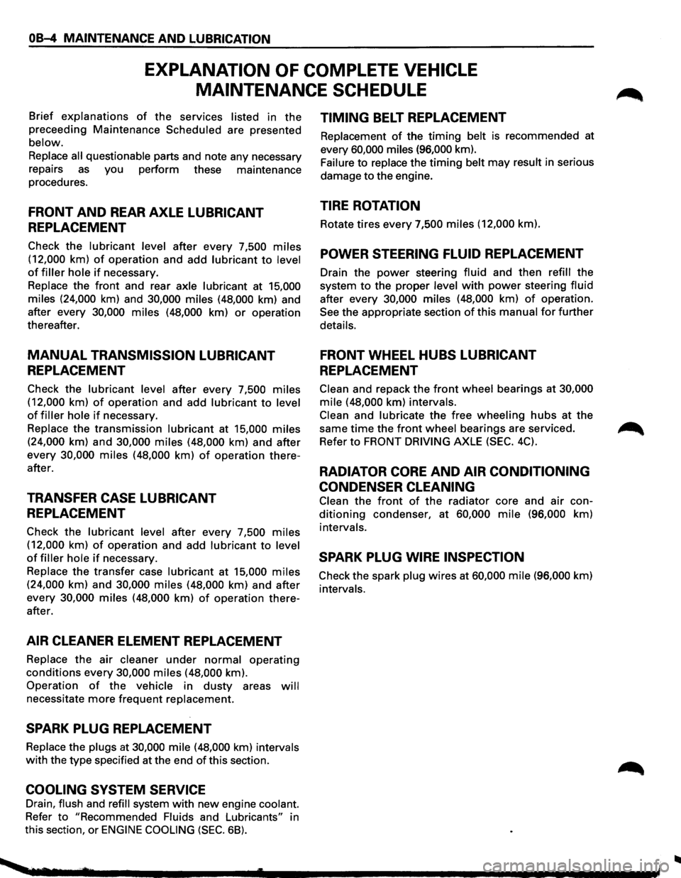
EXPLANATION OF COMPLETE VEHICLE
MAINTENANCE
SCHEDULE
Brief explanations of the services listed in the
preceeding Maintenance Scheduled are presented
below.
Replace
all questionable parts and note any necessary
repairs
as you perform these maintenance
procedures.
FRONT AND REAR AXLE LUBRICANT
REPLACEMENT
Check the lubricant level after every 7,500 miles
(12,000 km) of operation and add lubricant to level
of filler hole if necessary.
Replace the front and rear
axle lubricant at 15,000
miles (24,000 km) and 30,000 miles (48,000 km) and
after every 30,000
miles (48,000 km) or operation
thereafter.
MANUAL TRANSMISSION LUBRICANT
REPLACEMENT
Check the lubricant level after every 7,500 miles
(12,000 km) of operation and add lubricant to level
of filler hole if necessary.
Replace the transmission
lubricant at 15,000 miles
(24,000 km) and 30,000 miles (48,000 km) and after
every 30,000
miles (48,000 km) of operation there
after.
TRANSFER CASE LUBRICANT
REPLACEMENT
Check the lubricant level after every 7,500 miles
(12,000 km) of operation and add lubricant to level
of filler hole if necessary.
Replace
the transfer case lubricant at 15,000 miles
(24,000 km) and 30,000 miles (48,000 km) and after
every 30,000
miles (48,000 km) of operation there
after.
AIR CLEANER ELEMENT REPLACEMENT
Replace the air cleaner under normal operating
conditions every 30,000 miles (48,000 km).
Operation
of the vehicle in dusty areas will
necessitate more frequent replacement.
SPARK PLUG REPLACEMENT
Replace the plugs at 30,000 mile (48,000 km) intervals
with the type specified at the end of this section.
COOLING SYSTEM SERVICE
Drain, flush and refill system with new engine coolant.
Refer
to "Recommended Fluids and Lubricants" in
this section,
or ENGINE COOLING (SEC. 68).
TIMING BELT REPLACEMENT
Replacement of the timing belt is recommended at
every 60,000 miles (96,000 km).
Failure
to replace the timing belt may result in serious
damage
to the engine.
TIRE ROTATION
Rotate tires every 7,500 miles (12,000 km).
POWER STEERING FLUID REPLACEMENT
Drain the power steering fluid and then refill the
system
to the proper level with power steering fluid
after every 30,000 miles (48,000 km) of operation.
See the appropriate section
of this manual for further
details.
FRONT WHEEL HUBS LUBRICANT
REPLACEMENT
Clean and repack the front wheel bearings at 30,000
mile (48,000 km) intervals.
Clean and lubricate the free wheeling hubs at the
same
time the front wheel bearings are serviced.
Refer
to FRONT DRIVING AXLE (SEC. 4C).
RADIATOR CORE AND AIR CONDITIONING
CONDENSER CLEANING
Clean the front of the radiator core and air con
ditioning condenser, at 60,000 mile (96,000 km)
intervals.
SPARK PLUG WIRE INSPECTION
Check the spark plug wires at 60,000 mile (96,000 km)
intervals.
..
Page 22 of 1928
OB-6 MAINTENANCE AND LUBRICATION
BRAKE SYSTEMS OPERATION
Watch for the "BRAKE" light coming on. Other
signs of possible brake trouble are such things as
repeated pulling to one side when braking, unusual
sounds
when braking or between brake
applications,
or increased brake pedal travel. If you
note one of these conditions, repair the system at
once.
For convenience, the
following should be done
when wheels are removed for rotation: Inspect lines
and hoses
for proper hookup, bindings, leaks, crack,
chafing etc.
Inspect disc brake pads for wear and
rotors
for surface condition.
Inspect other brake parts, including parking brake
drums, linings etc., at the same time. Check parking
brake adjustment.
Inspect brakes more often if habit or
conditions
result in frequent braking.
PARKING BRAKE AND TRANSMISSION
PARK MECHANISM OPERATION
Park on a fairly steep hill and hold the vehicle with
the parking brake only. This checks holding ability.
On
automatic transmission vehicles, shifting from
"P" position to the other positions cannot be made
unless
the brake pedal is depressed when the key
switch is in
"ON" position or the engine running.
WARNING
•
Before checking starter safety switch
operation below,
be sure to have enough
room around the
vehicle. Then firmly apply
both the parking brake and the regular brake.
Do not
use the accelerator pedal. If the engine
starts, be ready
to turn off the key promptly.
Take these precautions because the vehicle
could move
without warning and possibly
cause personal injury
or property damage.
STARTER SAFETY SWITCH OPERATION
(AUTOMATIC TRANSMISSION)
Check by trying to start the engine in each gear
while setting the parking brake and the foot brake.
The starter
should crank only in "P" (Park) or "N"
(Neutral).
STARTER SAFETY SWITCH OPERATION
(MANUAL TRANSMISSION)
To check, place the shift lever in "Neutral", push
the clutch pedal halfway and try to start. The starter
should not crank. The starter should crank only
when the clutch pedal is fully depressed.
ACCELERATOR LINKAGE LUBRICATION
Lubricate the accelerator pedal fulcrum pin with
chassis grease.
STEERING AND SUSPENSION
INSPECTION
Inspect front and rear suspension and steering
system
for damaged, loose or missing parts or signs
of wear. Inspect power steering lines and hoses for
proper hookup, binding, leaks, cracks, chafing, etc.
BODY AND CHASSIS LUBRICATION
Lubricate the key lock cylinders, the hood latch, the
hood and door hinges, the door check link, the
parking cable guides,
the underbody contact points,
and the linkage.
PROPELLER SHAFT INSPECTION AND
LUBRICATION
Lubricate sliding yoke and universal joints with
grease containing MOS2 (disulfide molybdenum
type grease) at the interval shown in the
Maintenance Schedule. Check for play in normal
direction of rotation of sliding yoke and universal
joints. Also check
propeller shaft flange-to-pinion
bolts for proper torque of 63 N·m (46 lb·ft) for front
and rear propeller shaft.
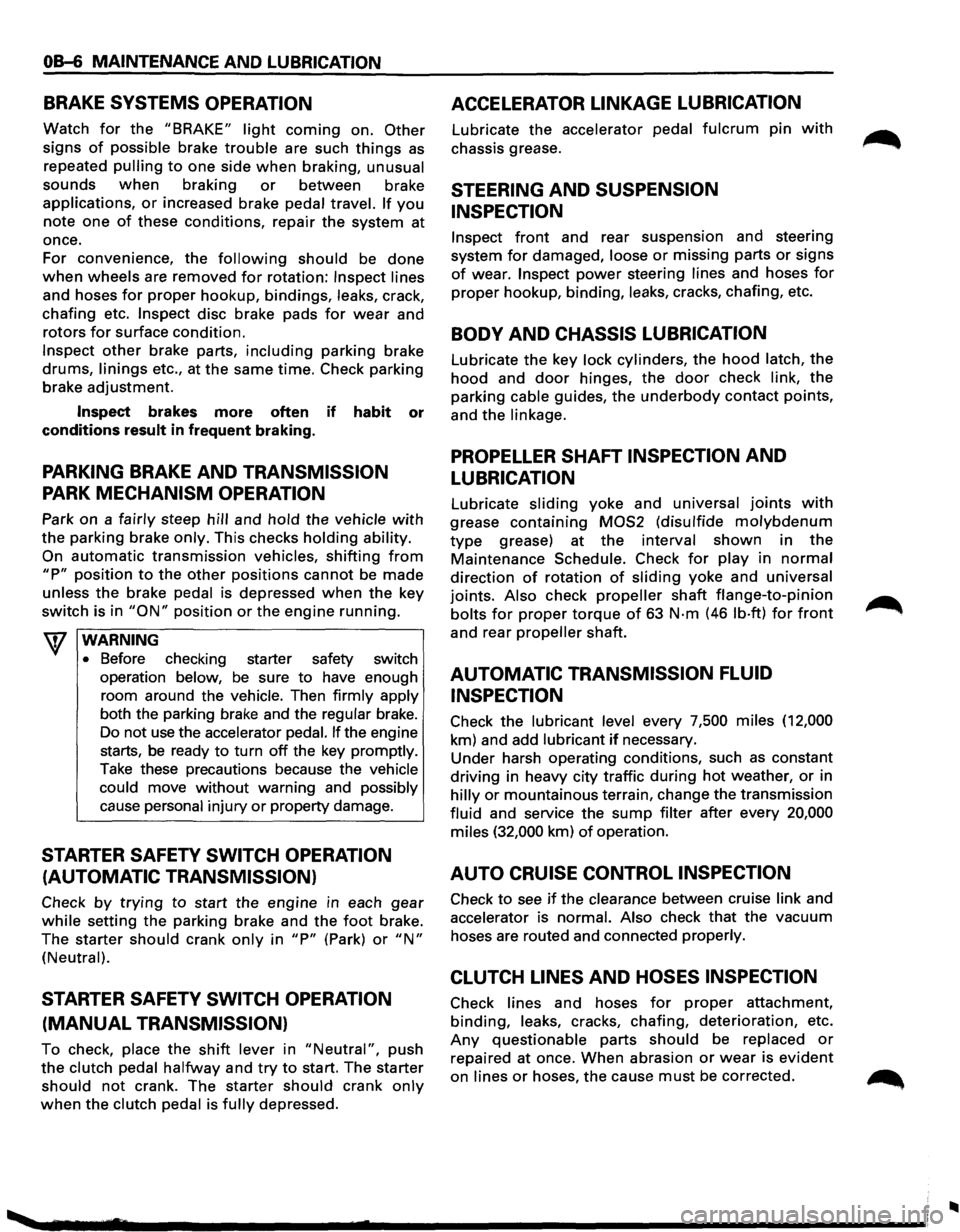
AUTOMATIC TRANSMISSION FLUID
INSPECTION
Check the lubricant level every 7,500 miles (12,000
km) and add lubricant
if necessary.
Under harsh operating conditions, such as constant
driving in heavy city traffic during
hot weather, or in
hilly or mountainous terrain, change the transmission
fluid and service the
sump filter after every 20,000
miles (32,000 km) of operation.
AUTO CRUISE CONTROL INSPECTION
Check to see if the clearance between cruise link and
accelerator is normal. Also check that the vacuum
hoses are routed and connected properly.
CLUTCH LINES AND HOSES INSPECTION
Check lines and hoses for proper attachment,
binding, leaks, cracks, chafing, deterioration, etc.
Any questionable parts should be replaced or
repaired at once. When abrasion or wear is evident
on lines or hoses, the cause must be corrected.
..
Page 322 of 1928
SA-2 HYDRAULIC BRAKES
BRAKE SYSTEM DIAGNOSIS
ROAD TESTING THE BRAKES
Brake Test
Brakes should be tested on a dry, clean, reasonably
smooth and
level roadway. A true test of brake
performance cannot be made
if the roadway is
wet, greasy
or covered with loose dirt so that all
tires do not grip the road equally. Testing will also
be adversely affected if the roadway is crowned so
as to throw the weight of the vehicle toward
wheels on one side or if the roadway is so rough
that wheels tend to bounce. Test the brakes at dif
ferent vehicle speeds with both light and heavy
pedal pressure; however, avoid locking the wheels
and sliding the tires. Locked wheels and sliding
tires do not indicate brake efficiency, since heavily
braked but turning wheels will stop the vehicle in
less distance than locked wheels. More tire-to-road
friction is present
with a heavily braked turning tire
then
with a sliding tire.
The standard brake system is designed and
balanced
to avoid locking the wheels except at very high
deceleration
levels.
It
is designed this way because the shortest stopping
distance and best
control is achieved without brake
lock-up.
Because of high deceleration capability, a firmer pedal
may be felt at higher deceleration levels.
External Conditions That Affect Brake
Performance
1.
2.
3.
Tires: Tires having unequal contact and grip on
the road
will cause unequal braking. Tires must
be equally inflated, identical in size, and the tread
pattern
of right and left tires must be approxi
mately equal.
Vehicle loading:
A heavily loaded vehicle requires
more braking effort.
Wheel Alignment: Misalignment of the wheels,
particularly
in regard to excessive camber and
caster,
will cause the brakes to pull to one side.
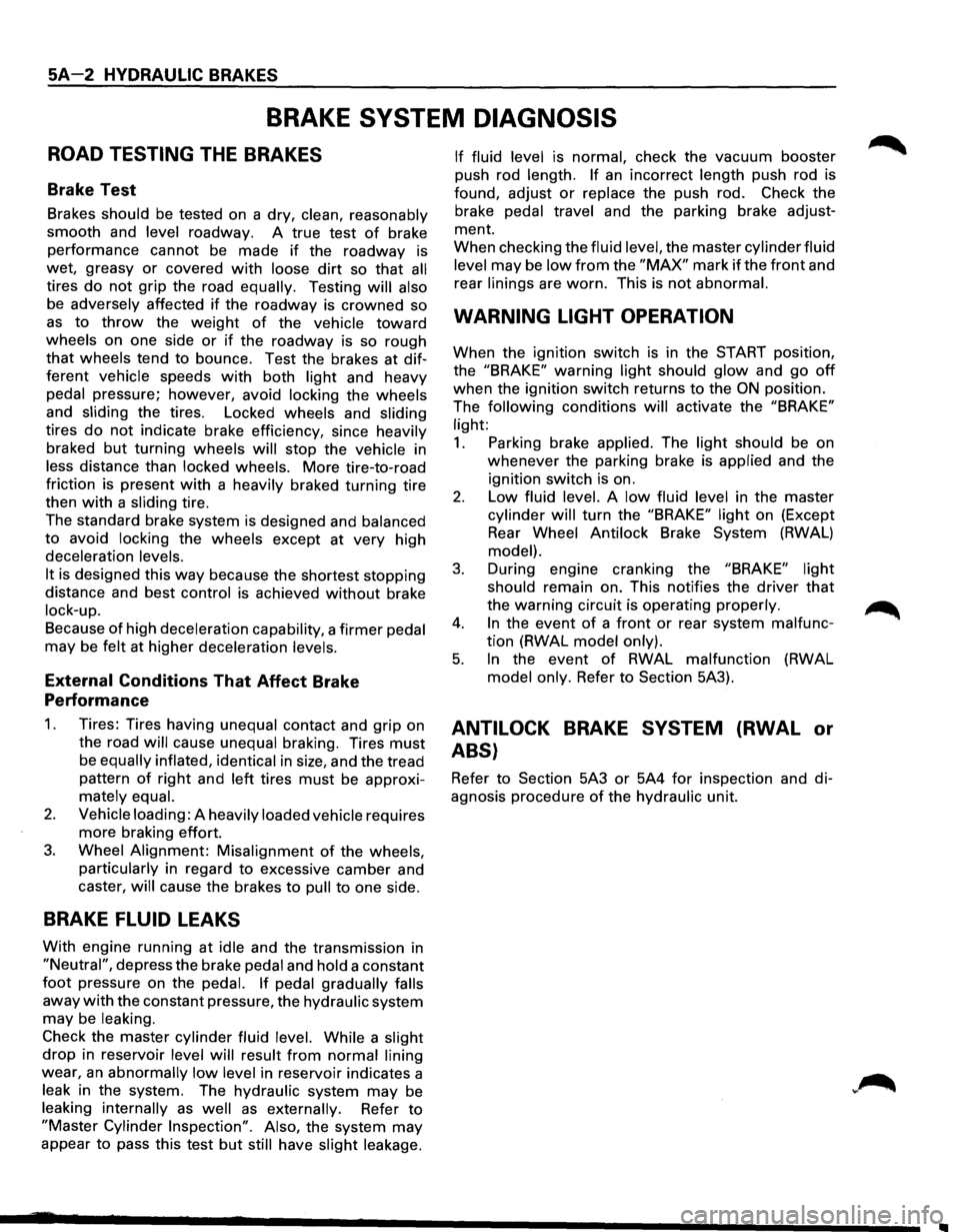
BRAKE FLUID LEAKS
With engine running at idle and the transmission in
"Neutral", depress the brake pedal and hold a constant
foot pressure on the pedal. If pedal gradually falls
away with the constant pressure, the hydraulic system
may be leaking.
Check the master cylinder fluid level. While a slight
drop in reservoir level will result from normal lining
wear, an abnormally low level in reservoir indicates a
leak in the system. The hydraulic system may be
leaking internally as well as externally. Refer to
"Master Cylinder Inspection". Also, the system may
appear
to pass this test but still have slight leakage. If
fluid level
is normal, check the vacuum booster
push rod
length. If an incorrect length push rod is
found, adjust
or replace the push rod. Check the
brake
pedal travel and the parking brake adjust
ment.
When checking the
fluid level, the master cylinder fluid
level
may be low from the "MAX" mark if the front and
rear
linings are worn. This is not abnormal.
WARNING LIGHT OPERATION
When the ignition switch is in the START position,
the
"BRAKE" warning light should glow and go off
when the ignition switch returns to the ON position.
The
following conditions will activate the "BRAKE"
light:
1. Parking brake applied. The light should be on
whenever the parking brake is applied and the
ignition switch is on.
2. Low fluid level. A low fluid level in the master
cylinder will turn the "BRAKE" light on (Except
Rear
Wheel Antilock Brake System (RWAL)
model).
3. During engine cranking the "BRAKE" light
should
remain on. This notifies the driver that
the warning circuit is operating properly.
4. In the event of a front or rear system malfunc
tion (RWAL model only).
5. In the event of RWAL malfunction (RWAL
model only. Refer to Section 5A3).
ANTILOCK BRAKE SYSTEM (RWAL or
ABS}
Refer to Section 5A3 or 5A4 for inspection and di
agnosis procedure of the hydraulic unit.
..
Page 632 of 1928
68 - 4 ENGINE COOLING
ON-VEHICLE SERVICE
DRAINING AND REFILLING COOLING
SYSTEM
Before draining the cooling system, inspect the sys
tem and perform any necessary service to ensure that
it is clean, does not leak and is in proper working
order. The Engine Coolant (EC) level should be be
tween the "MIN" and "MAX" lines of reserve tank
when the engine is cold. If low, check for leakage and
add
EC up to the "MAX" line. There should not be any
excessive deposit of rust or scales around the radiator
cap
or radiator filler hole, and the EC should also be
free
from oil. Replace the EC if excessively dirty.
1. Completely drain the cooling system by opening
the drain petcock at the bottom of the radiator.
2. Remove the radiator cap.
W WARNING
To avoid the danger of being burned, do not
remove the cap while the engine and radiator
are still hot. Scalding fluid and steam can be
blown out under pressure.
3. Disconnect all hoses from the EC reserve tank.
Scrub and clean the inside of the reserve tank with
soap and water. Flush it well with clean water,
then drain it. Install the reserve tank and hoses.
WATER PUMP
3
j
2
4. Refill the cooling system with the EC using a
solution that is at least 50 percent antifreeze but no
more than 70 percent antifreeze.
5. Fill the radiator to the base of the filler neck.
Fill the EC reserve tank to "MAX" line when the
engine is cold.
6. Block the drive wheels and firmly apply the park
ing brake.
Shift an automatic transmission to "P"
(Park) or a manual transmission to neutral.
7. Remove the radiator cap. Start the engine and
warm it up at 2,500 -3,000 rpm for about 30
minutes.
8. When the air comes out from the radiator filler
neck and the EC level has gone down, replenish
with the EC. Repeat this procedure until the EC
level does not go down. Then stop the engine and
install the radiator cap. Let the engine cool down.
9. After the engine has cooled, replenish with EC up
to the "MAX" line of the reserve tank.
10. Start the engine. With the engine running at 3,000
rpm, make sure there is no running water sound
from the heater core (behind the center console).
11. If the running water sound is heard, repeat steps 7
to 10.
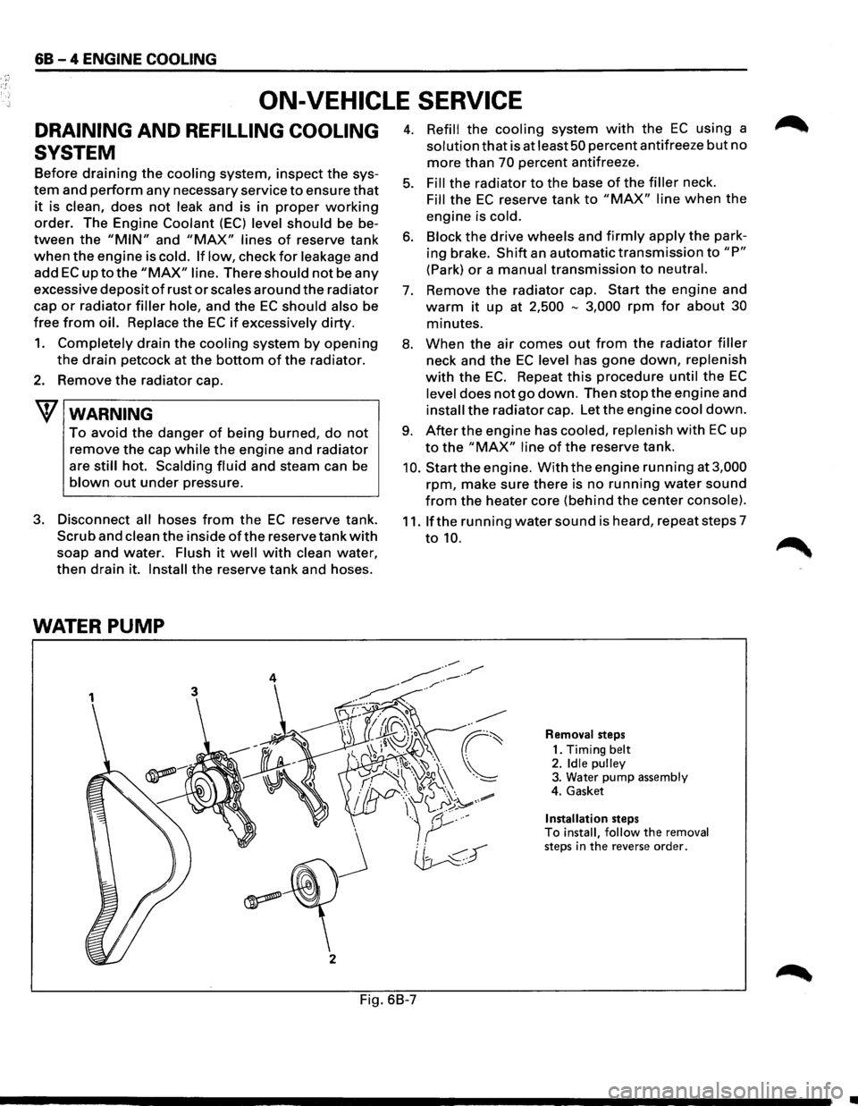
Removal steps
1. Timing
belt 2. Idle pulley 3. Water pump assembly
4. Gasket
Installation steps To install, follow the removal steps in the reverse order.
Fig. 6B-7
•
Page 873 of 1928
AUTOMATIC TRANSMISSION (4l30-E) 7 A-1
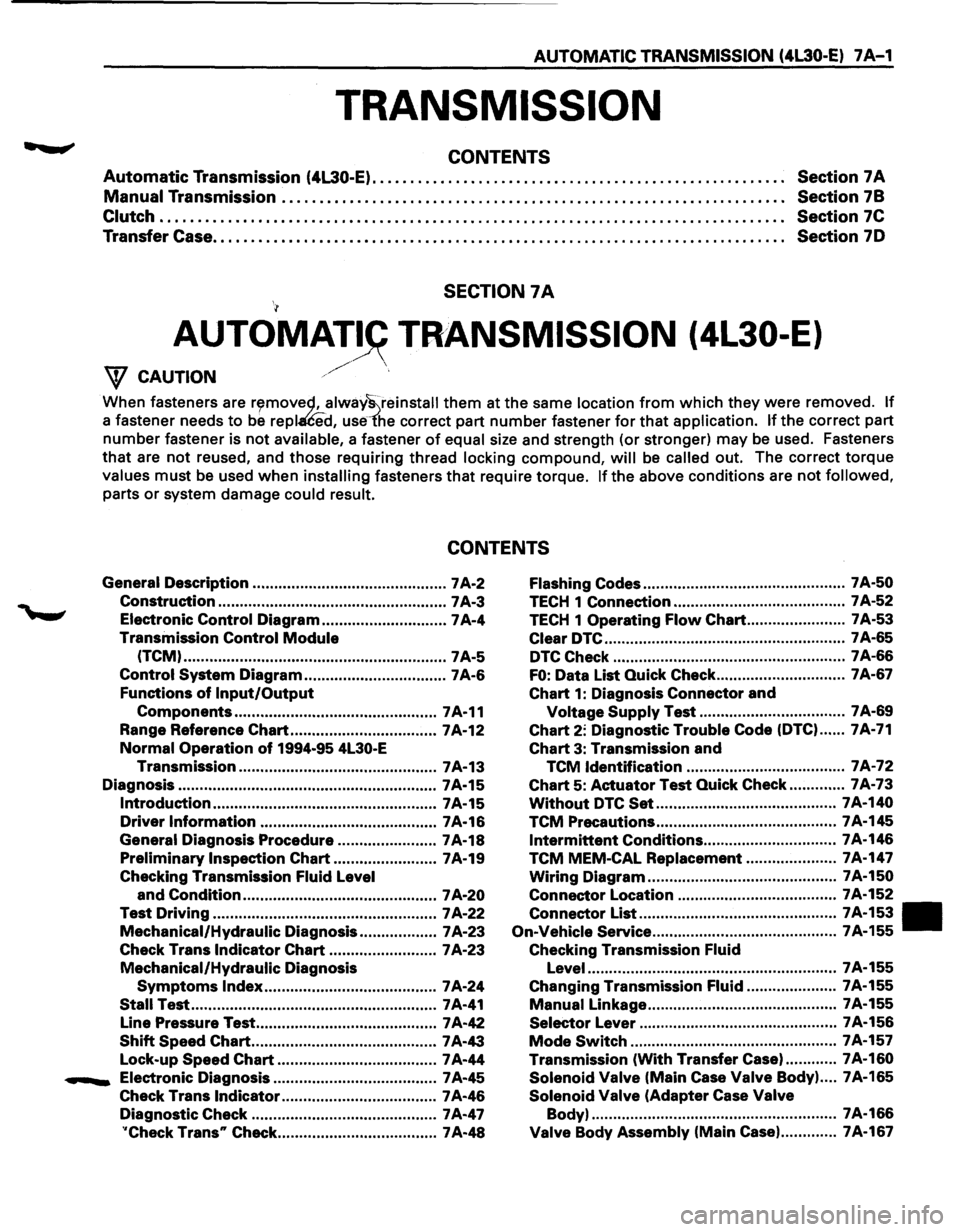
TRANSMISSION
CONTENTS
Automatic Transmission (4L30-E). . . . . . . . . . . . . . . . . . . . . . . . . . . . . . . . . . . . . . . . . . . . . . . . . . . . . . . Section 7 A
Manual Transmission . .
. . . . . . . . . . . . . . . . . . . . . . . . . . . . . . . . . . . . . . . . . . . . . . . . . . . . . . . . . . . . . . . . . Section
78
Clutch . . . . . . . . . . . . . . . . . . . . . . . . . . . . . . . . . . . . . . . . . . . . . . . . . . . . . . . . . . . . . . . . . . . . . . . . . . . . . . . . . . . Section 7C
Transfer Case. . . . . . . . . . . . . . . . . . . . . . . . . . . . . . . . . . . . . . . . . . . . . . . . . . . . . . . . . . . . . . . . . . . . . . . . . . . . Section 70
SECTION 7A
AUTOMAT~ TRANSMISSION (4L30-E)
/' W CAUTION ./
When fasteners are r~movec;l, alway~reinstall them at the same location from which they were removed. If
a fastener needs to be repl£ed, use1'he correct part number fastener for that application. If the correct part
number fastener is not available, a fastener of equal size and strength (or stronger) may be used. Fasteners
that are not reused, and those requiring thread locking compound, will be called out. The correct torque
values must be used when installing fasteners that require torque. If the above conditions are not followed,
parts or system damage could result.
CONTENTS
General Description ............................................. 7 A-2 Flashing Codes ............................................... 7 A-50
Construction ..................................................... 7 A-3 TECH 1 Connection ........................................ 7 A-52
Electronic Control Diagram ............................. 7A-4 TECH 1 Operating Flow Chart ....................... 7 A-53
Transmission
Control Module Clear DTC ........................................................ 7 A-65
(TCM) ............................................................. 7A-5 DTC Check ...................................................... 7 A-66
Control System Diagram ................................. 7 A-6 FO: Data List Quick Check .............................. 7A-67
Functions
of Input/Output Chart 1: Diagnosis Connector and
Components ............................................... 7A-11 Voltage Supply Test .................................. 7A-69
Range Reference
Chart .................................. 7A-12 Chart 2: Diagnostic Trouble Code (DTC) ...... 7A-71
Normal Operation of 1994-95 4L30-E Chart 3: Transmission and
Transmission .............................................. 7 A-13
TCM Identification ..................................... 7 A-72
Diagnosis ............................................................ 7A-15
Chart 5: Actuator Test Quick Check ............. 7A-73
Introduction .................................................... 7A-15 Without DTC Set .......................................... 7 A-140
Driver Information ......................................... 7 A-16 TCM Precautions .......................................... 7A-145
General Diagnosis Procedure ....................... 7A-18 Intermittent Conditions ............................... 7A-146
Preliminary Inspection Chart ........................ 7 A-19 TCM MEM-CAL Replacement ..................... 7A-147
Checking Transmission Fluid Level Wiring Diagram ............................................ 7A-150
and
Condition ............................................. 7 A-20 Connector Location
..................................... 7A-152
Test Driving .................................................... 7 A-22
Mechanical/Hydraulic Diagnosis .................. 7 A-23
Connector List .............................................. 7A-153 •
On-Vehicle
Service ........................................... 7A-155
Check Trans Indicator Chart ......................... 7 A-23 Checking Transmission Fluid
Mechanical/Hydraulic
Diagnosis Level .......................................................... 7A-155
Symptoms Index ........................................ 7A-24 Changing Transmission Fluid ..................... 7A-155
Stall Test ......................................................... 7 A-41 Manual Linkage ............................................ 7A-155
Line Pressure Test .......................................... 7 A-42
Selector Lever .............................................. 7 A-156
Shift Speed Chart ........................................... 7 A-43 Mode Switch ................................................ 7A-157
Lock-up
Speed Chart ..................................... 7 A-44 Transmission
(With Transfer Case). ........... 7A-160
....._ Electronic Diagnosis ...................................... 7 A-45 Solenoid Valve (Main Case Valve Body) .... 7A-165
Check Trans Indicator .................................... 7 A-46 Solenoid Valve (Adapter Case Valve
Diagnostic Check ........................................... 7 A-47 Body)
......................................................... 7A-166
''Check Trans" Check ..................................... 7 A-48 Valve Body Assembly (Main Case) ............. 7A-167
Page 891 of 1928
AUTOMATIC TRANSMISSION (4l30-E) 7A-19
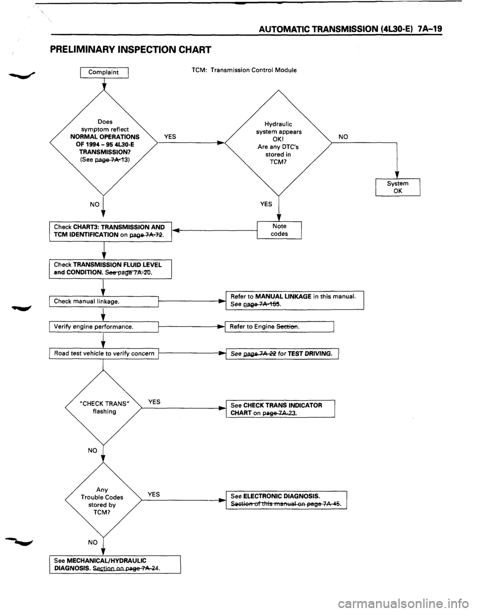
PRELIMINARY INSPECTION CHART
Does symptom reflect
NORMAL OPERATIONS
OF 1994 -95 4L30·E
TRANSMISSION?
(See p.age-1-Ac13)
YES
Check CHART3: TRANSMISSION AND TCM IDENTIFICATION on page-~n.
Check TRANSMISSION FLUID LEVEL and CONDITION. See--page"'7A'•2'0.
Check manual linkage. TCM:
Transmission Control Module
Hydraulic system appears OK!
Are any DTC's stored in TCM?
NO
Refer to MANUAL LINKAGE in this manual.
See~.
Ll_v_e_rify_e_n_g_in_e..:.p_e~rf_or_m_a_n_c_e. ___ l--------1•~1 Refer to Engine Seeticm.
Road
test vehicle to verify concern l----------;..f~s~e;;e-;:ga;;;:;:ge~7.A:o.~2i2f;fo;;r~TiE:SsTTDD~RmlvliiNNiGG~.l
UCHECK TRANS"
flashing >--Y-ES ________ ~ See CHECK TRANS INDICATOR
CHART
on page 7A-23.
Any
Trouble Codes stored by TCM?
YES
See
MECHANICAL/HYDRAULIC DIAGNOSIS.~.
See ELECTRONIC DIAGNOSIS. ~r tliis nusnllal on-JH!ge 7A 45.
Page 892 of 1928
7 A-20 AUTOMATIC TRANSMISSION (4L30-E)
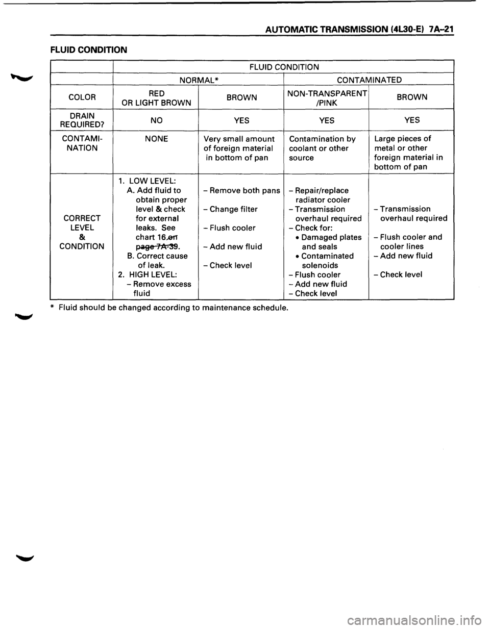
CHECKING TRANSMISSION FLUID
LEVEL AND CONDITION
Checking fluid level and condition (color and odor)
at
regular intervals will provide early diagnosis
information about the transmission. This inform
ation may be used to correct a condition that, if not
detected early, could result in major transmission
repairs.
IMPORTANT: When new, automatic transmission
fluid is red in color. As the vehicle is driven, the
transmission
fluid will begin to look darker in color.
The
color may eventually appear light brown.
A DARK
brown color with burnt odor may indicate
excessive
fluid deterioration and signal a need for
fluid change.
FLUID LEVEL
When adding
or changing fluid, use only DEXRON
®-Ill.
Refer to the Maintenance and Lubrication (Section 0
of this manual) for maintenance information and
servicing
interval.
\f CAUTION: DO NOT OVERFILL
Overfilling will cause foaming, loss ~f fluid,
abnormal shifting and possible damage to
the transmission.
1. Start engine and drive vehicle until normal AfT
oil operating temperature is reached:
NOTE: The automatic transmission fluid level
must be checked with the vehicle at normal
A/T oil operating temperature: 75 TO 85°C
(167 TO 185°F) MEASURED WITH TECH1 SCAN
TOOL.
Temperature will greatly affect transmission
fluid level.
If the vehicle is not at normal AfT oil operating
temperature and the proper checking
procedures are
not followed, the result could
be a false reading of the fluid level indicator
and
an incorrect adjustment of the fluid level.
2. Park vehicle on level ground.
3. Move gear selector to "Park".
4. Apply parking brake and block wheels.
5. Allow vehicle to idle for 3 minutes with all
accessories turned off.
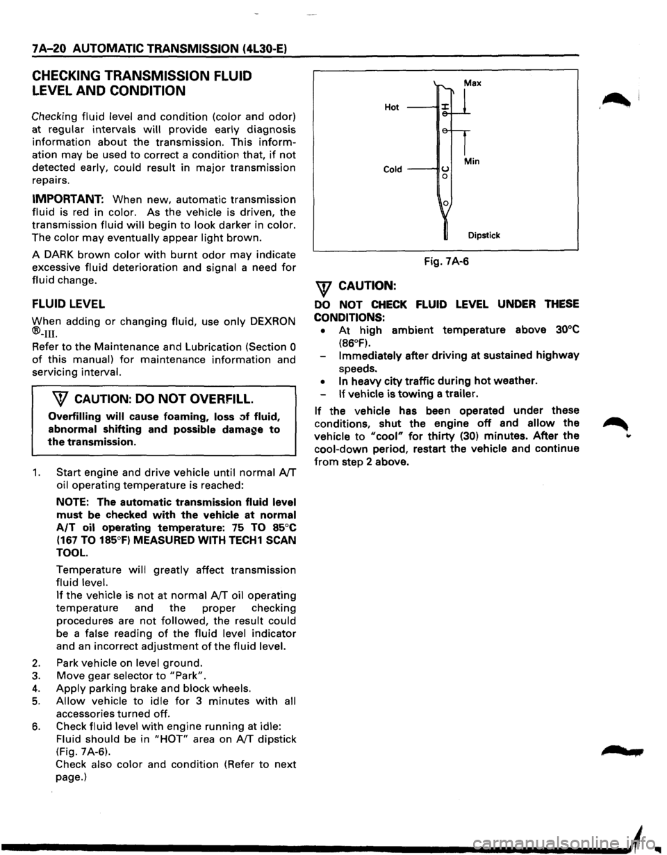
6. Check fluid level with engine running at idle:
Fluid should
be in "HOT" area on AfT dipstick
(Fig. 7A-6).
Check also color and condition (Refer to next
page.)
Hot
Cold ---IIU 0
0
Min
Dipstick
Fig. 7A-6
\f CAUTION:
DO NOT CHECK FLUID LEVEL UNDER THESE
CONDITIONS: •
At high ambient temperature above 30°C
(86°F).
Immediately after driving at sustained highway
speeds.
• In heavy city traffic during hot weather.
If vehicle is towing a trailer.
If the vehicle has been operated under these
conditions,
shut the engine off and allow the
vehicle to "cool" for thirty (30) minutes. After the
cool-down period, restart the vehicle and continue
from step 2 above.
'~I
......
Page 893 of 1928
AUTOMATIC TRANSMISSION (4L30-E) 7A-21
FLUID CONDITION
FLUID CONDITION
NORMAL* CONTAMINATED
COLOR
RED BROWN NON-TRANSPARENT BROWN OR LIGHT BROWN
/PINK
DRAIN NO
YES YES YES
REQUIRED?
CO NT AMI- NONE Very small amount Contamination by Large pieces of
NATION of foreign material coolant or other metal or other
in bottom of pan
source foreign material in
bottom of pan
1. LOW LEVEL:
A. Add fluid to -
Remove both pans -Repair/replace
obtain
proper radiator cooler
level
& check -Change filter -Transmission -Transmission
CORRECT for external overhaul required overhaul required
LEVEL leaks. See -Flush cooler -Check for:
& chart 16..811 • Damaged plates -Flush cooler and
CONDITION ~· -Add new fluid and seals cooler
lines
B. Correct cause • Contaminated -Add new fluid
of leak. -Check level solenoids
2. HIGH LEVEL: -Flush cooler -Check level
-Remove excess -Add new fluid
fluid -Check level
* Fluid should be changed according to maintenance schedule.
Page 911 of 1928
AUTOMATIC TRANSMISSION (4L30-E) 7 A-39
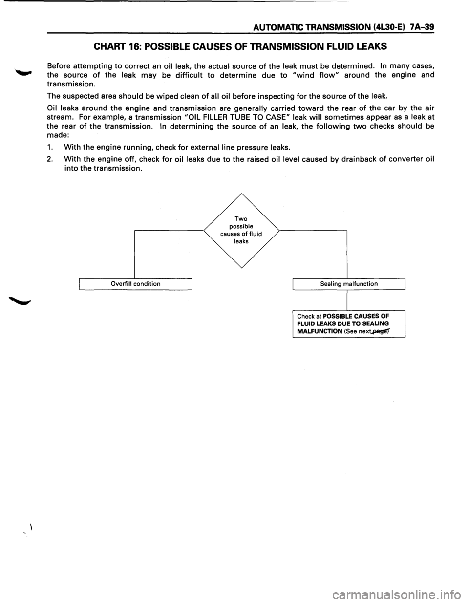
CHART 16: POSSIBLE CAUSES OF TRANSMISSION FLUID LEAKS
Before attempting to correct an oil leak, the actual source of the leak must be determined. In many cases,
the source
of the leak may be difficult to determine due to "wind flow" around the engine and
transmission.
The suspected area
should be wiped clean of all oil before inspecting for the source of the leak.
Oil leaks
around the engine and transmission are generally carried toward the rear of the car by the air
stream. For example, a transmission "OIL FILLER TUBE TO CASE" leak will sometimes appear as a leak at
the rear
of the transmission. In determining the source of an leak, the following two checks should be
made:
1. With the engine running, check for external line pressure leaks.
2. With the engine off, check for oil leaks due to the raised oil level caused by drainback of converter oil
into the transmission.
Overfill condition
Two possible causes of fluid
leaks
Sealing
malfunction
Check at POSSIBLE CAUSES OF FLUID LEAKS DUE TO SEALING
MALFUNCTION (See nex~