height ISUZU TROOPER 1995 User Guide
[x] Cancel search | Manufacturer: ISUZU, Model Year: 1995, Model line: TROOPER, Model: ISUZU TROOPER 1995Pages: 1928
Page 191 of 1928
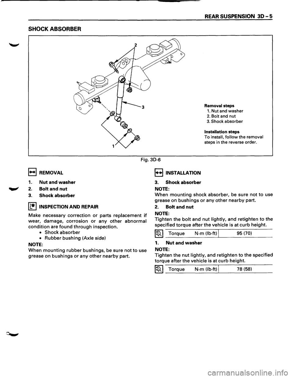
SHOCK ABSORBER
REAR SUSPENSION 30-5
Removal steps
1. Nut and washer
2. Bolt and nut
3. Shock absorber
Installation steps
To
install, follow the removal
steps in the reverse order.
1++1 REMOVAL
1. Nut and washer
2. Bolt and nut
Fig. 30-6
I••IINSTALLATION
3. Shock absorber
NOTE:
3. Shock absorber
IL•IINSPECTION AND REPAIR
Make necessary correction or parts replacement if
wear, damage, corrosion or any other abnormal
condition are found through inspection.
• Shock absorber
• Rubber bushing (Axle side)
NOTE:
When mounting rubber bushings, be sure not to use
grease
on bushings or any other nearby part.
When mounting shock absorber, be sure not to use
grease
on bushings or any other nearby part.
2. Bolt and nut
NOTE:
Tighten the bolt and nut lightly, and retighten to the
specified torque after the vehicle is at curb height.
~~~ Torque N·m (lb·ftl J 95 (70)
1. Nut and washer
NOTE:
Tighten the nut lightly, and retighten to the specified
torque after the vehicle is at curb height.
~~~ Torque N·m (lb·ftl J 78 (58)
Page 193 of 1928
J-39214-2 J-39214-1
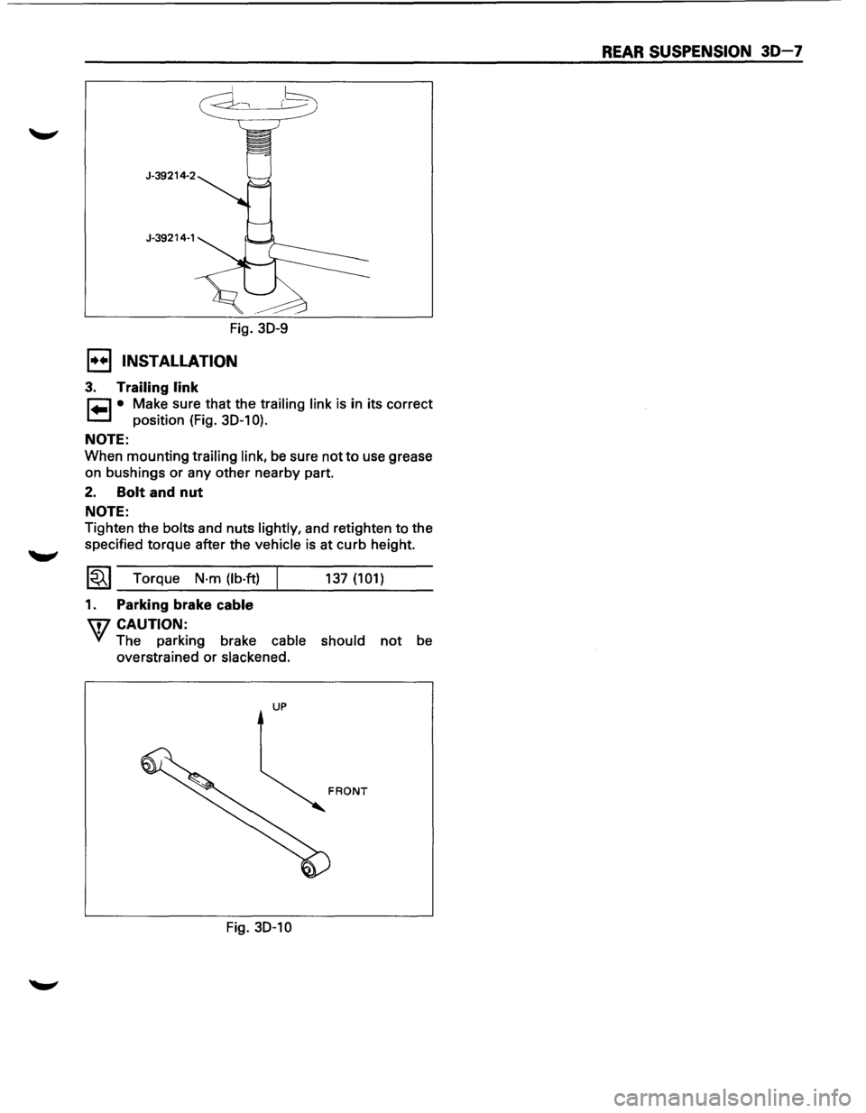
Fig. 30-9
1••1 INSTALLATION
3. Trailing link
~ • Make sure that the trailing link is in its correct
1.=.1 position (Fig. 30-1 0).
NOTE:
When mounting trailing link, be sure not to use grease
on bushings or any other nearby part.
2. Bolt and nut
NOTE:
Tighten the bolts and nuts lightly, and retighten to the
specified torque after the
vehicle is at curb height.
1~1 Torque N·m (lb·ft)
1. Parking brake cable
W CAUTION:
137 (101)
VI The parking brake cable should not be
overstrained or
slackened.
UP
Fig. 30-10
REAR SUSPENSION 30-7
Page 195 of 1928
r-:::::1 )--~
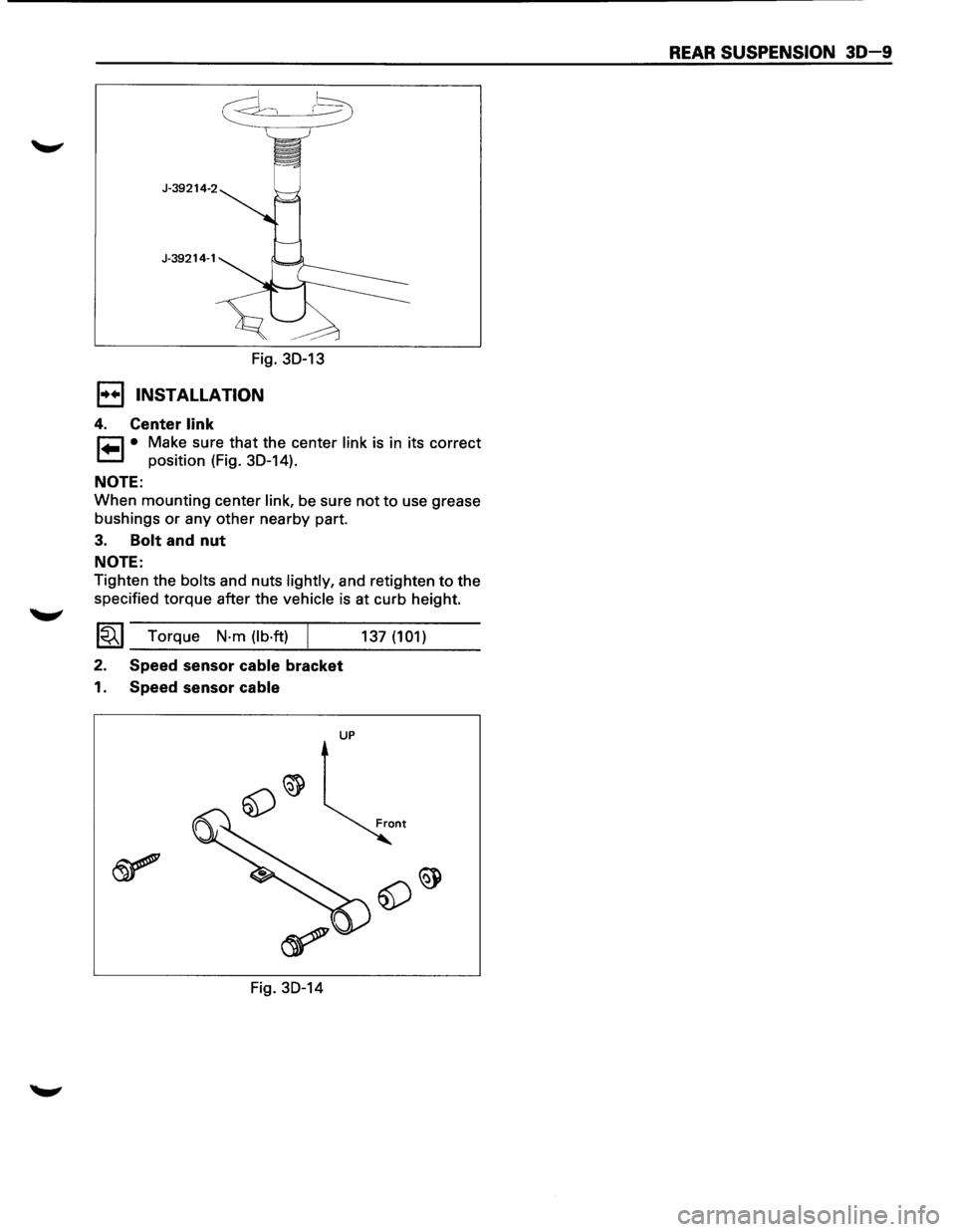
Fig. 30-13
I•+ I INSTALLATION
4. Center link
r=l • Make sure that the center link is in its correct
1.=.1 position (Fig. 30-14).
NOTE:
When mounting center link, be sure not to use grease
bushings
or any other nearby part.
3. Bolt and nut
NOTE:
Tighten the bolts and nuts lightly, and retighten to the
specified torque after the
vehicle is at curb height.
~~~ Torque N·m (lb·ft) /
2. Speed sensor cable bracket
1. Speed sensor cable
UP
Fig. 30-14 137
(101)
REAR SUSPENSION 30-9
Page 197 of 1928
J-39792-1
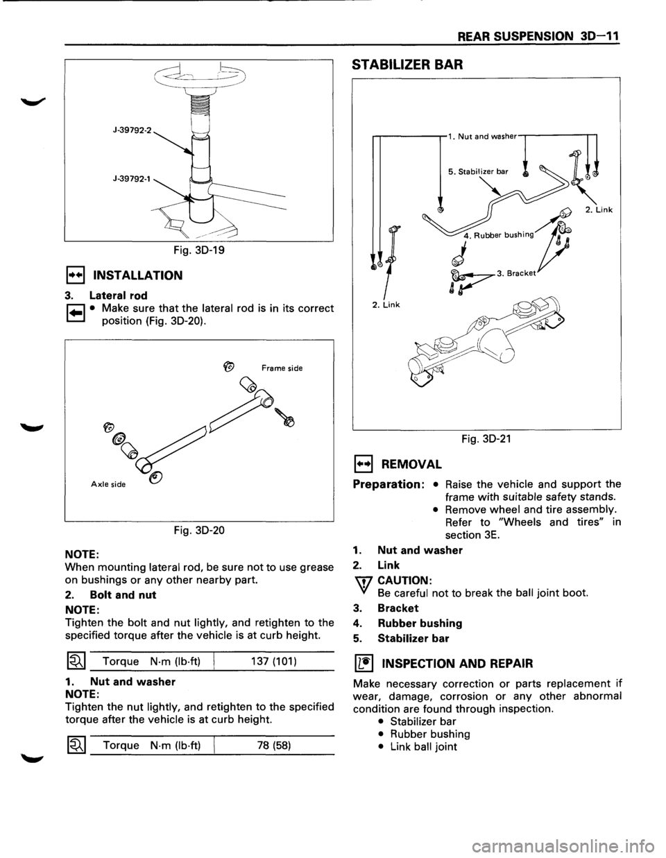
Fig. 30-19
1•+1 INSTALLATION
3. Lateral rod
~ • Make sure that the lateral rod is in its correct
~ position (Fig. 30-20).
Frame side
Axle side
Fig. 30-20
NOTE:
When mounting lateral rod, be sure not to use grease
on bushings
or any other nearby part.
2. Bolt and nut
NOTE:
Tighten the bolt and nut lightly, and retighten to the
specified torque after the
vehicle is at curb height.
~~~ Torque N·m (lb·ft)
1. Nut and washer
NOTE:
137 (101)
Tighten the nut lightly, and retighten to the specified
torque after the
vehicle is at curb height.
1~1 Torque N·m (lb·ft) 78 (58)
REAR SUSPENSION 30-11
STABILIZER BAR
2. Link
Fig. 30-21
EJ REMOVAL
Preparation: • Raise the vehicle and support the
frame
with suitable safety stands.
• Remove wheel and tire assembly.
Refer
to "Wheels and tires" in
section
3E.
1. Nut and washer
2. Link
\fl CAUTION:
VI Be careful not to break the ball joint boot.
3. Bracket
4. Rubber bushing
5. Stabilizer bar
[!] INSPECTION AND REPAIR
Make necessary correction or parts replacement if
wear, damage, corrosion or any other abnormal
condition are found through inspection.
• Stabilizer bar
• Rubber bushing
• Link ball joint
Page 201 of 1928
WHEELS AND TIRES 3E-1
SECTION 3E
WHEELS AND TIRES
W CAUTION:
When fasteners are removed, always reinstall them at the same location from which they were removed.
If a fastener needs to be replaced, use the correct part number fastener for that application. If the correct
part
number fastener is not available, a fastener of equal size and strength (or stronger) may be used.
Fasteners
that are not reused, and those requiring thread locking compound, will be called out. The correct
torque value must be used when installing fasteners that require it. If the above conditions are not
followed, parts or system damage could result.
CONTENTS
General Description . . . . . . . . . . . . . . . . . . . . . . . . . . . . . . . 3 E -1 Unit Repair .......................................... 3E-7
Diagnosis ........................................... 3E-2 Tires ............................................... 3E-7
Irregular and Premature Wear ................ 3E-2 Wheels ............................................ 3E-7
Inflation of Tires ................................. 3 E- 3 General Balance Procedure ................... 3E-8
Diagnosis List. . . . . . . . . . . . . . . . . . . . . . . . . . . . . . . . . . . . 3 E- 3 Balancing Wheel and Tire ...................... 3E-8
On-Vehicle Service ................................ 3E-6 Main Data and Specifications .................... 3E-9
Wheels ............................................ 3E-6 General Specifications ......................... 3E-9
Torque Specifications .......................... 3E-9
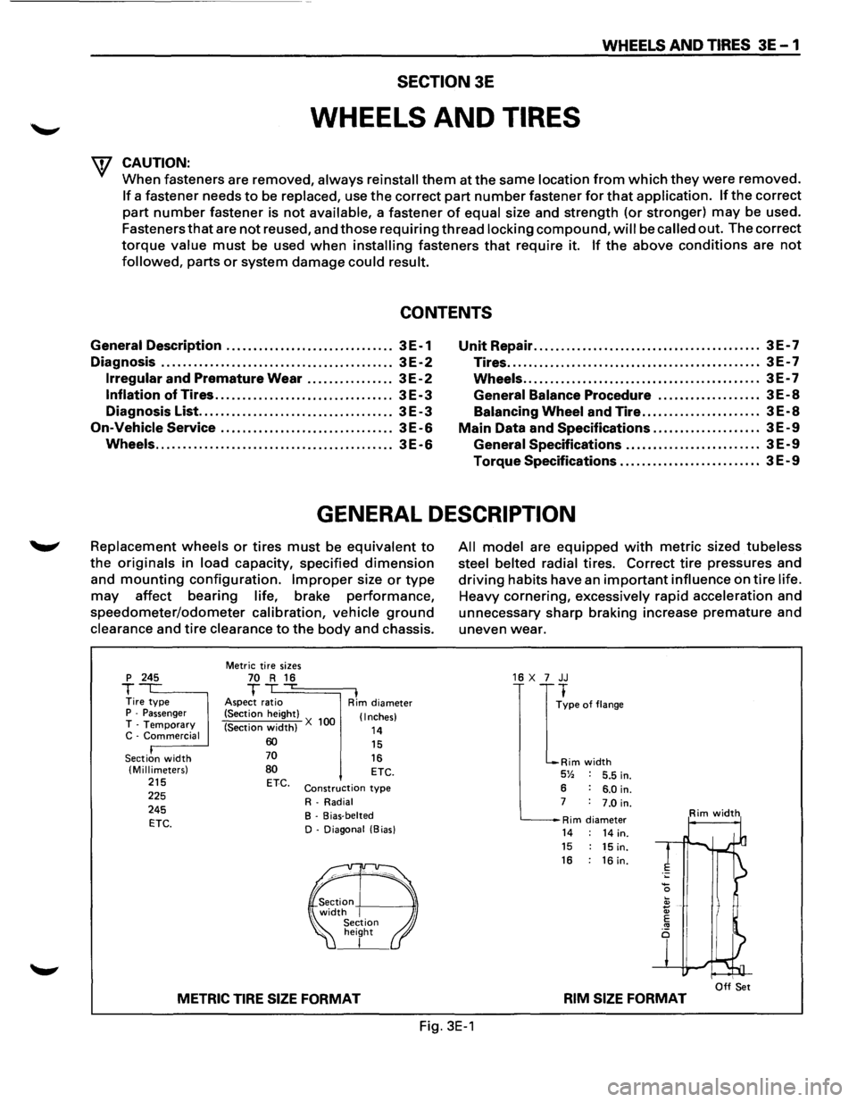
GENERAL DESCRIPTION
Replacement wheels or tires must be equivalent to
the originals in load capacity, specified dimension
and mounting configuration. Improper size or type
may affect bearing life, brake performance,
speedometer/odometer calibration, vehicle ground
clearance and tire clearance to the body and chassis.
p 245
T Tire type P -Passenger T -Temporary C -Commercial
Section
width (Millimeters) 215 225
245
ETC.
Metric tire sizes 70 R 16 T ,...
Aspect ratio I Rim diameter
(Section height)
(Section
width) X 100 (Inches)
14 60 70
80 ETC.
15
16 ETC.
Construction type
R-Radial
B - Bias-belted
D - Diagonal (Bias)
METRIC TIRE SIZE FORMAT
All model are equipped with metric sized tubeless
steel belted radial
tires. Correct tire pressures and
driving habits have an important influence on tire life.
Heavy cornering, excessively rapid acceleration and
unnecessary sharp braking increase
premature and
uneven wear.
16 X 7 JJ
I
~pe of flange
Rim width 5% 5.5 in.
6 6.0 in. 7 7.0 in.
Rim diameter Rim width
14 14 in. 15 15 in. 16 : 16 in.
I Off Set RIM SIZE FORMAT
Fig. 3E-1
Page 321 of 1928
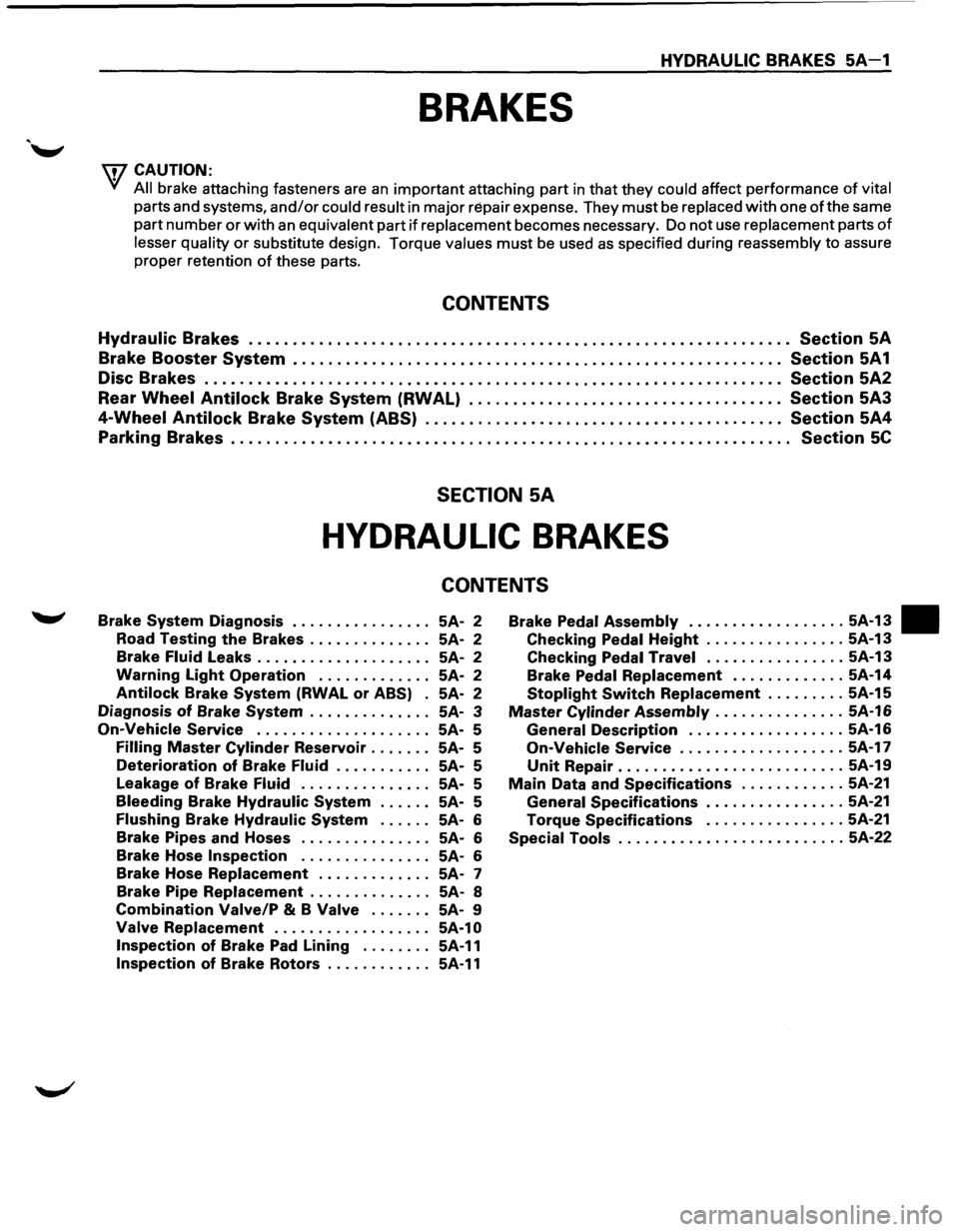
HYDRAULIC BRAKES SA-1
BRAKES
w CAUTION:
• All
brake attaching fasteners are an important attaching part in that they could affect performance of vital
parts and systems, and/or could result in major repair expense. They must be replaced with one of the same
part
number or with an equivalent part if replacement becomes necessary. Do not use replacement parts of
lesser quality or substitute design. Torque values must be used as specified during reassembly to assure
proper retention
of these parts.
CONTENTS
Hydraulic Brakes . . . . . . . . . . . . . . . . . . . . . . . . . . . . . . . . . . . . . . . . . . . . . . . . . . . . . . . . . . . . . . Section SA
Brake Booster System ........................................................ Section 5A1
Disc Brakes . . . . . . . . . . . . . . . . . . . . . . . . . . . . . . . . . . . . . . . . . . . . . . . . . . . . . . . . . . . . . . . . . . Section 5A2
Rear
Wheel Antilock Brake System (RWAL) .................................... Section 5A3
4-Wheel Antilock Brake System (ABS) ......................................... Section 5A4
Parking Brakes . . . . . . . . . . . . . . . . . . . . . . . . . . . . . . . . . . . . . . . . . . . . . . . . . . . . . . . . . . . . . . . .
Section 5C
SECTION 5A
HYDRAULIC BRAKES
CONTENTS
Brake System Diagnosis ................ SA-2
Road
Testing the Brakes . . . . . . . . . . . . . . SA-2
Brake
Fluid Leaks . . . . . . . . . . . . . . . . . . . . SA-2
Warning Light Operation . . . . . . . . . . . . . SA-2
Antilock Brake System (RWAL or ABS) . SA- 2
Diagnosis of Brake System . . . . . . . . . . . . . . SA-3
On-Vehicle Service .................... SA- S
Filling Master Cylinder Reservoir . . . . . . . SA-S
Deterioration of Brake Fluid . . . . . . . . . . . SA-S
Leakage
of Brake Fluid . . . . . . . . . . . . . . . SA-S
Bleeding Brake Hydraulic System . . . . . . SA-S
Flushing Brake Hydraulic System . . . . . . SA-6
Brake Pipes
and Hoses . . . . . . . . . . . . . . . SA-6
Brake Hose
Inspection . . . . . . . . . . . . . . . SA-6
Brake Hose
Replacement . . . . . . . . . . . . . SA-7
Brake Pipe
Replacement . . . . . . . . . . . . . . SA-8
Combination Valve/P & B Valve . . . . . . . SA-9
Valve Replacement . . . . . . . . . . . . . . . . . . SA-1 0
Inspection of Brake Pad Lining . . . . . . . . SA-11
Inspection of Brake Rotors . . . . . . . . . . . . SA-11
Brake Pedal Assembly .................. SA-13 •
Checking Pedal Height ................ SA-13
Checking Pedal Travel ................ SA-13
Brake
Pedal Replacement ............. SA-14
Stoplight Switch Replacement ......... SA-1S
Master Cylinder Assembly ............... SA-16
General Description .................. SA-16
On-Vehicle Service ................... SA-17
Unit Repair .......................... SA-19
Main Data and Specifications ............ SA-21
General Specifications ................ SA-21
Torque Specifications ................ SA-21
Special Tools .......................... SA-22
Page 324 of 1928
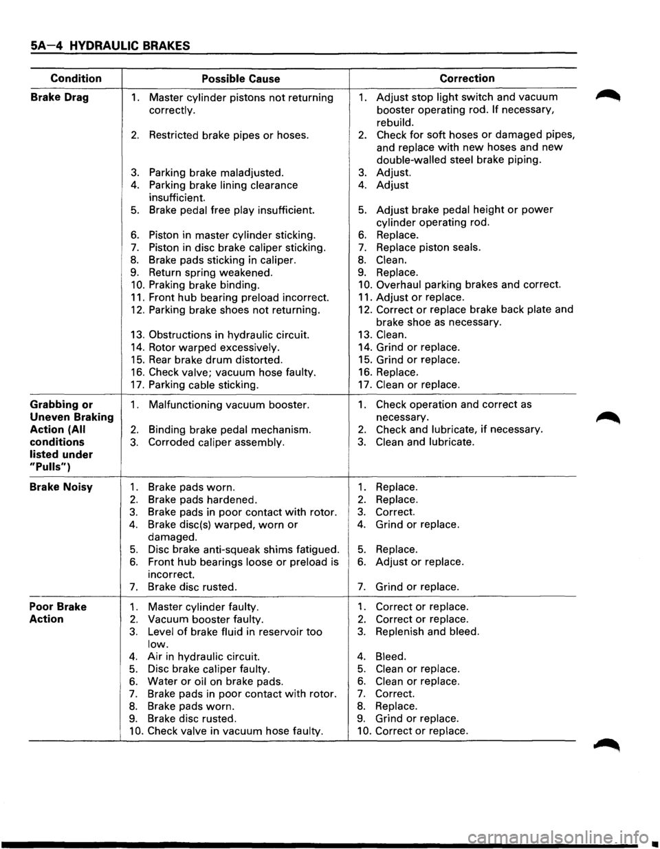
SA-4 HYDRAULIC BRAKES
Condition Possible Cause Correction
Brake Drag
1. Master cylinder pistons not returning 1. Adjust stop light switch and vacuum
correctly. booster operating rod. If necessary,
rebuild.
2. Restricted brake pipes or hoses. 2. Check for soft hoses or damaged pipes,
and
replace with new hoses and new
double-walled steel brake piping.
3. Parking brake maladjusted. 3. Adjust.
4. Parking brake lining clearance 4. Adjust
insufficient.
5. Brake pedal free play insufficient. 5. Adjust brake pedal height or power
cylinder operating rod.
6. Piston in master cylinder sticking. 6. Replace.
7. Piston in disc brake caliper sticking. 7. Replace piston seals.
8. Brake pads sticking in caliper. 8. Clean.
9. Return spring weakened. 9. Replace.
10. Praking brake binding. 10. Overhaul parking brakes and correct.
11. Front hub bearing preload incorrect. 11.
Adjust or replace.
12. Parking brake shoes not returning. 12.
Correct or replace brake back plate and
brake shoe
as necessary.
13. Obstructions in hydraulic circuit. 13. Clean.
14. Rotor warped excessively. 14.
Grind or replace.
15. Rear brake drum distorted. 15.
Grind or replace.
16. Check valve; vacuum hose faulty. 16. Replace.
17. Parking cable sticking. 17. Clean or replace.
Grabbing
or 1. Malfunctioning vacuum booster. 1. Check operation and correct as
Uneven Braking necessary.
Action
(All 2. Binding brake pedal mechanism. 2. Check and lubricate, if necessary.
conditions
3. Corroded caliper assembly. 3. Clean and lubricate.
listed
under
"Pulls")
Brake Noisy 1 . Brake pads worn. 1. Replace.
2. Brake pads hardened. 2. Replace.
3. Brake pads in poor contact with rotor. 3. Correct.
4. Brake disc(s) warped, worn or 4. Grind or replace.
damaged.
5. Disc brake anti-squeak shims fatigued. 5. Replace.
6. Front hub bearings loose or preload is 6. Adjust or replace.
incorrect.
7. Brake disc rusted. 7. Grind or replace.
Poor Brake 1. Master cylinder faulty. 1. Correct or replace.
Action 2. Vacuum booster faulty. 2. Correct or replace.
3. Level of brake fluid in reservoir too 3. Replenish and bleed.
low.
4. Air in hydraulic circuit. 4. Bleed.
5. Disc brake caliper faulty. 5. Clean or replace.
6. Water or oil on brake pads. 6. Clean or replace.
7. Brake pads in poor contact with rotor. 7. Correct.
8. Brake pads worn. 8. Replace.
9. Brake disc rusted. 9. Grind or replace.
10. Check valve in vacuum hose faulty. 10. Correct or replace.
•
Page 333 of 1928
HYDRAULIC BRAKES SA-13
BRAKE PEDAL ASSEMBL V
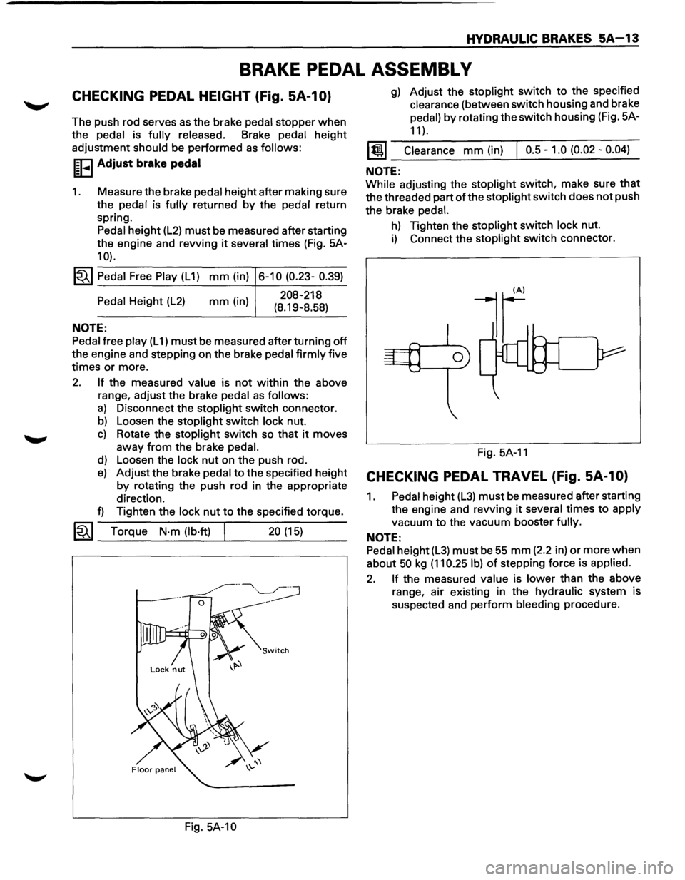
CHECKING PEDAL HEIGHT (Fig. SA-1 0)
The push rod serves as the brake pedal stopper when
the pedal is fully released. Brake pedal height
adjustment
should be performed as follows:
I~FI Adjust brake pedal
1. Measure the brake pedal height after making sure
the pedal is
fully returned by the pedal return
spring. Pedal height
(L2) must be measured after starting
the engine and revving
it several times (Fig. 5A-
10).
1~1 Pedal Free Play (L 1) mm (in) 6-10 (0.23- 0.39)
Pedal Height (L2)
NOTE:
mm (in) 208-218
(8.19-8.58)
Pedal free play (L 1) must be measured after turning off
the engine and stepping on the brake pedal firmly five
times
or more.
2. If the measured value is not within the above
range, adjust the brake
pedal as follows:
a) Disconnect the stoplight switch connector.
b) Loosen the stoplight switch lock nut.
c) Rotate the stoplight switch so that it moves
away
from the brake pedal.
d) Loosen the lock nut on the push rod.
e) Adjust the brake pedal to the specified height
by rotating the push rod in the appropriate
direction.
f) Tighten the lock nut to the specified torque.
~~~ Torque N·m (lb·ft) 20 (15) --------~----~---
Fig. 5A-10
g) Adjust the stoplight switch to the specified
clearance (between switch housing and brake
pedal)
by rotating the switch housing (Fig. 5A-
11 ).
1@1 Clearance mm (in) I 0.5-1.0 (0.02-0.04)
NOTE:
While adjusting the stoplight switch, make sure that
the threaded part of the stoplight switch does not push
the brake
pedal.
h) Tighten the stoplight switch lock nut.
i) Connect the stoplight switch connector.
Fig.
5A-11
CHECKING PEDAL TRAVEL (Fig. SA-1 0)
1. Pedal height (L3) must be measured after starting
the engine and revving
it several times to apply
vacuum
to the vacuum booster fully.
NOTE:
Pedal height (L3) must be 55 mm (2.2 in) or more when
about 50 kg (11 0.25 I b) of stepping force is applied.
2. If the measured value is lower than the above
range, air existing in the hydraulic system is
suspected and perform bleeding procedure.
Page 341 of 1928
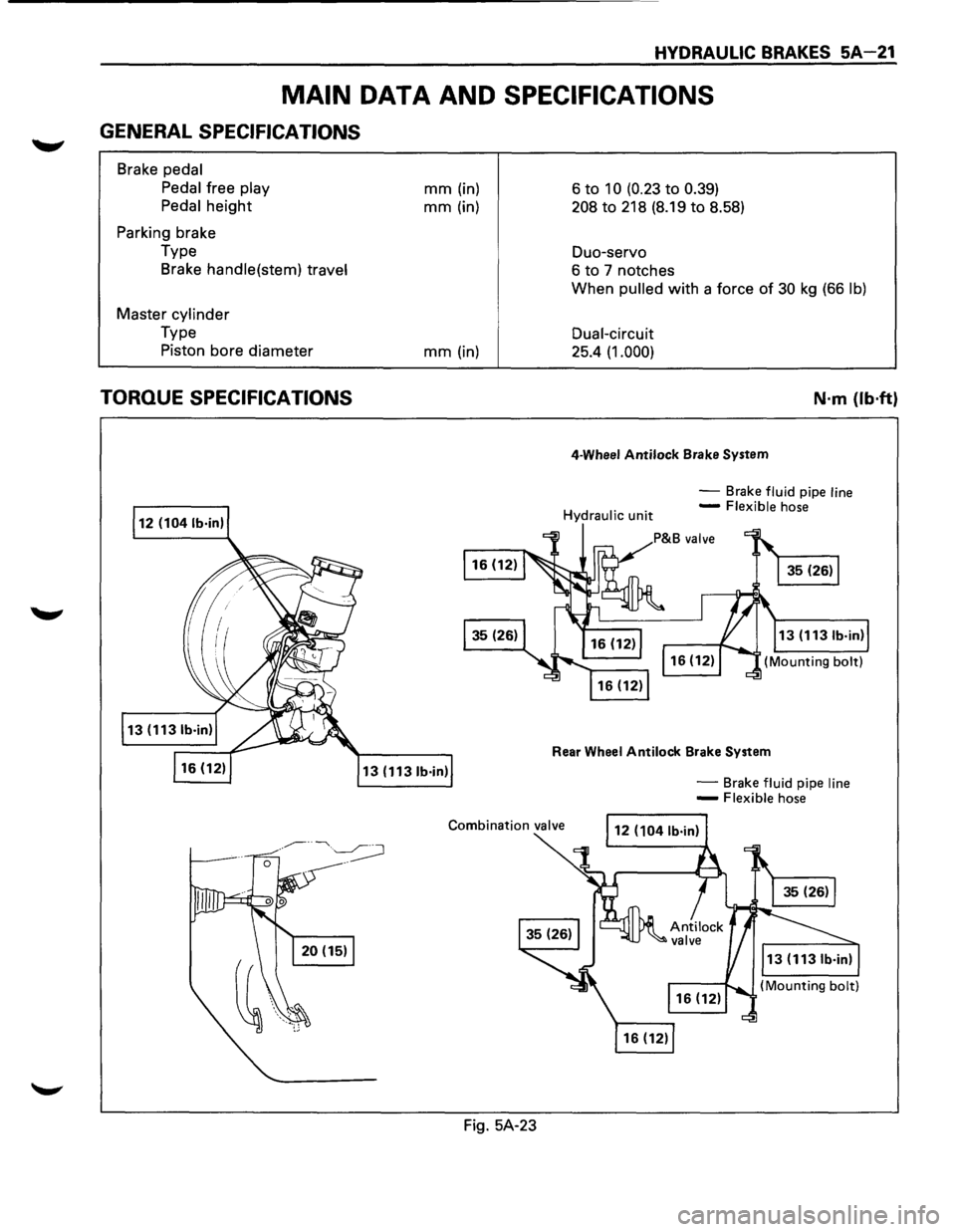
HYDRAULIC BRAKES 5A-21
MAIN DATA AND SPECIFICATIONS
GENERAL SPECIFICATIONS
Brake pedal
Pedal
free play
Pedal
height
Parking brake
Type Brake
handle(stem) travel
Master cylinder
Type
Piston bore diameter
TORQUE SPECIFICATIONS
mm (in)
mm (in)
mm (in)
13 (1131b·in)
Fig. 5A-23 6
to 10 (0.23 to 0.39)
208 to 218
(8.19 to 8.58)
Duo-servo
6 to 7 notches
When
pulled with a force of 30 kg (66 lb)
Dual-circuit
25.4 (1.000)
4-Wheel Antilock Brake System
N·m {lb·ft}
-Brake fluid pipe line -Flexible hose
Rear Wheel Antilock Brake System
-Brake fluid pipe line -Flexible hose
Page 518 of 1928
6A-2 GENERAL ENGINE MECHANICAL
NOTE:
•
During disassembly, be sure that the valve train
components are kept
together and identified so
that they can be re-installed in their original
locations.
• Before removing the cylinder head from the
engine and before disassembling the valve
mechanism, perform a compression test and note
the results.
1•! .. 1 DISASSEMBLY
(SOHC)
1. Camshaft timing pulley
2. Front plate
3. Camshaft bracket fixing bolts
4. Camshaft, oil seal and camshaft end plug
• Remove them with camshaft bracket.
5. Rockershaft assembly (Exhaust side)
6. Rockershaft assembly (Intake side)
7. Spark plug
\fl CAUTION:
VI • Do not remove the spark plugs when the head
and plugs are hot.
• Clean dirt and debris from spark plug recess
areas.
(DOHC)
1. Camshaft timing pulley
2. Front plate
3. Camshaft bracket fixing bolts
4. Chain tensioner fixing bolts
5. Camshaft, oil seal and camshaft end plug
• Remove them with chain and chain tensioner
6. Swing arm.
7. Hydraulic lash adjusters (HLA)
NOTE:
Immerse HLA in engine oil, taking care nottoturn it
upside down or sideways in order to prevent any
air
from entering into HLA.
8. Spark plug
\flCAUTION:
VI • Do not remove the spark plugs when the head
and plugs are hot.
• Clean dirt and debris from spark plug recess
areas.
f}l CLEAN
• Cylinder head
Carefully remove
all varnish, soot and carbon
to the bare metal. Do not use a motorized wire
brush on any gasket sealing surface.
IL'~'IINSPECTION AND REPAIR
• Cylinder head gasket and mating surfaces for
leaks, corrosion and blow-by. If the gasket has
failed, determine the cause. Insufficient
torque on head bolts
Improper installation
Loose
or warped cylinder head
Missing
dowel pins
- Warped case surface
1. Cylinder head bolts for damaged threads or
stretching and damaged heads caused by
improper use of tools.
\fl CAUTION:
VI Replace used cylinder head bolts.
2. Cylinder head for cracks, especially between valve
seats and in the exhaust ports.
3. Cylinder head deck for corrosion, sand particles in
head and porosity.
\fl CAUTION:
VI Do not attemptto weld the cylinder head. Replace
it.
4. Cylinder head deck, intake and exhaust manifold
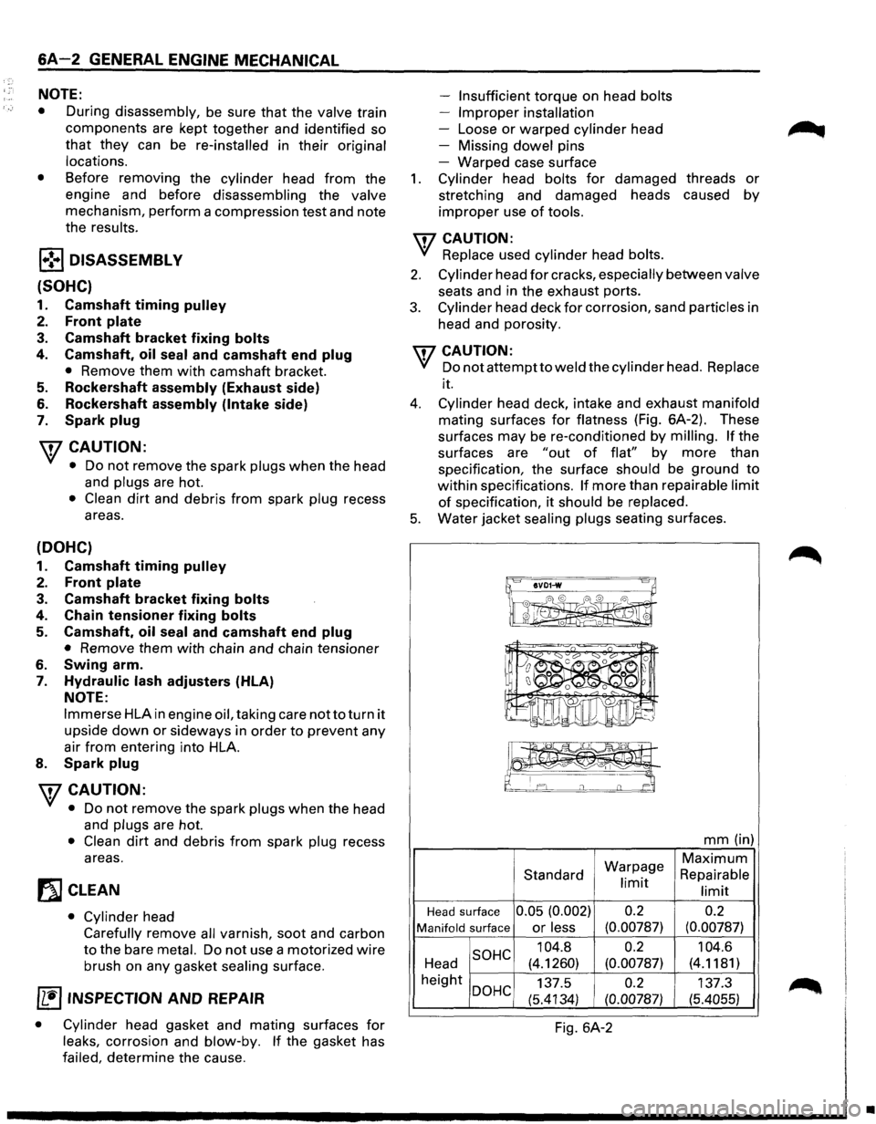
mating surfaces for flatness (Fig. 6A-2). These
surfaces
may be re-conditioned by milling. If the
surfaces are
"out of flat" by more than
specification, the surface should be ground
to
within specifications. If more than repairable limit
of specification, it should be replaced.
5. Water jacket sealing plugs seating surfaces.
IIVD1-w 8~
~ I 0 I ' 0 0 I 0
mm (in)
Warpage
Maximum
Standard Repairable limit limit
Head surface 0.05 (0.002) 0.2
0.2
Manifold surface or less (0.00787) (0.00787)
SOHC 104.8 0.2
104.6
Head (4.1260) (0.00787) (4.1181)
height
DOHC 137.5 0.2 137.3
(5.4134)
(0.00787) (5.4055)
Fig. 6A-2
•