height ISUZU TROOPER 1995 Owner's Manual
[x] Cancel search | Manufacturer: ISUZU, Model Year: 1995, Model line: TROOPER, Model: ISUZU TROOPER 1995Pages: 1928
Page 521 of 1928
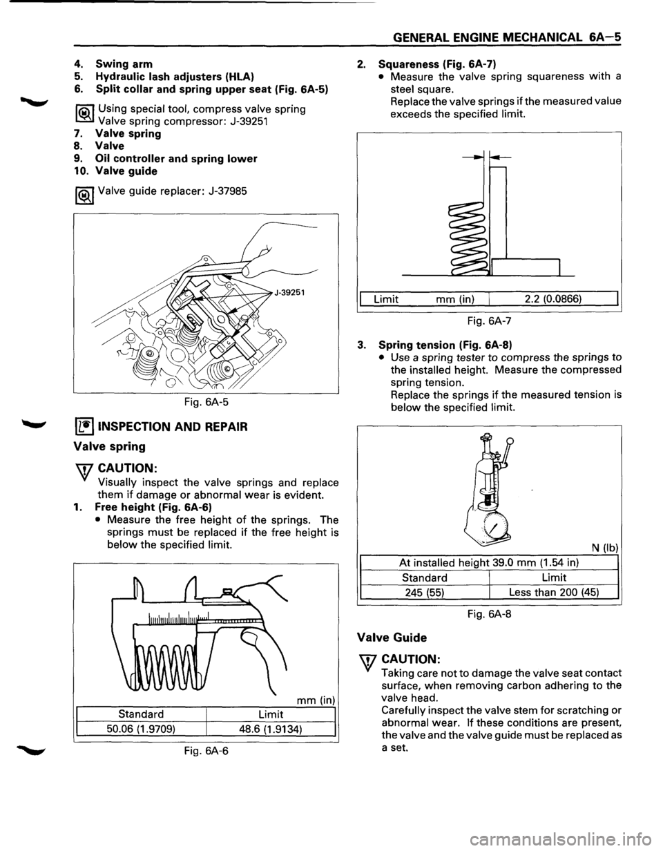
4. Swing arm
5. Hydraulic lash adjusters (HLA)
6. Split collar and spring upper seat (Fig. 6A-5)
l'iS\1 Using special tool, compress valve spring
~ Valve spring compressor: J-39251
7. Valve spring
8.
Valve
9. Oil controller and spring lower
10. Valve guide
1®..1 Valve guide replacer: J-37985
Fig. 6A-5
IL•IINSPECTION AND REPAIR
Valve spring
\fCAUTION:
Visually inspect the valve springs and replace
them
if damage or abnormal wear is evident.
1. Free height (Fig. 6A-6)
• Measure the free height of the springs. The
springs
must be replaced if the free height is
below the specified limit.
mm (in)
Standard Limit
50.06 (1.9709)
48.6 (1.9134)
Fig. 6A-6
GENERAL ENGINE MECHANICAL 6A-5
2. Squareness (Fig. 6A-7)
• Measure the valve spring squareness with a
steel square.
Replace the
valve springs if the measured value
exceeds the specified limit.
Limit mm (in) 2.2 (0.0866)
Fig. 6A-7
3. Spring tension (Fig. 6A-8)
• Use a spring tester to compress the springs to
the installed height. Measure the compressed
spring tension.
Replace the springs
if the measured tension is
below the specified limit.
N
(lb)
At installed height 39.0 mm (1.54 in)
Standard Limit
245
(55) Less than 200 (45)
Fig. 6A-8
Valve Guide
\fCAUTION:
Taking care not to damage the valve seat contact
surface, when removing carbon adhering to the
valve head.
Carefully inspect the valve stem for scratching or
abnormal wear.
If these conditions are present,
the
valve and the valve guide must be replaced as
a set.
Page 522 of 1928
6A-6 GENERAL ENGINE MECHANICAL
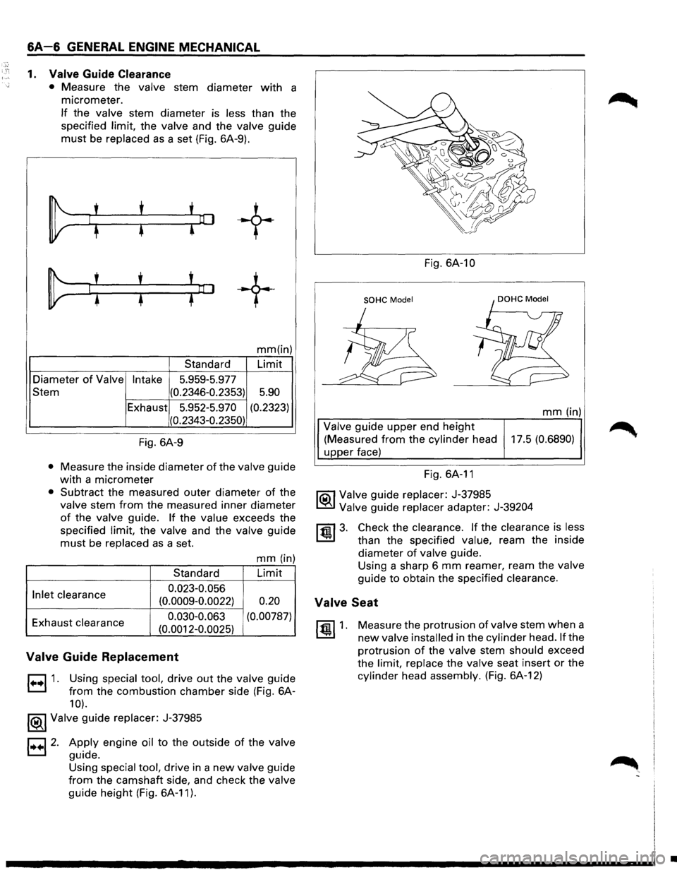
1. Valve Guide Clearance
• Measure the valve stem diameter with a
micrometer.
If the valve stem diameter is less than the
specified
limit, the valve and the valve guide
must be replaced as a set (Fig. 6A-9).
~
1: : !o:J
+
~ li : :~
+
mm(in)
Standard Limit
Diameter
of Valve Intake 5.959-5.977
Stem (0.2346-0.2353)
5.90
Exhaust 5.952-5.970 (0.2323)
(0.2343-0.2350)
Fig. 6A-9
• Measure
the inside diameter of the valve guide
with a micrometer
• Subtract the measured outer diameter of the
valve stem from the measured inner diameter
of the valve guide. If the value exceeds the
specified
limit, the valve and the valve guide
must be replaced as a set.
mm (in)
Standard Limit
Inlet
clearance 0.023-0.056
(0.0009-0.0022) 0.20
Exhaust clearance 0.030-0.063
(0.00787)
(0.0012-0.0025)
Valve Guide Replacement
r::l 1. Using special tool, drive out the valve guide
L::.l from the combustion chamber side (Fig. 6A-
10).
1®..1 Valve guide replacer: J-37985
1••12. Apply engine oil to the outside of the valve
guide.
Using
special tool, drive in a new valve guide
from the camshaft side, and check the valve
guide height (Fig. 6A-11 ).
Fig. 6A-1 0
SOHC Model
mm (in)
Valve guide upper end height
(Measured from the
cylinder head 17.5 (0.6890)
upper face)
Fig. 6A-11
li0\1 Valve guide replacer: J-37985
~ Valve guide replacer adapter: J-39204
~3. Check the clearance. If the clearance is less
than the specified value, ream the inside
diameter
of valve guide.
Using a sharp 6
mm reamer, ream the valve
guide to obtain the specified clearance.
Valve Seat
~1. Measure the protrusion of valve stem when a
new valve installed in the cylinder head. If the
protrusion
of the valve stem should exceed
the
limit, replace the valve seat insert or the
cylinder head assembly. (Fig. 6A-12)
•
Page 527 of 1928
GENERAL ENGINE MECHANICAL 6A-11
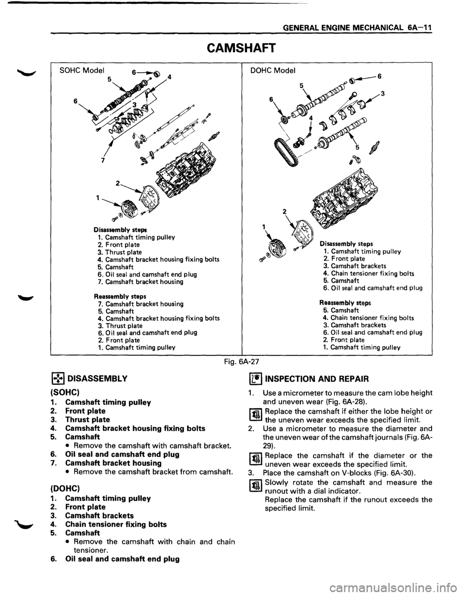
CAMSHAFT
SOHC Model
6 7
1
Disassembly steps
1. Camshaft timing pulley
2. Front plate
3. Thrust plate 4. Camshaft bracket housing fixing bolts
5. Camshaft 6. Oil seal and camshaft end plug
7. Camshaft bracket housing
Reassembly steps
7. Camshaft bracket housing 5. Camshaft
4. Camshaft bracket housing fixing bolts
3.
Thrust plate
6. Oil seal and camshaft end plug
2. Front plate 1. Camshaft timing pulley
DOHC Model
Disassembly steps
1. Camshaft timing pulley 2. Front plate
3. Camshaft brackets
4. Chain tensioner fixing bolts
5. Camshaft
6. Oil seal and camshaft end plug
Reassembly steps
5. Camshaft
4. Chain tensioner fixing bolts
3. Camshaft brackets
6.
Oil seal and camshaft end plug 2. Front plate
1. Camshaft timing pulley
Fig. 6A-27
1.-!•l DISASSEMBLY
(SOHC)
1. Camshaft timing pulley
2. Front plate
3. Thrust plate
4. Camshaft bracket housing fixing bolts
5. Camshaft
• Remove the camshaft with camshaft bracket.
6. Oil seal and camshaft end plug
7. Camshaft bracket housing
• Remove the camshaft bracket from camshaft.
(OOHC)
1. Camshaft timing pulley
2. Front plate
3. Camshaft brackets
4. Chain tensioner fixing bolts
5. Camshaft
• Remove the camshaft with chain and chain
tensioner.
6. Oil seal and camshaft end plug
IL•IINSPECTION AND REPAIR
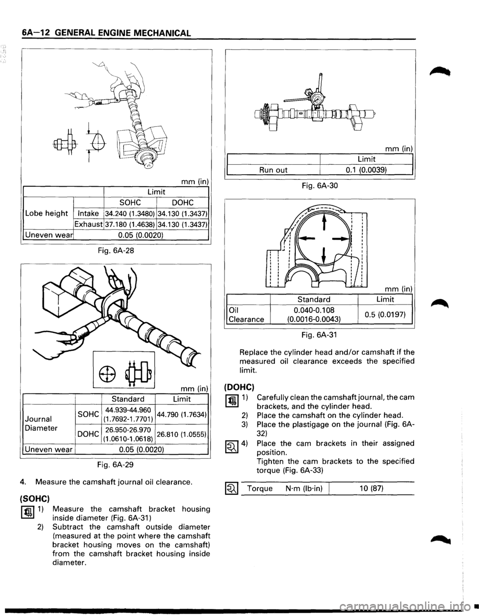
1. Use a micrometer to measure the cam lobe height
and uneven
wear (Fig. 6A-28).
Hffil Replace the camshaft if either the lobe height or
l..!:l the uneven wear exceeds the specified limit.
2. Use a micrometer to measure the diameter and
the uneven wear
of the camshaft journals (Fig. 6A-
29).
Hffil Replace the camshaft if the diameter or the
l..!:l uneven wear exceeds the specified limit.
3. Place the camshaft on V-blocks (Fig. 6A-30).
rfiil Slowly rotate the camshaft and measure the
l..!:l runout with a dial indicator.
Replace the camshaft if the runout exceeds the
specified
limit.
Page 528 of 1928
6A-12 GENERAL ENGINE MECHANICAL
mm (in)
Limit
SOHC DOHC
Lobe height Intake 34.240 (1.3480) 34.130 (1.3437)
Exhaust 37.180 (1.4638) 34.130 (1.3437)
Uneven wear 0.05 (0.0020)
Journal
Diameter
Uneven
wear
Fig. 6A-28
mm (in)
Standard Limit
44.939-44.960 SOHC (1.
7692 _
1 _7701) 44.790 (1.7634)
26.950-26.970 DOHC (1 _
0610 _
1 _
0618 )
26.810 (1.0555)
0.05 (0.0020)
Fig. 6A-29
4. Measure the camshaft journal oil clearance.
(SOHC)
~1) Measure the camshaft bracket housing
inside diameter (Fig. 6A-31)
2) Subtract the camshaft outside diameter
(measured at the
point where the camshaft
bracket housing moves on the camshaft)
from the camshaft bracket housing inside
diameter.
mm (in)
Limit
Run out 0.1 (0.0039)
Fig. 6A-30
mm (in)
Limit
Oil
Clearance
0.040-0.1 08
(0.0016-0.0043) 0.5
(0.0197)
Fig. 6A-31
Replace the cylinder head
and/or camshaft if the
measured oil clearance exceeds the specified
limit.
(DOHC)
~1) Carefully clean the camshaft journal, the cam
brackets, and the
cylinder head.
2) Place the camshaft on the cylinder head.
3) Place the plastigage on the journal (Fig. 6A-
32)
~4) Place the cam brackets in their assigned
position.
Tighten the cam brackets
to the specified
torque (Fig. 6A-33)
~~~ Torque N·m (lb·in) 10 (87)
•
Page 1049 of 1928
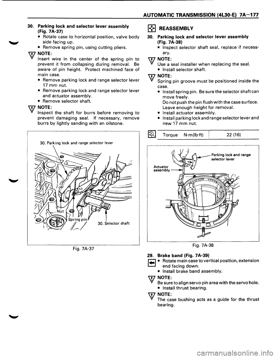
30. Parking lock and selector lever assembly
(Fig. 7A-37)
• Rotate case to horizontal position, valve body
side facing up.
• Remove spring pin, using cutting pliers.
\fl NOTE:
~ Insert wire in the center of the spring pin to
prevent it from collapsing during removal. Be
aware of pin height. Protect machined face of
main case.
• Remove parking lock and range selector lever
17 mm nut.
• Remove parking lock and range selector lever
and actuator assembly.
•
Remove selector shaft.
\fl NOTE:
~ Inspect the shaft for burrs before removing to
prevent damaging seal. If necessary, remove
burrs
by lightly sanding with an oilstone.
30. Parking lock and range selector lever
30. Selector
shaft
Fig. 7A-37
AUTOMATIC TRANSMISSION (4L30-E) 7A-177
1 .. ! .. 1 REASSEMBLY
30. Parking lock and selector lever assembly
(Fig. 7A-38)
• Inspect selector shaft seal, replace if necess
ary.
\fl NOTE:
~ Use a seal installer when replacing the seal.
• Install selector
shaft.
\fl NOTE:
~ Spring pin groove must be positioned inside the
case.
• Install spring pin. Be sure the selector shaft can
move
freely.
Do not push the pin flush with the case surface.
Leave enough
height for removal.
• Install
actuator assembly.
• Install
parking lock and range selector lever and
new 17 mm nut.
~~~ Torque N·m(lb·ft) 22 (16)
Parking lock and range selector lever
Fig. 7A-38
29. Brake band (Fig. 7A-39)
~ • Rotate main case to vertical position, extension
~ end facing down.
• Install brake band assembly.
\fl NOTE:
~ Be sure to align servo pin area with the servo hole.
• Install
thrust bearing.
\fl NOTE:
~ The case bushing acts as a guide for the thrust
bearing.
Page 1110 of 1928
78-20 MANUAL TRANSMISSION
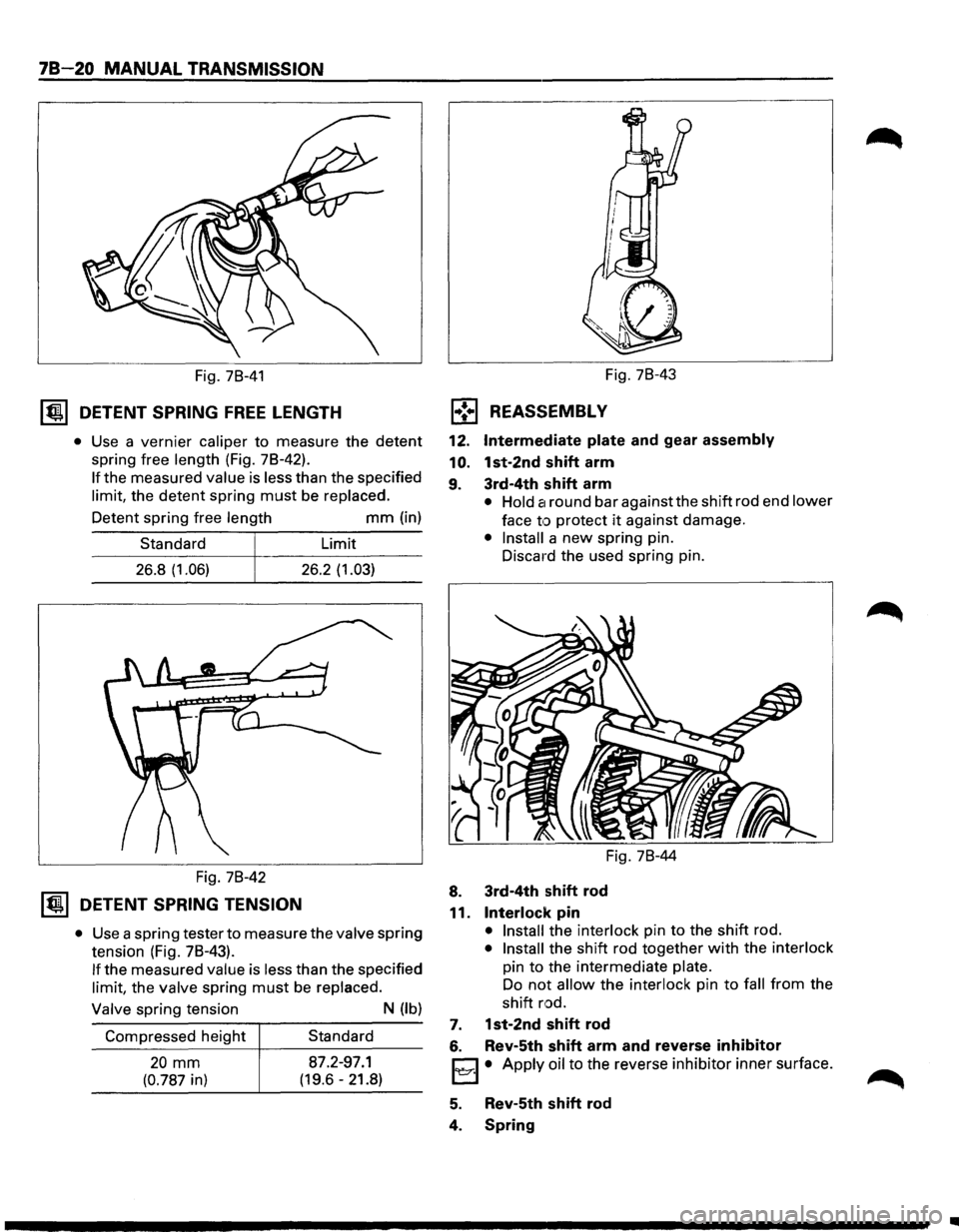
Fig. 78-41
~ DETENT SPRING FREE LENGTH
• Use a vernier caliper to measure the detent
spring free length (Fig. 78-42).
If the measured value is less than the specified
limit, the
detent spring must be replaced.
Detent spring free length
mm (in)
Standard Limit
26.8 (1.06) 26.2 (1.03)
Fig. 78-42
~ DETENT SPRING TENSION
• Use a spring tester to measure the valve spring
tension (Fig. 78-43).
If the measured value is less than the specified
limit, the valve spring must be replaced.
Valve spring tension
N (lb)
Compressed height Standard
20 mm 87.2-97.1
(0.787 in) (19.6-21.8) Fig.
78-43
l•!•l REASSEMBLY
12. Intermediate plate and gear assembly
10.
1st-2nd shift arm
9. 3rd-4th shift arm
• Hold Cl round bar against the shift rod end lower
face to protect it against damage.
• Install a new spring pin.
Discard the used spring pin.
Fig. 78-44
8. 3rd-4th shift rod
11. Interlock pin
• Install the interlock pin to the shift rod.
• Install the shift rod together with the interlock
pin
to the intermediate plate.
Do
not allow the interlock pin to fall from the
shift
rod.
7. 1st-2nd shift rod
6. Rev-5th shift arm and reverse inhibitor
EJ • Apply oil to the reverse inhibitor inner surface.
5. Rev-5th shift rod
4. Spring
..
Page 1142 of 1928
7C-8 CLUTCH
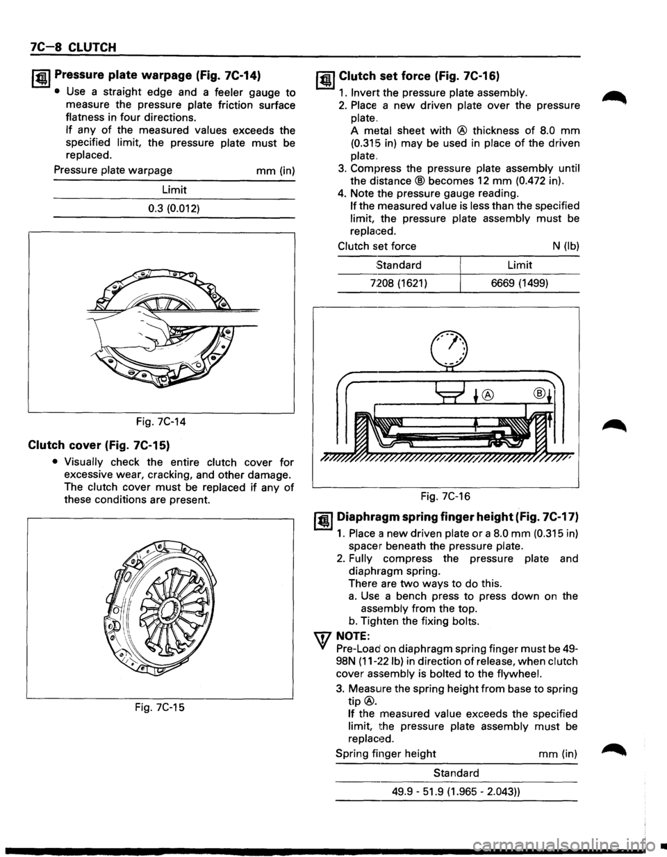
I~U Pressure plate warpage (fig. 7C-14)
• Use a straight edge and a feeler gauge to
measure the pressure plate friction surface
flatness in
four directions.
If any of the measured values exceeds the
specified limit, the pressure plate
must be
replaced.
Pressure plate warpage
Limit
0.3 (0.012)
Fig. 7C-14
Clutch cover (fig. 7C-15)
mm (in)
• Visually check the entire clutch cover for
excessive wear, cracking, and other damage.
The clutch cover
must be replaced if any of
these conditions are present.
Fig. 7C-15
jQI Clutch set force (Fig. 7C-16)
1. Invert the pressure plate assembly.
2. Place a new driven plate over the pressure
plate.
A metal sheet
with @ thickness of 8.0 mm
(0.315 in) may be used in place of the driven
plate
..
3. Compress the pressure plate assembly until
the
distance® becomes 12 mm (0.472 in).
4. Note the pressure gauge reading.
If the measured value is less than the specified
limit, the pressure plate assembly
must be
replaced.
Clutch set force N (lb)
Standard Limit
7:208 (1621) 6669 (1499)
Fig. 7C-16
1•1 Diaphragm spring finger height (fig. 7C-17)
1. Place a new driven plate or a 8.0 mm (0.315 in)
spacer beneath the pressure plate.
2. Fully compress the pressure plate and
diaphragm spring.
There are
two ways to do this.
a. Use a bench press to press down on the
asst~mbly from the top.
b. Tighten the fixing bolts.
IDNOTE:
Yf Pre-Load on diaphragm spring finger must be 49-
98N
(11-~~2 lb) in direction of release, when clutch
cover
assembly is bolted to the flywheel.
3. Measure the spring height from base to spring
tip@.
If the measured value exceeds the specified
limit, the pressure plate assembly
must be
replaced.
Spring finger height
mm (in)
Standard
49.9 -51.9 (1.965 -
2.043))
•
Page 1148 of 1928
7C 14 CLUTCH
1••1 REMOVAL
1. Pin and jaw joint pin
2. Pedal assembly and switch
3. Oil line pipe
4. Slave cylinder assembly and heat protector
5. Master cylinder assembly
6. Damper cylinder assembly
ll.•l INSPECTION AND REPAIR
Make necessary adjustments, repairs, and part
replacement
if wear, damage or other problems are
discovered during inspection.
1••1 INSTALLATION
To install, follow the removal steps in the reverse
order, noting the
following points:
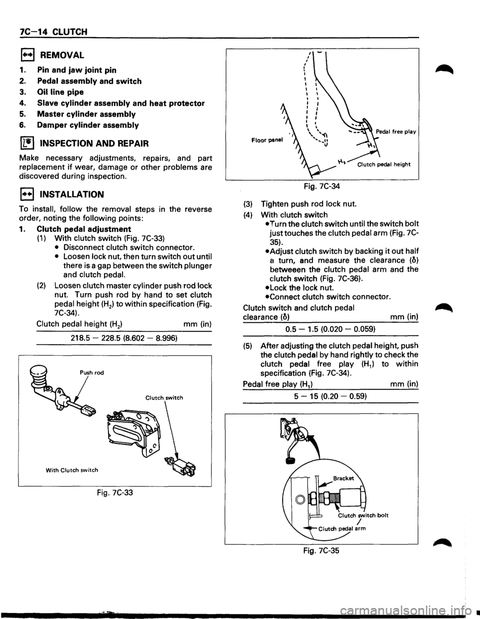
1. Clutch pedal adjustment
(1) With clutch switch (Fig. 7C-33)
• Disconnect clutch switch connector.
• Loosen lock nut, then turn switch out until
there is a gap between the switch plunger
and
clutch pedal.
(2) Loosen clutch master cylinder push rod lock
nut. Turn push rod by hand to set clutch
pedal height (H2) to
within specification (Fig.
7C-34).
Clutch
pedal height (H2 ) mm (in)
218.5
-228.5 (8.602 -8.996)
Clutch switch
With Clutch switch
Fig. 7C-33
Floor panel
Fig. 7C-34
(3) Tighten push rod lock nut.
(4) With clutch switch
Clutch pedal height
•Turn the clutch switch until the switch bolt
justtouches the clutch pedal arm (Fig. 7C
:~5).
•Adjust clutch switch by backing it out half
a
turn, and measure the clearance (o)
betweeen the clutch pedal arm and the
c:lutch switch (Fig. 7C-36).
•Lock the lock nut.
•Connect clutch switch connector.
Clutch switch and clutch
pedal
clearance
(o) mm (in)
0.5 -1.5 (0.020 -0.059)
(5) After adjusting the clutch pedal height, push
the clutch pedal
by hand rightly to check the
clutch pedal free play (H1) to within
specification (Fig. 7C-34).
Pedal free play (H1) mm (in)
5 -
15 (0.20 -0.59)
Fig. 7C-35
•
Page 1149 of 1928
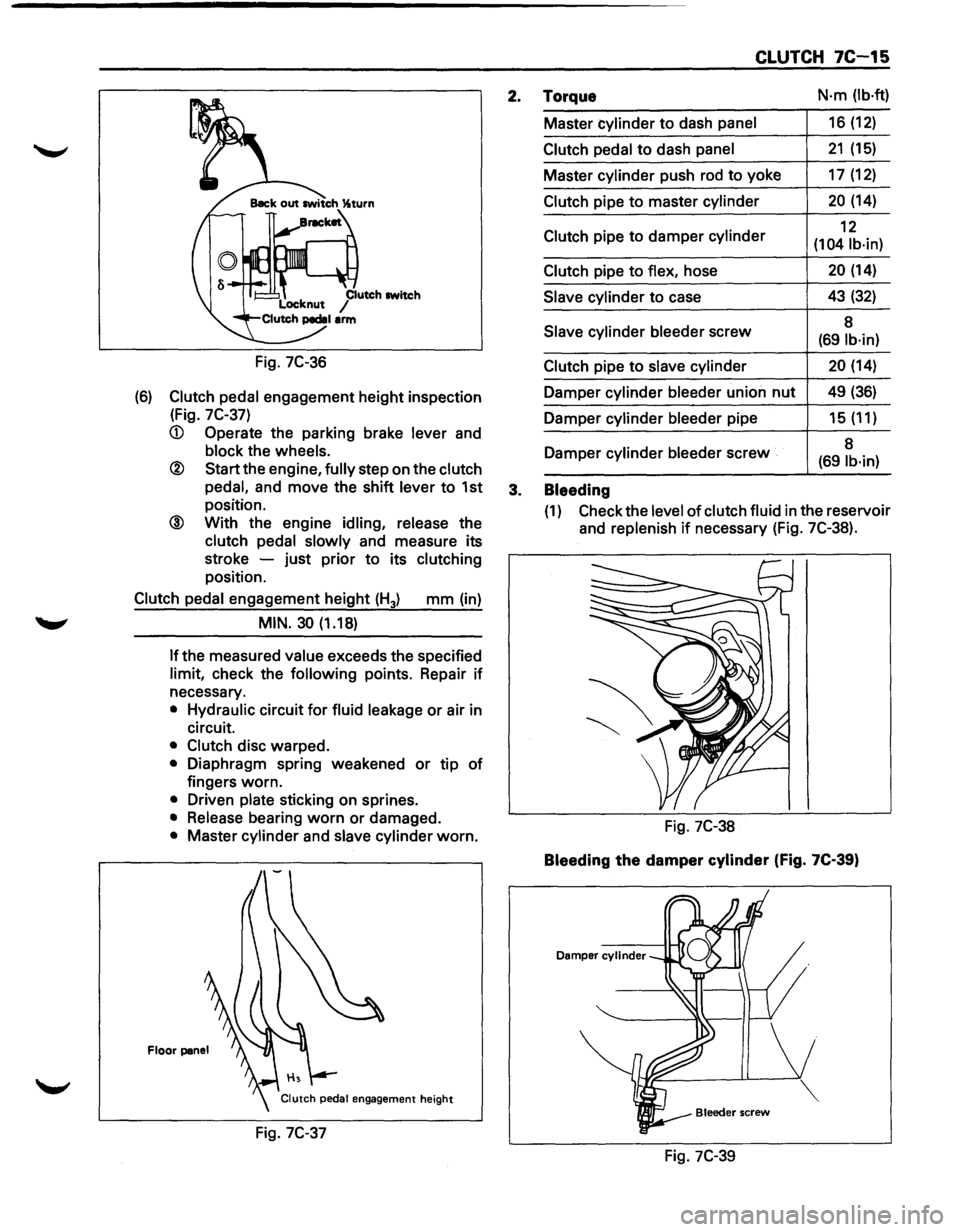
Fig. 7C-36
(6) Clutch pedal engagement height inspection
(Fig.
7C-37)
® Start the engine, fully step on the clutch
pedal,
and move the shift lever to 1st
position.
@ With the engine idling, release the
clutch pedal slowly and measure its
stroke -just prior
to its clutching
position.
Clutch pedal engagement height (H3) mm (in)
MIN. 30 (1.18)
If the
measured value exceeds the specified
limit, check the following points. Repair if
necessary.
• Hydraulic circuit for fluid leakage or air in
circuit.
• Clutch disc warped.
• Diaphragm spring weakened or tip of
fingers worn.
• Driven plate sticking on sprines.
• Release bearing worn or damaged.
• Master cylinder and slave cylinder worn.
Floor panel
Fig. 7C-37
CLUTCH 7C-15
2. Torque N·m (lb·ft)
Master cylinder to dash panel 16 (12)
Clutch pedal to dash panel 21 (15)
Master cylinder push rod to yoke 17 (12)
Clutch pipe to master cylinder 20 (14)
Clutch pipe
to damper cylinder 12
(104 lb·in)
Clutch
pipe to flex, hose 20 (14)
Slave cylinder to case 43 (32)
Slave
cylinder bleeder screw 8 (691b·in)
Clutch
pipe to slave cylinder 20 (14)
Damper cylinder bleeder union nut 49 (36)
Damper cylinder bleeder pipe 15 (11)
Damper cylinder
bleeder screw 8 (69 lb·in)
3. Bleeding
(1) Check
the level of clutch fluid in the reservoir
and
replenish if necessary (Fig. 7C-38).
Fig. 7C-38
Bleeding the damper cylinder (Fig. 7C-39)
Damper cylinder
Fig. 7C-39
Page 1155 of 1928
CLUTCH 7C-21
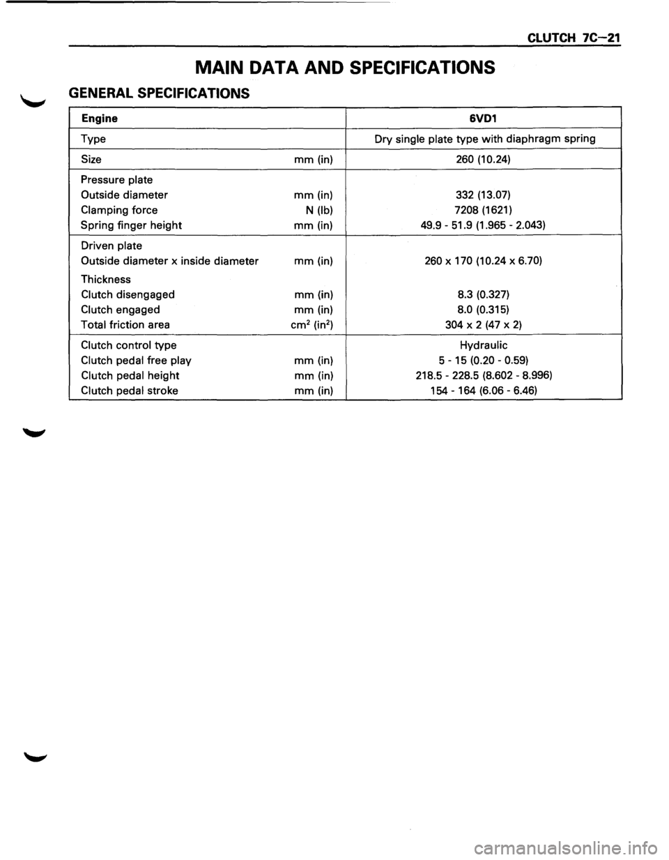
MAIN DATA AND SPECIFICATIONS
GENERAL SPECIFICATIONS
Engine 6VD1
Type Dry single plate type with diaphragm spring
Size mm (in) 260 (10.24)
Pressure plate
Outside
diameter mm (in) 332 (13.07)
Clamping force N (lb) 7208 (1621)
Spring finger height mm (in) 49.9 -51.9 (1.965 -2.043)
Driven plate
Outside
diameter x inside diameter mm (in) 260 X 170 (10.24 X 6.70)
Thickness
Clutch disengaged mm (in) 8.3 (0.327)
Clutch engaged mm (in) 8.0 (0.315)
Total friction area cm2 (in2
) 304 X 2 (47 X 2)
Clutch control type Hydraulic
Clutch pedal
free play mm (in) 5 -15 (0.20 -0.59)
Clutch pedal height mm (in) 218.5 -228.5 (8.602 -8.996)
Clutch pedal stroke mm (in) 154 -164 (6.06 -6.46)