tire type ISUZU TROOPER 1995 User Guide
[x] Cancel search | Manufacturer: ISUZU, Model Year: 1995, Model line: TROOPER, Model: ISUZU TROOPER 1995Pages: 1928
Page 880 of 1928
7 A-8 AUTOMATIC TRANSMISSION (4l30-E)
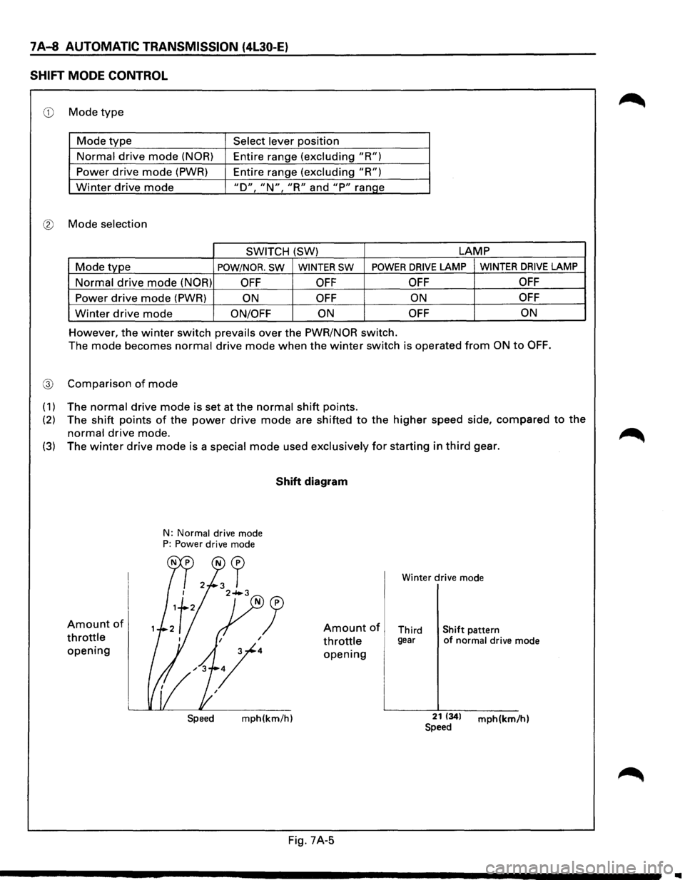
SHIFT MODE CONTROL
CD Mode type
Mode type Select lever position
Normal drive mode (NOR) Entire range (excluding "R")
Power drive mode (PWR) Entire range (excluding "R")
Winter drive mode "D", "N", "R" and "P" range
® Mode selection
SWITCH
(SW) LAMP
Mode type POW/NOR. SW WINTER SW POWER DRIVE LAMP WINTER DRIVE LAMP
Normal drive mode (NOR) OFF OFF
OFF OFF
Power drive mode (PWR) ON OFF ON OFF
Winter drive mode ON/OFF
ON OFF ON
However, the winter switch prevails over
the PWR/NOR switch.
The
mode becomes normal drive mode when the winter switch is operated from ON to OFF.
@ Comparison of mode
(1) The normal drive mode is set at the normal shift points.
(2) The shift points of the power drive mode are shifted to the higher speed side, compared to the
normal drive mode.
(3) The winter drive mode is a special mode used exclusively for starting in third gear.
Amount of
throttle
opening
N: Normal drive mode P: Power drive mode
Shift diagram
Winter drive mode
Amount of Third Shift pattern
throttle gear of normal drive mode
opening
Speed mph(km/h) 21 1341 mph(km/h) Speed
Fig. 7A-5
..
Page 1509 of 1928
![ISUZU TROOPER 1995 User Guide (1!] ON-VEHICLE SERVICE
"-"" Check the meter display accuracy and the operation
of the odometer with the speedometer tester.
\f CAUTION:
Inappropriate tire inflation may affect the accu
rac](/img/61/57183/w960_57183-1508.png "ISUZU TROOPER 1995 User Guide (1!] ON-VEHICLE SERVICE
\"-\"\" Check the meter display accuracy and the operation
of the odometer with the speedometer tester.
\f CAUTION:
Inappropriate tire inflation may affect the accu
rac")
(1!] ON-VEHICLE SERVICE
"-"" Check the meter display accuracy and the operation
of the odometer with the speedometer tester.
\f CAUTION:
Inappropriate tire inflation may affect the accu
racy
of the odometer.
(To
conductthis test, refer to the tester manufac
turer's instruction manual.)
IGN GND
SEN
CHASSIS ELECTRICAL 8-319
(MPH)
Tester display speed Meter
display permissible
level
20 18.3-21.7
40 38.3-41.7
60 58.3-61.7
80 78.8-82.8
100 98.8-102.8
120 118.5-123.1
NOTE: Since the meter display permissible levels
above are specifications solely
for the
meter,
they are to be used as reference
values when conducting on-vehicle service.
~ INDIVIDUAL INSPECTION
I t!!.l Remove the speedometer from the meter
assembly and measure the resistance and the
current consumption between each terminal.
(Fig. 8-347)
Replace the speedometer
when the result of
inspection is found abnormal.
Resistance value
Red(+) Black(-) Black(-) Red(+)
IGN GND IGN GND IGN-GND 00 30.6-37.4k
SEN GND SEN GND SEN-GND 28.8-35.2k 00
4P GND 4P GND 4P-GND 13.5 -16.5k 00
Note: Use the
analog type circuit tester (range: x 1k)
Current value
Terminal
symbol
IGN-GND
~ 8
Current
consumption
85 ± 15mA Remarks
(when
12 ± 1V No signal input
applied)
Note: 1. Use the analog type circuit tester.
2. Since the current consumption fluctuates
when the source voltage varies, check
to
be sure that the voltage applied is 12V ± 1 V.
Fig. 8-347
Page 1646 of 1928
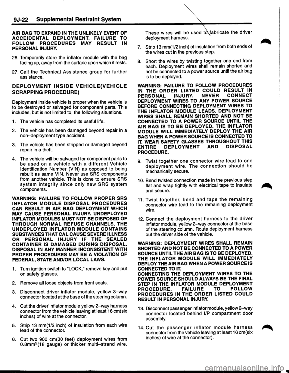
9J-22 Supplemental Restraint System
AIR BAG TO EXPAND IN THE UNLIKELY EVENT OF
ACCEIDENTAL DEPLOYMENT. FAILURE TO
FOLLOW PROCEDURES MAY RESULT IN
PERSONAL INJURY.
26. Temporarily store the inflator module with the bag
facing up, away from the surface upon which it rests.
27.
Call the Technical Assistance group for further
assistance.
DEPLOYMENT INSIDE VEHICLE(VEHICLE
SCRAPPING PROCEDURE)
Deployment inside vehicle is proper when the vehicle is
to be destroyed or
salvaged for component parts. This
includes, but is not limited to, the following situations.
1. The vehicle has completed its useful life.
2. The vehicle has been damaged beyond repair in a
non-deployment type accident.
3. The vehicle has been stripped or damaged beyond
repair
in a theft.
4. The vehicle will be salvaged for component parts to
be
used on a vehicle with a different Vehicle
Identification Number (VIN) as opposed to being
rebuilt as same VIN. Never use SRS components
from another
vehicle. This is done to ensure SRS
system integrity since only new SRS system
components.
WARNING: FAILURE TO FOLLOW PROPER SRS
INFLATOR MODULE DISPOSAL PROCEDURES
CAN RESULT IN AIR BAG DEPLOYMENT WHICH
MAY CAUSE PERSONAL INJURY. UNDEPLOYED
INFLATOR MODULES MUST NOT BE DISPOSED OF
THROUGH NORMAL REFUSE CHANNELS. THE
UNDEPLOYED INFLATOR MODULE CONTAINS
SUBSTANCES THAT CAL CAUSE SEVERE ILLNESS
OR
PERSONAL INJURY IF THE SEALED
CONTAINER IS DAMAGED DURING DISPOSAL.
DISPOSAL IN ANY MANNER INCONSISTENT WITH
PROPER PROCEDURES MAY BE A VIOLATION OF
FEDERAL, STATE AND/OR LOCAL LAWS.
1. Turn ignition switch to "LOCK," remove key and put
on safety glasses.
2. Remove all loose objects from front seats.
3. Disconnect driver inflator module, yellow 3-way
connector located at the base of the steering column.
4. Cut the driver inflator module yellow 2-way harness
connector from the
vehicle leaving at least 16 cm(six
inches) of wire at the connector.
5. Strip 13 mm(1/2 inch) of insulation from each wire
lead of the connector.
6. Cut two 900 cm(30 feet) deployment wires from
0.8mm2(18 gauge) or thicker
multi-strand wire. These
wires
will be used to fabricate the driver
deployment harness.
7. Strip 13 mm(1/2 inch) of insulation from both ends of
the wires cut
in the previous step.
8. Short the wires by twisting together one end from
each. Deployment wires
shall remain shorted and
not
be connected to a power source until the air bag
is to be
deployed.
WARNING: FAILURE TO
FOLLOW PROCEDURES
IN
THE ORDER LISTED COULD RESULT IN
PERSONAL INJURY. NEVER CONNECT
DEPLOYMENT WIRES TO ANY POWER SOURCE
BEFORE CONNECTING DEPLOYMENT WIRES TO
THE INFLATOR MODULE LEADS. DEPLOYMENT
WIRES SHALL REMAIN SHORTED AND NOT BE
CONNECTED TO A POWER SOURCE UNTIL THE
AIR BAG IS TO BE DEPLOYED. THE INFLATOR
MODULE WILL IMMEDIATELY DEPLOY THE AIR
BAG WHEN A POWER SOURCE IS CONNECTED TO
IT. WEAR SAFETY GLASSES THROUGHOUT THIS
ENTIRE DEPLOYMENT AND DISPOSAL
PROCEDURE.
9. Twist together one connector wire lead to one
deployment wire. The connection should be
mechanically secure.
10. Bend twisted connection made in the previous step
flat and wrap tightly with electrical tape to insulate ~
and secure.
11. Twist together, bend and tape the remaining
connector wire lead to the remaining deployment
wire.
12. Connect the deployment harness to the driver
inflator module, yellow 2-way connector at the base
of the steering
column. Route deployment harness
out the driver side of the
vehicle.
WARNING:
DEPLOYMENT WIRES SHALL REMAIN
SHORTED
AND NOT BE CONNECTED TO A POWER
SOURCE UNTIL THE AIR BAG IS TO BE DEPLOYED.
THE INFLATOR MODULE WILL IMMEDIATELY
DEPLOY THE AIR BAG WHEN A POWER SOURCE IS
CONNECTED TO IT.
CONNECTING THE DEPLOYMENT WIRES TO THE
POWER
SOURCE SHOULD ALWAYS BE THE FINAL
STEP IN
THE INFLATOR MODULE DEPLOYMENT
PROCEDURE. FAILURE TO FOLLOW
PROCEDURES IN THE ORDER LISTED COULD
RESULT IN PERSONAL INJURY.
13. Disconnect passenger inflator module, yellow 2-way
connector located behind 1/P compartment door
assembly.
14. Cut the passenger inflator module harness
connector from the vehicle leaving at least 16 cm(six
inches) of wire at the connector).