OBD port ISUZU TROOPER 1995 Workshop Manual
[x] Cancel search | Manufacturer: ISUZU, Model Year: 1995, Model line: TROOPER, Model: ISUZU TROOPER 1995Pages: 1928
Page 706 of 1928
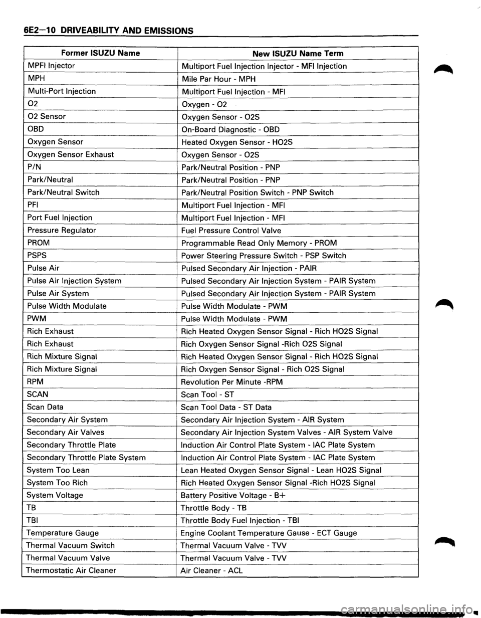
6E2-10 DRIVEABILITY AND EMISSIONS
Former ISUZU Name New ISUZU Name Term
MPFI Injector Multiport Fuel Injection Injector -MFI Injection
MPH Mile Par Hour -MPH
Multi-Port Injection
Multiport Fuel Injection -MFI
02 Oxygen-02
02 Sensor Oxygen Sensor -02S
OBD On-Board Diagnostic -OBD
Oxygen Sensor
Heated Oxygen Sensor -H02S
Oxygen
Sensor Exhaust Oxygen Sensor -02S
P/N
Park/Neutral Position -PNP
Park/Neutral
Park/Neutral Position -PNP
Park/Neutral Switch Park/Neutral Position Switch -PNP Switch
PFI Multiport Fuel Injection -MFI
Port Fuel Injection Multiport Fuel Injection -MFI
Pressure Regulator
Fuel Pressure Control Valve
PROM Programmable Read Only Memory -PROM
PSPS Power Steering Pressure Switch-PSP Switch
Pulse Air Pulsed Secondary Air Injection -PAIR
Pulse Air Injection System Pulsed Secondary Air Injection System -PAIR System
Pulse Air System Pulsed Secondary Air Injection System -PAIR System
Pulse Width Modulate Pulse Width Modulate -PWM
PWM Pulse
Width Modulate -PWM
Rich Exhaust
Rich Heated Oxygen Sensor Signal -Rich H02S Signal
Rich Exhaust
Rich Oxygen Sensor Signal -Rich 02S Signal
Rich Mixture Signal Rich Heated Oxygen Sensor Signal -Rich H02S Signal
Rich Mixture Signal Rich Oxygen Sensor Signal -Rich 02S Signal
RPM Revolution Per Minute -RPM
SCAN
Scan Tool -ST
Scan Data Scan Tool Data -ST Data
Secondary
Air System Secondary Air Injection System -AIR System
Secondary
Air Valves Secondary Air Injection System Valves -AIR System Valve
Secondary Throttle Plate
Induction Air Control Plate System -lAC Plate System
Secondary Throttle
Plate System Induction Air Control Plate System -lAC Plate System
System Too Lean
Lean Heated
Oxygen Sensor Signal -Lean H02S Signal
System Too Rich
Rich Heated Oxygen Sensor Signal -Rich H02S Signal
System Voltage Battery Positive Voltage -B+
TB Throttle Body -TB
TBI Throttle Body Fuel Injection -TBI
Temperature Gauge
Engine Coolant Temperature Gause -ECT Gauge
Thermal Vacuum Switch
Thermal Vacuum
Valve -TVV
Thermal Vacuum Valve Thermal Vacuum Valve -TVV
Thermostatic Air Cleaner Air Cleaner -ACL
Page 730 of 1928
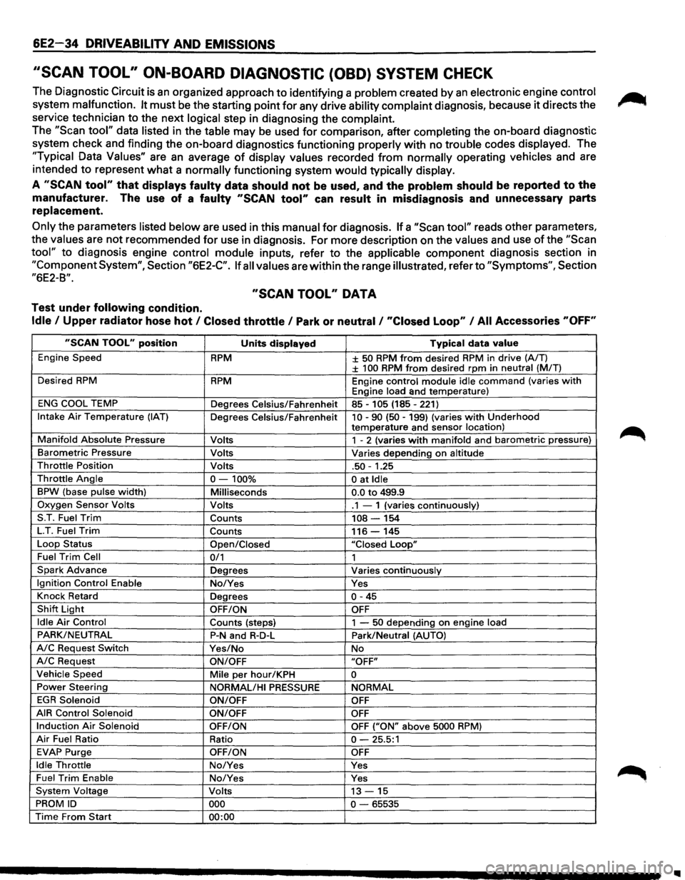
6E2-34 DRIVEABILITY AND EMISSIONS
''SCAN TOOL" ON-BOARD DIAGNOSTIC (OBD) SYSTEM CHECK
The Diagnostic Circuit is an organized approach to identifying a problem created by an electronic engine control
system malfunction. It must be the starting point for any drive ability complaint diagnosis, because it directs the
service technician to the next
logical step in diagnosing the complaint.
The "Scan tool" data listed in the table may be used for comparison, after completing the on-board diagnostic
system check and finding the on-board diagnostics functioning
properly with no trouble codes displayed. The
"Typical Data Values" are an average of display values recorded from normally operating vehicles and are
intended
to represent what a normally functioning system would typically display.
A "SCAN tool" that displays faulty data should not be used, and the problem should be reported to the
manufacturer. The use of a faulty "SCAN tool" can result in misdiagnosis and unnecessary parts
replacement.
Only the parameters listed below are used in this manual for diagnosis. If a "Scan tool" reads other parameters,
the
values are not recommended for use in diagnosis. For more description on the values and use of the "Scan
tool" to diagnosis engine control module inputs, refer to the applicable component diagnosis section in
"Component System", Section "6E2-C". If all values are within the range illustrated, refer to "Symptoms", Section
"6E2-B".
"SCAN TOOL" DATA
Test under following condition.
Idle I Upper radiator hose hot I Closed throttle I Park or neutral I "Closed Loop" I All Accessories "OFF"
"SCAN TOOL" position Units displayed Typical data value
Engine Speed RPM ± 50 RPM from desired RPM in drive (A/T) ± 100 RPM from desired rpm in neutral (MIT)
Desired
RPM RPM Engine control module idle command (varies with Engine load and temperature)
ENG COOL TEMP
Degrees Celsius/Fahrenheit 85-105 (185-221)
Intake Air Temperature (IAT) Degrees Celsius/Fahrenheit 10-90 (50-199) (varies with Underhood
temperature and sensor location)
Manifold Absolute Pressure Volts 1 - 2 (varies with manifold and barometric pressure)
Barometric Pressure Volts Varies depending on altitude
Throttle Position Volts .50-1.25
Throttle Angle 0-100% 0 at Idle
BPW (base pulse width) Milliseconds 0.0 to 499.9
Oxygen Sensor Volts Volts .1 - 1 (varies continuously)
S.T. Fuel
Trim Counts 108-154
LT. Fuel Trim Counts 116-145
Loop Status
Open/Closed "Closed Loop"
Fuel Trim Cell 0/1 1
Spark Advance Degrees Varies continuously
Ignition Control Enable No/Yes Yes
Knock Retard
Degrees
0-45
Shift Light OFF/ON OFF
Idle Air Control
Counts (steps) 1 -50 depending on engine load
PARK/NEUTRAL P-N and R-D-L Park/Neutral (AUTO)
A/C Request Switch Yes/No No
A/C Request ON/OFF "OFF"
Vehicle Speed
Mile per hour/KPH 0
Power Steering
NORMAL/HI PRESSURE NORMAL
EGR Solenoid
ON/OFF OFF
AIR Control Solenoid
ON/OFF OFF
Induction Air Solenoid OFF/ON OFF ("ON" above 5000 RPM)
Air Fuel Ratio Ratio 0-25.5:1
EVAP Purge OFF/ON OFF
Idle Throttle No/Yes Yes
Fuel Trim Enable No/Yes Yes
System Voltage Volts 13-15
PROM ID 000 0-65535
Time From Start 00:00