wheel alignment ISUZU TROOPER 1995 User Guide
[x] Cancel search | Manufacturer: ISUZU, Model Year: 1995, Model line: TROOPER, Model: ISUZU TROOPER 1995Pages: 1928
Page 134 of 1928
3A-2 FRONT END ALIGNMENT
DEFINITION OF TERMS
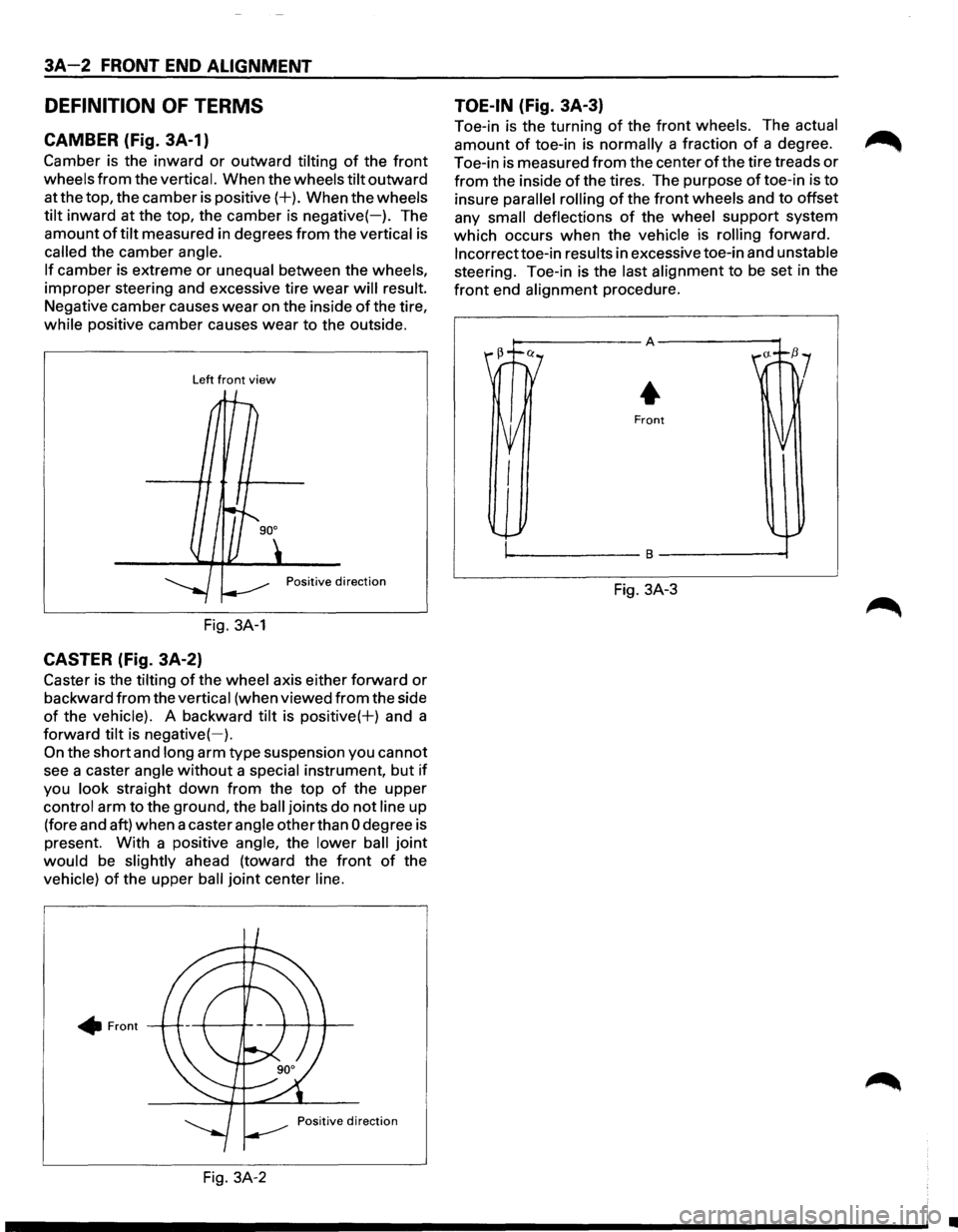
CAMBER (Fig. 3A-1)
Camber is the inward or outward tilting of the front
wheels from the vertical. When the wheels tilt outward
at the top, the camber is
positive(+). When the wheels
tilt inward at the top, the camber is negative(-). The
amount
of tilt measured in degrees from the vertical is
called the camber angle.
If camber is extreme or unequal between the wheels,
improper steering and excessive tire
wear will result.
Negative camber causes
wear on the inside of the tire,
while positive camber causes wear to the outside.
Left front view
Positive direction
Fig. 3A-1
CASTER (Fig. 3A-2)
Caster is the tilting of the wheel axis either forward or
backward from the vertical (when viewed from the side
of the vehicle). A backward tilt is positive(+) and a
forward tilt is
negative(-).
On the short and long arm type suspension you cannot
see a caster angle
without a special instrument, but if
you look straight down from the top of the upper
control arm to the ground, the
ball joints do not line up
(fore and aft) when a caster angle other than
0 degree is
present. With a positive angle, the lower
ball joint
would be slightly ahead (toward the front of the
vehicle)
of the upper ball joint center line .
• Front
Fig. 3A-2
TOE-IN (Fig. 3A-3)
Toe-in is the turning of the front wheels. The actual
amount of toe-in is normally a fraction of a degree.
Toe-in is measured
from the center of the tire treads or
from the inside of the tires. The purpose of toe-in is to
insure
parallel rolling of the front wheels and to offset
any
small deflections of the wheel support system
which occurs
when the vehicle is rolling forward.
lncorrecttoe-in results in excessive toe-in and unstable
steering. Toe-in is the last alignment to
be set in the
front end alignment procedure.
Fig. 3A-3
•
Page 135 of 1928
FRONT END ALIGNMENT 3A-3
ON-VEHICLE SERVICE
INSPECTION
Before making any adjustments affecting caster,
camber or toe-in, the following front end inspection
should be made.
I L•IINSPECT
1. Tires for proper inflation pressure. Refer to
"Wheels and Tires" in section 3E.
2. Front wheel bearings for proper adjustment.
Refer to "Front Wheel Drive" in section 4C.
3. Ball joints, tie rod ends and relay rods. If
excessive looseness is noted, correct before
adjusting. Refer
to "Steering Linkage" in section
3B3.
4. Wheel and tires for run-out. Refer to "Wheels
and Tires" in section 3E.
5. Trim height. If not within specifications, the
correction
must be made before adjusting caster.
6. Steering gear for looseness at the frame.
7. Shock absorbers for leaks or any noticeable
noise.
Refer
to "Front Suspension" in section 3C.
8. Control arms or stabilizer bar attachment for
looseness. Refer to "Front Suspension" in section
3C.
9. Alignment equipment. Follow the manufacturer's
instructions.
10. Level of the vehicle. The vehicle must be on a
level surface.
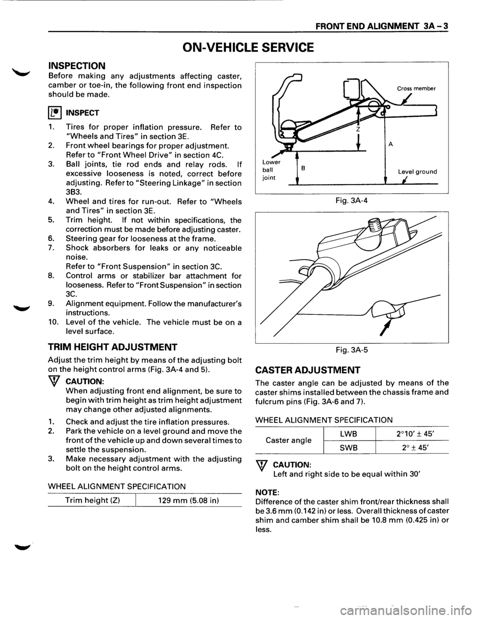
TRIM HEIGHT ADJUSTMENT
Adjust the trim height by means of the adjusting bolt
on the height control arms (Fig. 3A-4 and 5).
W CAUTION:
When adjusting front end alignment, be sure to
begin with trim height as trim height adjustment
may change other adjusted alignments.
1. Check and adjust the tire inflation pressures.
2. Park the vehicle on a level ground and move the
front of the vehicle up and down several times to
settle the suspension.
3. Make necessary adjustment with the adjusting
bolt on the height control arms.
WHEEL
ALIGNMENT SPECIFICATION
Trim height (Z) 129 mm (5.08 in)
Lower
ball joint
B
Fig. 3A-4
Fig. 3A-5
CASTER ADJUSTMENT
Level ground
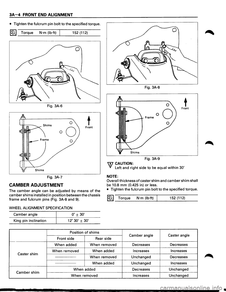
The caster angle can be adjusted by means of the
caster shims installed between the chassis frame and
fulcrum pins (Fig. 3A-6 and 7).
WHEEL
ALIGNMENT SPECIFICATION
LWB
Caster angle
SWB
W CAUTION:
Left and right side to be equal within 30'
NOTE:
Difference of the caster shim front/rear thickness shall
be 3.6
mm (0.142 in) or less. Overall thickness of caster
shim and camber shim shall be 10.8 mm (0.425 in) or
less.
Page 136 of 1928
3A-4 FRONT END ALIGNMENT
• Tighten the fulcrum pin bolt to the specified torque.
1~1 Torque N·m (lb·ft) 152 (112)
Fig. 3A-6
0 t Front
0
Fig. 3A-8
Fig. 3A-9
\fl CAUTION:
t Front
'(/ Left and right side to be equal within 30'
NOTE:
Fig. 3A-7
CAMBER ADJUSTMENT
Overall thickness of caster shim and camber shim shall
be 10.8 mm (0.425 in) or less.
The camber angle can be adjusted by means of the
camber shims
installed in position between the chassis
frame and
fulcrum pins (Fig. 3A-8 and 9).
• Tighten the fulcrum pin bolt to the specified torque.
~~~ Torque N·m (lb·ft) 152 (112)
WHEEL ALIGNMENT SPECIFICATION
Camber angle o· ± 30'
King pin inclination 12° 30' ± 30'
Position of shims
Front side Rear
side Camber angle Caster angle
1---When
added When
removed Decreases Decreases
When removed When
added
Increases Increases Caster shim
When removed Unchanged Decreases
When added Unchanged
Increases
When added Decreases
Unchanged
Camber shim
When removed
Increases Unchanged
Page 137 of 1928
TOE-IN ADJUSTMENT
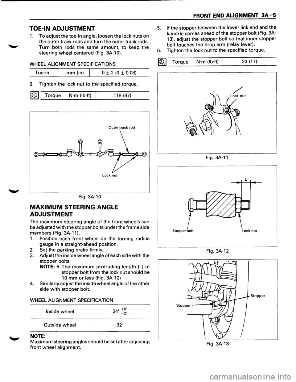
1. To adjust the toe-in angle, loosen the lock nuts on
the outer track rods and turn the outer track rods.
Turn both rods the same amount, to keep the
steering
wheel centered (Fig. 3A-1 0).
WHEEL ALIGNMENT SPECIFICATIONS
Toe-in mm (in) I 0 ± 2 (0 ± 0.08)
2. Tighten the lock nut to the specified torque.
~~~ Torque N·m (lb·ft) 118 (87)
Outer track rod
Lock nut
Fig. 3A-10
MAXIMUM STEERING ANGLE
ADJUSTMENT
The maximum steering angle of the front wheels can
be adjusted
with the stopper bolts under the frame side
members (Fig. 3A-11 ).
1. Position each front wheel on the turning radius
gauge in a straight-ahead position.
2. Set the parking brake firmly.
3. Adjust the inside wheel angle of each side with the
stopper
bolts.
NOTE: • The maximum protruding length (L) of
stopper bolt from the lock nut should be
10 mm or less (Fig. 3A-12)
4. Similarly adjust the inside wheel angle of the other
side
with stopper bolt.
WHEEL ALIGNMENT SPECIFICATION
Inside wheel
34° ~~:
Outside wheel 32°
NOTE:
Maximum steering angles should be set after adjusting
front wheel alignment.
FRONT END ALIGNMENT 3A-5
5. If the stopper between the lower link end and the
knuckle comes ahead of the stopper bolt (Fig. 3A-
13), adjust the stopper
bolt so that inner stopper
bolt touches the drop arm (relay lever).
6. Tighten the lock nut to the specified torque.
~~~ Torque N·m (lb·ft) 23 (17)
Fig. 3A-11
L
Stopper bolt Lock nut
Fig. 3A-12
Stopper
Fig. 3A-13
Page 157 of 1928
STEERING LINKAGE 383-1
SECTION 383
STEERING LINKAGE
w CAUTION:
• When fasteners are removed, always reinstall them at the same location from which they were removed. If a
fastener needs
to be replaced, use the correct part number fastener for that application. If the correct part
number fastener is not available, a fastener of equal size and strength (or stronger) may be used. Fasteners
that are not reused, and those requiring thread locking compound, will be called out. The correct torque
value must be used when installing fasteners that require it. If the above conditions are not followed, parts or
system damage could result.
CONTENTS
General Description . . . . . . . . . . . . . . . . . . . . 383-1
On-Vehicle Service .................... 383-2
Center Track Rod Assembly . . . . . . . . . . . 383-2
Outer Track Rod Assembly . . . . . . . . . . . . 383-4
Relay Lever . . . . . . . . . . . . . . . . . . . . . . . . . 383-6 Main
Data
and Specifications ............ 383-8
Torque Specifications
................ 383-8
Special Tools .......................... 383-8
GENERAL DESCRIPTION
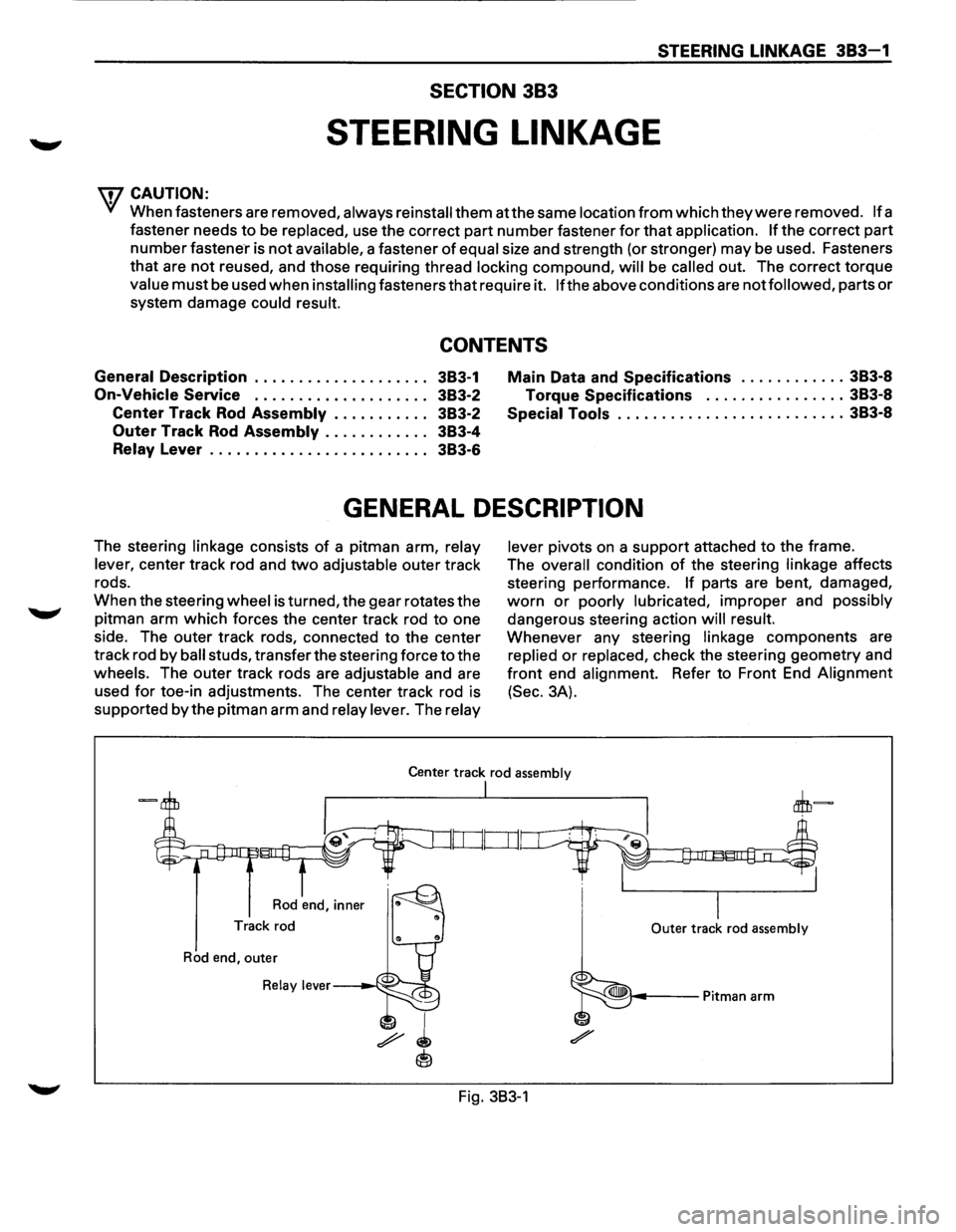
The steering linkage consists of a pitman arm, relay
lever,
center track rod and two adjustable outer track
rods.
When the steering
wheel is turned, the gear rotates the
pitman arm
which forces the center track rod to one
side. The outer track rods, connected to the center
track rod
by ball studs, transfer the steering force to the
wheels. The outer track rods are adjustable and are
used
for toe-in adjustments. The center track rod is
supported
by the pitman arm and relay lever. The relay lever
pivots
on a support attached to the frame.
The
overall condition of the steering linkage affects
steering performance.
If parts are bent, damaged,
worn or poorly lubricated, improper and possibly
dangerous steering action will result.
Whenever any steering linkage components are
replied or replaced, check the steering geometry and
front end alignment. Refer to Front End Alignment
(Sec. 3A).
Center track rod assembly
Rod end, inner
Track rod
Rod end, outer
Relay lever---~·--:;:::jo
I
I Outer track rod assembly
Fig. 383-1
Page 165 of 1928
FRONT SUSPENSION 3C-1
SECTION 3C
FRONT SUSPENSION
'\f CAUTION:
When fasteners are removed, always reinstall them at the same location from which they were removed.
If a fastener needs to be replaced, use the correct part number fastener for that application. If the correct
part
number fastener is not available, a fastener of equal size and strength (or stronger) may be used.
Fasteners
that are not reused, and those requiring thread locking compound, will be called out. The correct
torque value must be used when installing fasteners that require it. If the above conditions are not
followed, parts or system damage could result.
Refer to section 3A in this manual for the wheel alignment procedure.
CONTENTS
General Description .. .. .. .. .. .. .. .. .. .. .. .. .. .. . 3C- 1
On-Vehicle Service .............................. 3C-3
Shock Absorber . . . . . . . . . . . . . . . . . . . . . . . . . . . . . . . 3C-3
Stabilizer Bar . .. .. . .. .. ..
.. . .. .. . .. .. .. . .. .. .. . 3C- 4
Torsion Bar
.................................... 3C-5
Knuckle . .
. . . . . . . . . . . . . . . . . . . . . . . . . . . . . . . . . . . . . . 3C-7
Upper
Control Arm ........................... 3C-10
Lower Control Arm ........................... 3C-13
Upper Ball Joint ............................... 3C- 16
Lower
Ball Joint ............................... 3C-18
Main Data and Specifications.................. 3C-20
General
Specifications . .
. . . . . . . . . . . . . . . . . . . . . 3C-
20
Torque Specifications ........................ 3C-21
Special Tools ..................................... 3C-22
GENERAL DESCRIPTION
The front suspension is designed to allow each wheel
to compensate for changes in the road surface level
without greatly affecting the opposite wheel. Each
wheel is independently connected to the frame by a
steering
knuckle, ball joint assemblies, and upper and
lower control arms. The front wheels are held in
proper relationship to each other by two outer track
rods
which are connected to steering arms on the
knuckles and to a center track rod.
All models have a front suspension system consisting
of control arms, stabilizer bar, shock absorber and a
torsion bar. The front end of the torsion bar is
attached
to the lower control arm. The rear of the
torsion bar is mounted into a height control arm at the
crossmember. Vehicle trim height is controlled by
adjusting this arm.
Shock absorbers are
mounted between the brackets
on the
frame and the lower control arms. The lower
portion of each shock absorber is attached to the
lower control arm by a bolt and nut. The upper portion
of each shock absorber extends through a frame
bracket and is secured with two rubber bushings,
three retainers and a nut.
Ball joint assemblies are bolted to the outer end of the
upper and lower control arm and are attached to the
steering
knuckle by nuts and cotter pins.
The
inner ends of the upper control arm have pressed
in bushings.
Bolts, passing through the bushing,
attach the control arm to the frame. The inner ends of
the lower control arm are attached to the frame by
bolts passing through the bushings, which are
pressed in the frame.
Side
roll of the front suspension is controlled by a
spring steel stabilizer bar. It is mounted in rubber
bushings, which are held to the crossmember by
brackets. The ends of the stabilizer bar are connected
to the lower control arms by links.
Page 202 of 1928
3E-2 WHEELS AND TIRES
DIAGNOSIS
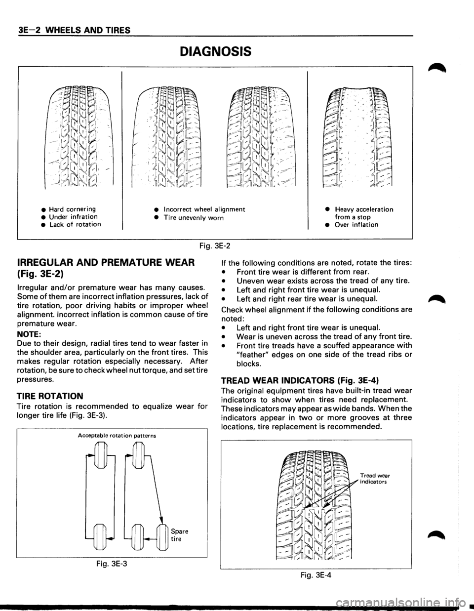
• Hard cornering • Incorrect wheel alignment
• Heavy acceleration from a stop • Under infration • Tire unevenly worn • Lack of rotation • Over inflation
Fig. 3E-2
IRREGULAR AND PREMATURE WEAR
(Fig. 3E-2)
Irregular and/or premature wear has many causes.
Some of them are incorrect inflation pressures, lack of
tire rotation, poor driving habits or improper wheel
alignment. Incorrect inflation
is common cause of tire
premature wear.
NOTE:
Due to their design, radial tires tend to wear faster in
the
shoulder area, particularly on the front tires. This
makes
regular rotation especially necessary. After
rotation, be sure to check wheel nut torque, and set tire
pressures.
TIRE ROTATION
Tire rotation is recommended to equalize wear for
longer tire life (Fig. 3E-3).
Acceptable rotation patterns
Fig. 3E-3
Spare tire
If the following conditions are noted, rotate the tires:
• Front tire wear is different from rear.
• Uneven wear exists across the tread of any tire.
• Left and right front tire wear is unequal.
•
Left and right rear tire wear is unequal.
Check wheel alignment if the following conditions are
noted:
• Left and right front tire wear is unequal.
•
Wear is uneven across the tread of any front tire.
• Front tire treads have a scuffed appearance with
"feather" edges on one side of the tread ribs or
blocks.
TREAD WEAR INDICATORS (fig. 3E-4)
The original equipment tires have built-in tread wear
indicators to show when tires need replacement.
These indicators may appear as wide bands. When the
indicators appear in
two or more grooves at three
locations, tire replacement is recommended.
Fig. 3E-4
Tread wear
indicators
•
Page 203 of 1928
INFLATION OF TIRES
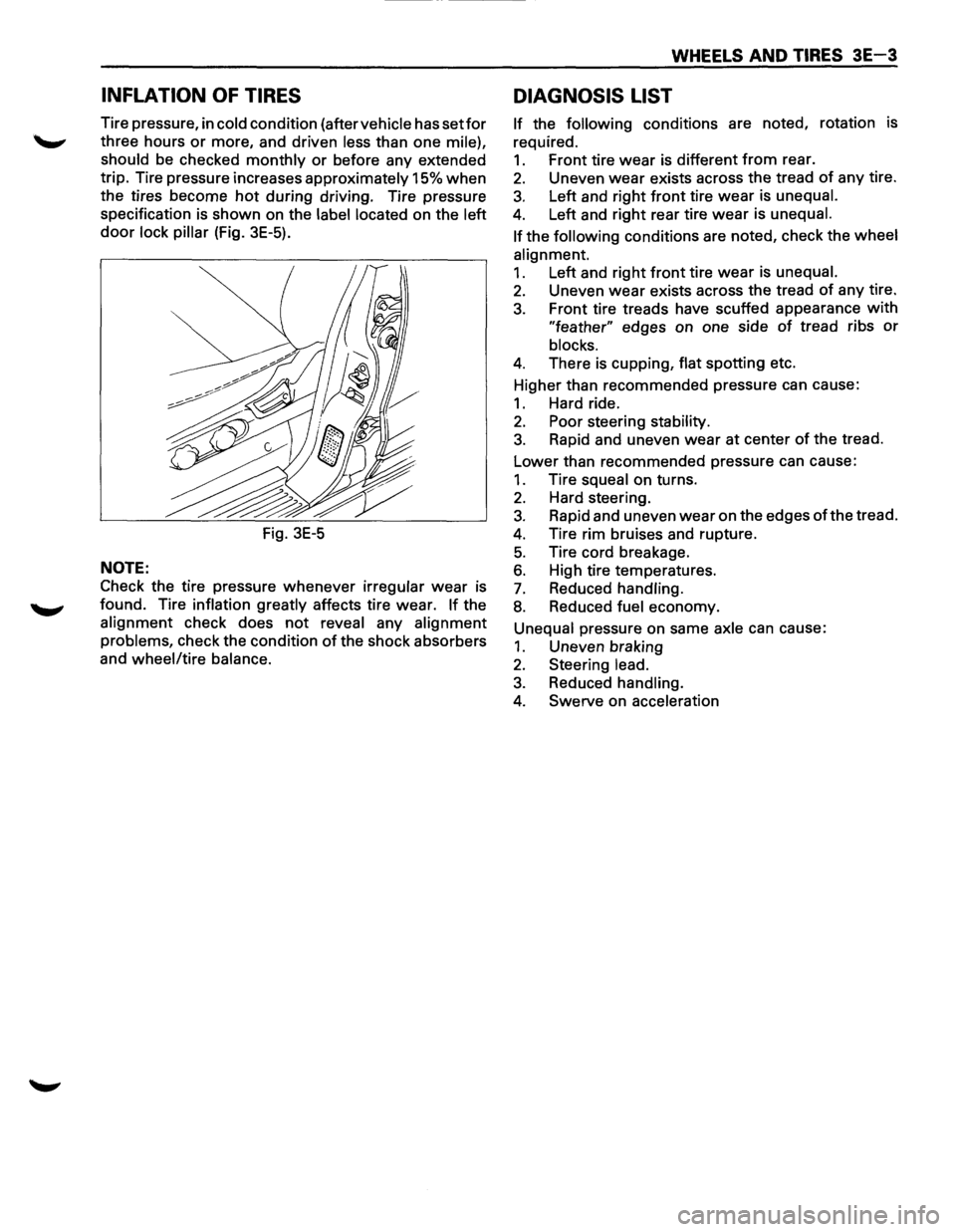
Tire pressure, in cold condition (after vehicle has setfor
three hours or more, and driven less than one mile),
should
be checked monthly or before any extended
trip. Tire pressure increases
approximately 15% when
the tires become hot during driving. Tire pressure
specification is shown on the
label located on the left
door lock pillar (Fig. 3E-5).
Fig.
3E-5
NOTE:
Check the tire pressure whenever irregular wear is
found. Tire
inflation greatly affects tire wear. If the
alignment check does not reveal any alignment
problems,
check the condition of the shock absorbers
and
wheel/tire balance.
WHEELS AND TIRES 3E-3
DIAGNOSIS LIST
If the following conditions are noted, rotation is
required.
1. Front tire wear is different from rear.
2. Uneven wear exists across the tread of any tire.
3. Left and right front tire wear is unequal.
4. Left and right rear tire wear is unequal.
If
the following conditions are noted, check the wheel
alignment.
1. Left and right front tire wear is unequal.
2. Uneven wear exists across the tread of any tire.
3. Front tire treads have scuffed appearance with
"feather" edges on one side of tread ribs or
blocks.
4. There is cupping, flat spotting etc.
Higher than recommended pressure can cause:
1. Hard ride.
2. Poor steering stability.
3. Rapid and uneven wear at center of the tread.
Lower than recommended pressure can cause:
1. Tire squeal on turns.
2. Hard steering.
3. Rapid and uneven wear on the edges of the tread.
4. Tire rim bruises and rupture.
5. Tire cord breakage.
6. High tire temperatures.
7. Reduced handling.
8. Reduced fuel economy.
Unequal pressure on same axle can cause:
1. Uneven braking
2. Steering lead.
3. Reduced handling.
4. Swerve on acceleration
Page 204 of 1928
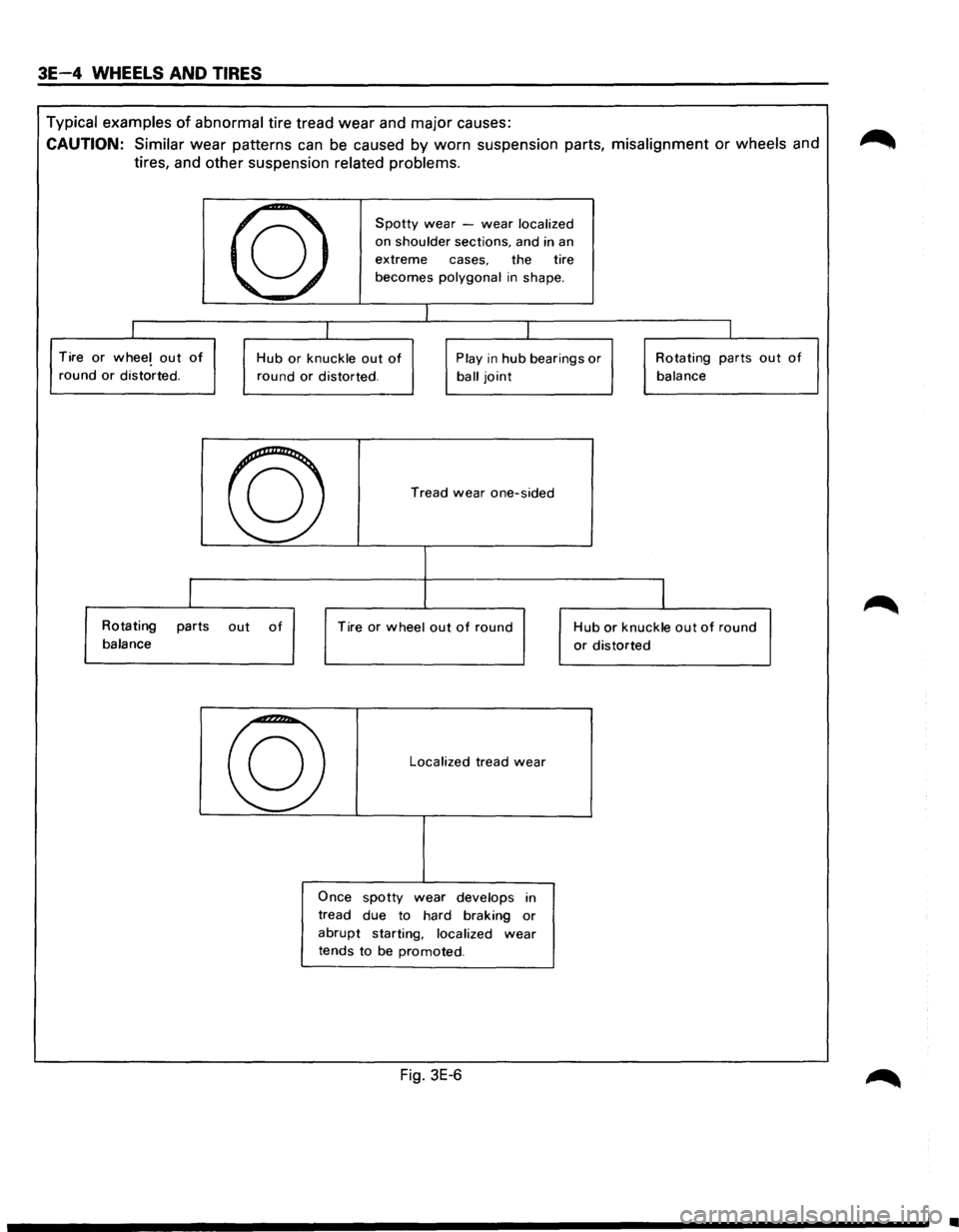
3E-4 WHEELS AND TIRES
Typical examples of abnormal tire tread wear and major causes:
CAUTION: Similar wear patterns can be caused by worn suspension parts, misalignment or wheels and
tires, and other suspension
related problems.
I
Tire or wheel out of
round or distorted.
I
Rotating parts
balance
-
10
Spotty wear -wear localized
, on shoulder sections, and in an
extreme cases. the tire
'
becomes polygonal in shape.
I
I I
I
Hub or knuckle out of Play in hub bearings or Rotating parts
round or distorted.
ball joint
-
ro
out of
Tread wear one-sided
Tire or wheel out of round
Localized tread wear
Once spotty wear develops in
tread due to hard braking
or
abrupt starting, localized wear
tends to be promoted.
Fig. 3E-6
balance
I
Hub or knuckle out of round
or distorted
out of
•
Page 219 of 1928
SUPPLEMENTAL RESTRAINT SYSTEM (SRS) STEERING WHEEL & COLUMN 3F4-9
B INSTALLATION
6. Combination switch and SRS coil assembly
•
After installation of combination switch as
sembly, connect the combination switch
wiring harness connector and the SRS 3way
connector located under the steering column.
•
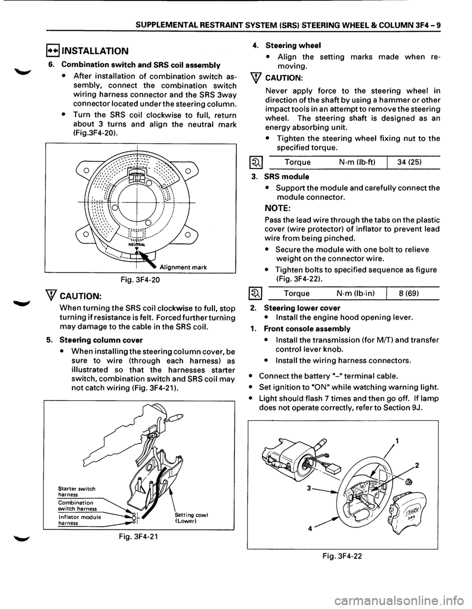
Turn the SRS coil clockwise to full, return
about 3
turns and align the neutral mark
(Fig.3F4-20).
Alignment mark
Fig. 3F4-20
WcAUTION:
When turning the SRS coil clockwise to full, stop
turning if resistance is felt. Forced further turning
may damage to the cable in the SRS coil.
5. Steering column cover
• When installing the steering column cover, be
sure
to wire (through each harness) as
illustrated so that the harnesses starter
switch,
combination switch and SRS coil may
not catch wiring (Fig. 3F4-21 ).
Starter switch
harness
Combination switch harness
Inflator module harness
Fig. 3F4-21
4. Steering wheel
• Align the setting marks made when re
moving.
W CAUTION:
Never apply force to the steering wheel in
direction
of the shaft by using a hammer or other
impact tools in an attempt to remove the steering
wheel. The steering shaft is designed as an
energy absorbing unit.
• Tighten the steering wheel fixing nut to the
specified torque.
Torque
N·m (lb-ft) 34 (25)
3. SRS module
• Support the module and carefully connect the
module connector.
NOTE:
Pass the lead wire through the tabs on the plastic
cover (wire protector) of inflator to prevent lead
wire from being pinched.
• Secure the module with one bolt to relieve
weight on the connector wire.
• Tighten bolts to specified sequence as figure
(Fig. 3F4-22).
Torque
N·m (lb·in) 8 (69)
2. Steering lower cover
• Install the engine hood opening lever.
1. Front console assembly
• Install
the transmission (for MfT) and transfer
control lever knob.
• Install the wiring harness connectors.
• Connect the battery "-"terminal cable.
• Set
ignition to ·oN" while watching warning light.
•
Light should flash 7 times and then go off. If lamp
does not operate correctly, refer to Section 9J.
Fig. 3F4-22