stop start ISUZU TROOPER 1995 Workshop Manual
[x] Cancel search | Manufacturer: ISUZU, Model Year: 1995, Model line: TROOPER, Model: ISUZU TROOPER 1995Pages: 1928
Page 57 of 1928
The refrigeration cycle includes the following four
processes as the refrigerant changes repeatedly
from liquid to gas and back to liquid while circulat
ing.
EVAPORATION
The refrigerant is changed from a liquid to a gas in
side
the evaporator. The refrigerant mist that enters
the evaporator vaporizes readily. The liquid refrige
rant removes
the required quantity of heat (latent
heat of vaporization) from the air around the evap
orator core cooling fins and rapidly vaporizes.
Removing the heat cools the air, which is then
radiated
from the fins and lowers the temperature of
the air inside the vehicle.
The refrigerant liquid sent from the expansion valve
and the vaporized refrigerant gas are both present
inside the
evaporator and the liquid is converted to
gas.
With this change from liquid to gas, the pressure
inside
the evaporator must be kept low enough for
vaporization to occur at a lower temperature.
Because of that, the vaporized refrigerant is sucked
into the compressor.
COMPRESSION
The refrigerant is compressed by the compressor
until it is easily liquefied at normal temperature.
The vaporized
refrigerant in the evaporator is sucked
into the compressor. This action maintains the
refrigerant inside the evaporator at a low pressure
so
that it can easily vaporize, even at low tempera
tures close to ooc (32°F).
Also, the refrigerant sucked into the compressor is
compressed inside the
cylinder to increase the
pressure and temperature to values such that the
refrigerant can easily liquefy at normal ambient
temperatures.
CONDENSATION
The refrigerant inside the condenser is cooled by the
outside air and changes from gas to liquid.
The high temperature, high pressure gas coming
from the compressor is cooled and liquefied by the
condenser with outside air and accumulated in the
receiver/drier. The heat radiated to the outside air by
the high temperature, high pressure gas in the
compressor is called heat of condensation. This is
the total quantity of heat (heat of vaporization) the
refrigerant removes
from the vehicle interior via the
evaporator and the work (calculated as the quantity
of heat) performed for compression.
'-' EXPANSION
The expansion valve lowers the pressure of the
refrigerant liquid so that it can easily vaporize.
AIR CONDITIONING 1 B -3
The process of lowering the pressure to encourage
vaporization before the
liquefied refrigerant is sent
to the evaporator is called expansion. In addition,
the expansion valve controls the flow rate of the
refrigerant liquid while decreasing the pressure.
That is, the quantity of refrigerant liquid vaporized
inside
the evaporator is determined by the quantity
of heat which must be removed at a prescribed
vaporization temperature.
It is important that the
quantity of refrigerant be controlled to exactly the
right value.
COMPRESSOR
It compressor performs two main functions:
It compresses low-pressure and low-temperature
refrigerant vapor from the evaporator into high
pressure and high-temperature
refrigerant vapor to
the condenser. And it pumps refrigerant and
refrigerant
oil through the air conditioning system.
This vehicle is equipped with five-vane rotary com
pressor.
The
thermo sensor is installed to the front head of
the compressor to protect it by stopping its
operation when the refrigerant gas is insufficient or
when the temperature is abnormally high.
• OFF ...... 160 ±soc (320.0 ± 9.0°F)
• ON
...... 135 ±soc (27S.O ± 9.0°F)
The specified amount of the compressor oil is 1SOcc
(S.O fl.oz.).
The oil used in the HFC-134a system compressor
differs from that used in R-12 systems.
Also, compressor oil to be used varies according to
the compressor model. Be sure to avoid mixing two
or more different types of oil.
If the wrong oil is used, lubrication will be poor and
the compressor will seize or malfunction.
The magnetic clutch connector is a waterproof
type.
MAGNETIC CLUTCH
The compressor is driven by the drive belt from the
crank
pulley of the engine. If the compressor is ac
tivated each
time the engine is started, this causes
too much load to the engine. The magnetic clutch
transmits the power from the engine to the com
pressor and activates it when the air conditioning is
"ON". Also, it cuts off the power from the engine to
the compressor when the air conditioning is "OFF".
(Magnetic clutch repair procedure can be found in
Section 1 D.)
Page 68 of 1928
18-14 AIR CONDITIONING
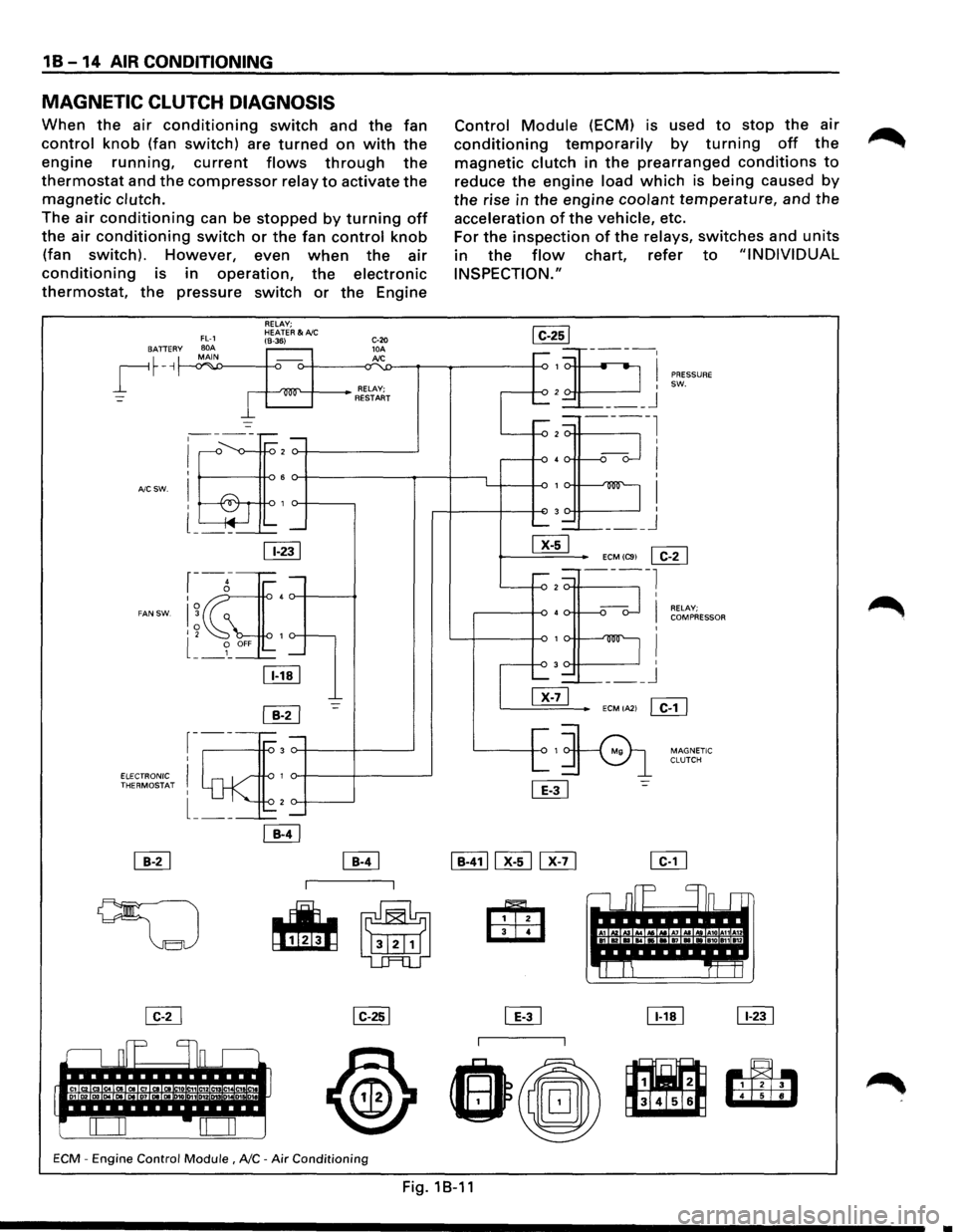
MAGNETIC CLUTCH DIAGNOSIS
When the air conditioning switch and the fan
control knob (fan switch) are turned on with the
engine running, current flows through the
thermostat and the compressor relay to activate the
magnetic clutch.
The air conditioning can be stopped by turning off
the air conditioning switch or the fan control knob
(fan switch). However, even when the air
conditioning is in operation, the electronic
thermostat, the pressure switch or the Engine
BATTER y
~
A/C SW.
FAN SW.
FL-1 BOA MAIN -.Y""'
I
RELAY; HEATER&A/C (8-36)
-
·~
~-----;::: -
I ,--<> -v--ro 2
I 6
! -&r ro 1 l ~ .... --~-'---
11-231
r-g-I 4
I~ 0 I 2 1
l __ 9_ OFF -
lli!J
~
r-----3 I
I 1
I 2 -
ELECTRONIC ~ THERMOSTAT
l __ _
C-20 10A Jd.C
RELAY; RESTART
-=-
ECM -Engine Control Module , NC -Air Conditioning
Control Module (ECM) is used to stop the air
conditioning temporarily by turning off the
magnetic clutch in the prearranged conditions to
reduce the engine load which is being caused by
the rise in the engine coolant temperature, and the
acceleration of the vehicle, etc.
For
the inspection of the relays, switches and units
in the flow chart, refer to "INDIVIDUAL
INSPECTION."
,....-1
2 ......_
.....-=.-2
40. r-
1v-
3
......._ =--
~
I ___ j
PRESSURE
SW.
ECMIC91
~
---2 ----l
•o--
1v-
3
-~-@]
~1
L
[ill
I
I RELAY; COMPRESSOR
I
I I ___ j
ECMIA21 ~
:=:>
MAGNETIC
CLUTCH
,.----I In_ r-r
A1 Kl ., .. ...... A& .. A7 AI ld A10 A11A12 .... •• ., .. a1o an 112
'It!
~
~
Fig.1B-11
Page 92 of 1928
1 D-4 COMPRESSOR OVERHAUL
6. Perform oil return operation.
7. Remove the compressor and recheck the
amount of oil.
8. Adjust the compressor oil, if necessary.
Collected Amount
more than 90cc
(3.0
fl.oz.)
Charging Amount
same as collected amount
less than 90cc (3.0 fl.oz.) 90cc (3.0 fl.oz.)
Checking and Adjusting for Compressor
Replacement
150cc (5.0 fl.oz.) of oil is charged in compressor
(service parts).
So it is necessary to drain the
proper
amount of oil from the new compressor.
1. Perform oil return operation.
2. Discharge and recover refrigerant and remove
the compressor.
3. Drain the compressor oil and measure the
extracted
oil.
4. Check the compressor oil for contamination.
5. Adjust oil level as required.
Amount of oil drained
from used compressor
less than 90cc
(3.0
fl.oz.)
Draining amount of oil
from new compressor
Same as drained
amount
more than 90cc (3.0 fl.oz.) 90cc (3.0 fl.oz.)
6. Evacuate, charge and perform oil return oper
ation.
7. Check system operation.
CONTAMINATION OF COMPRESSOR OIL
Unlike engine oil, no cleaning agent is added to the
compressor
oil. Even if the compressor runs for a
long period
of time (approximately 1 season), the
oil never becomes contaminated as long
as there is
nothing
wrong with the compressor or its method
of use.
Inspect the extracted oil for any of the following
conditions:
• The capacity of the oil has increased.
• The oil has changed color to red.
• Foreign substances, metal powder, etc., are
present in the oil.
If any of these conditions exists, compressor oil
is contaminated. Whenever contaminated com
pressor
oil is discovered, the receiver/dryer must
be
replaced.
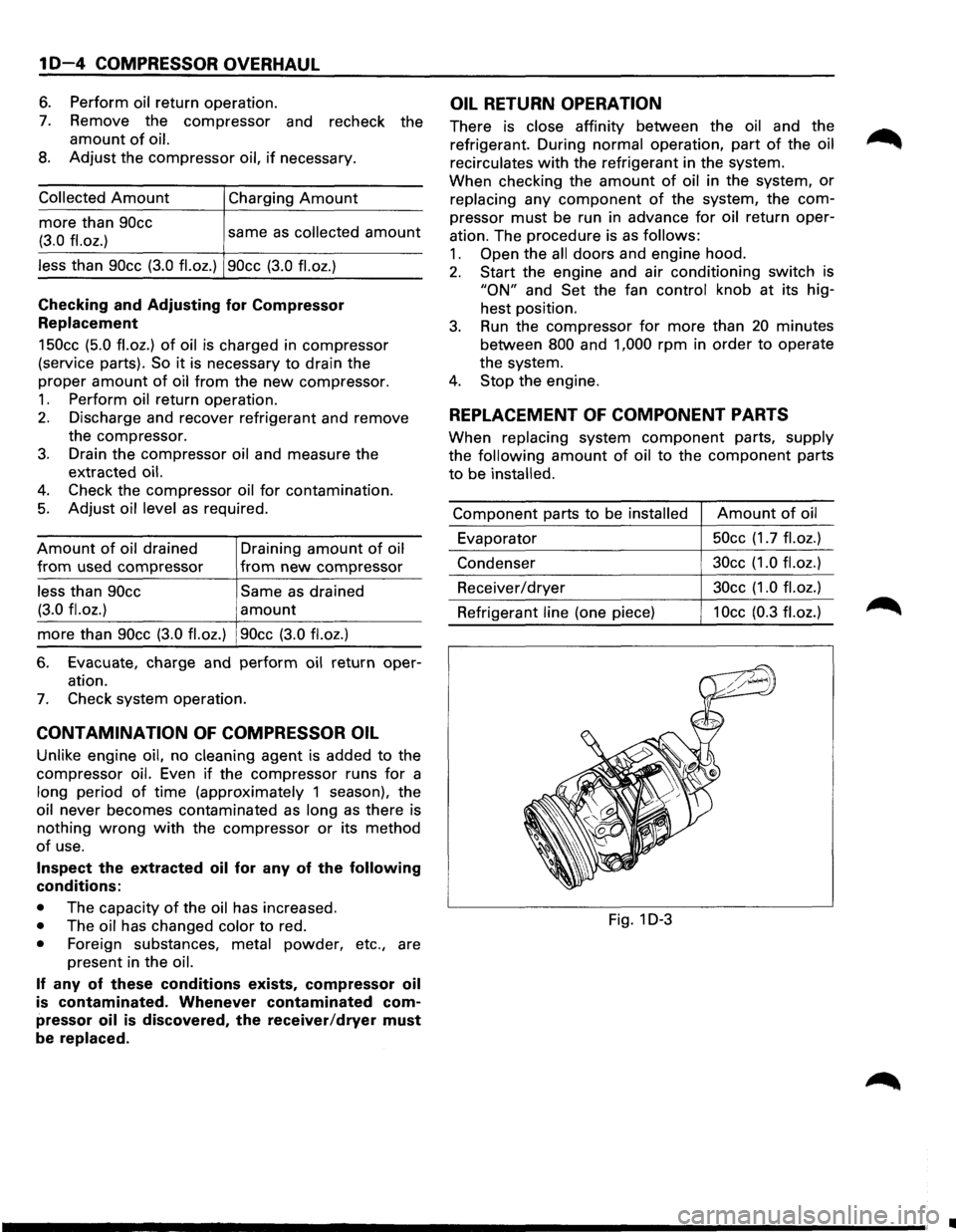
OIL RETURN OPERATION
There is close affinity between the oil and the
refrigerant. During normal operation, part
of the oil
recirculates
with the refrigerant in the system.
When checking the
amount of oil in the system, or
replacing any component of the system, the com
pressor
must be run in advance for oil return oper
ation. The procedure is as
follows:
1. Open the all doors and engine hood.
2. Start the engine and air conditioning switch is
"ON" and Set the fan control knob at its hig
hest position.
3. Run the compressor for more than 20 minutes
between
800 and 1,000 rpm in order to operate
the system.
4. Stop the engine.
REPLACEMENT OF COMPONENT PARTS
When replacing system component parts, supply
the following
amount of oil to the component parts
to be installed.
Component parts to be installed Amount of oil
Evaporator 50cc
(1.7
fl.oz.)
Condenser 30cc
(1.0 fl.oz.)
Receiver/dryer 30cc
(1.0 fl.oz.)
Refrigerant line (one piece) 1 Occ (0.3 fl. oz.)
Fig. 1 D-3
•
Page 141 of 1928
POWER STEERING SYSTEM TEST
TEST PROCEDURE
Test of fluid pressure in the power steering system is
performed to determine whether
or not the oil pump
and
power steering unit are functioning normally.
The power steering system test is method used to
identify and
isolate hydraulic circuit difficulties. Prior
to performing this test, the following inspections and
corrections,
if necessary, must be made.
[!) INSPECT
• Pump reservoir for proper fluid level.
•
Pump belt for proper tension.
• Pump driver pulley condition.
1. Place a container under the pump to catch the
fluid when disconnecting or connecting the
hoses.
2. With the engine NOT running, disconnect the
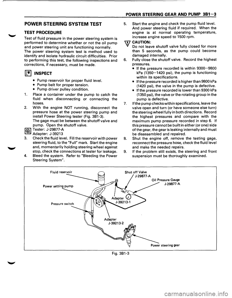
pressure hose
at the power steering pump and
install Power Steering tester (Fig. 3B1-3).
The gage
must be between the shutoff valve and
pump.
Open the shutoff valve.
li5\l Tester: J-29877-A
~ Adapter: J-39213
3. Check the fluid level. Fill the reservoir with power
steering fluid, to the "Full" mark. Start the engine
and,
momentarily holding steering wheel against
stop, check the connections at tester
for leakage.
4. Bleed the system. Refer to "Bleeding the Power
Steering
System".
POWER STEERING GEAR AND PUMP 381-3
5. Start the engine and check the pump fluid level.
And power steering fluid if required. When the
engine is at
normal operating temperature,
increase engine speed to 1500 rpm.
U7 CAUTION:
VI Do not leave shutoff valve fully closed for more
than 5 seconds,
as the pump could become
damaged
internally.
6. Fully close the shutoff valve. Record the highest
pressures.
• If the pressure recorded is within 9300-9800
kPa (1350-1420 psi), the pump is functioning
within its specifications.
• If the pressure recorded is higher than 9800 kPa
(1420 psi), the valve in the pump is defective.
• If the pressure recorded is lower than 9300 kPa
(1350 psi), the valve or the rotating group in the
pump is defective.
7. If the pump checks within specifications, leave the
valve open and turn (or have someone else turn)
the steering
wheel fully in both directions. Record
the highest pressures and compare
with the
maximum pump pressure recorded in step
6. If
this pressure cannot be built in either (or one) side
ofthe gear, the gear is leaking internally and must
be disassembled and repaired.
8. Shut the engine off, remove the testing gage,
reconnect the pressure hose, check the
fluid level
and make the needed repairs.
9. If the problem still exists, the steering and front
suspension must be thoroughly examined.
Shut off Valve
J-29877-A
Oil Pressure Gauge
J-29877-A
Fig. 3B1-3
Page 142 of 1928
381 - 4 POWER STEERING GEAR AND PUMP
ON-VEHICLE SERVICE
MAINTENANCE
The hydraulic system should be kept clean and fluid
level in the reservoir should be checked at regular
intervals
and fluid added when required. Refer to
"MAINTENANCE AND LUBRICATION" in section OB
ofthe manual for type offluid to be used and intervals
for filling.
If the system contains some dirt, flush it as detailed
later
in this section. If it is exceptionally dirty, both the
pump and the gear must be completely disassembled
before further usage.
All tubes, hoses, and fittings should be inspected for
leakage at regular intervals. Fittings must be tight.
Make sure the clips, clamps and supporting tubes and
hoses are in
place and properly secured.
Power steering hoses and lines must not be twisted,
kinked or tightly bent. Air in the system will cause
spongy action and noisy operation. When a hose is
disconnected
or when fluid is lost, for any reason, the
system must be bled after refilling. Refer to "Bleeding
the Power Steering System" in this section.
FLUID LEVEL
1. Run the engine until the power steering fluid
reaches normal operating temperature, about
55°C (130°F), then shut the engine off.
2. Check the level of fluid in the reservoir.
3. If the fluid level is low, add power steering fluid
as specified in "MAINTENANCE AND LUBRI
CATION" in Section OB to the proper level and
install the receiver cap.
4. When checking the fluid level after the steering
system has been serviced,
air must be bled from
the system. Refer to "Bleeding the Power
Steering
System" in this section.
BLEEDING THE POWER STEERING
SYSTEM
When a power steering pump or gear has been
installed, or an oil line has been disconnected, the air
that has entered the system must be bled out before
the vehicle is operated. If air is allowed to remain in
the power steering fluid system, noisy and
unsatisfactory operation of the system may result.
BLEEDING PROCEDURE
When bleeding the system, and any time fluid is
added
to the power steering system, be sure to use
only power steering fluid as specified in
"MAINTENANCE AND LUBRICATION" in section OB.
1. Fill the pump fluid reservoir to the proper level
and let the fluid settle for at least two minutes.
2. Start the engine and let it run for a few seconds.
Do
not turn the steering wheel. Then turn the
engine off.
3. Add fluid if necessary.
4. Repeat the above procedure until the fluid level
remains constant after running the engine.
5. Raise the front end of the vehicle so that the
wheels are off the ground.
6. Start the engine. Slowly turn the steering wheel
right and left, lightly contacting the wheel stops.
7. Add power steering fluid if necessary.
8. Lower the vehicle and turn the steering wheel
slowly from lock to lock.
9. Stop the engine. Check the fluid level and refill
as required.
10.
If the fluid is extremely foamy, allow the vehicle
to stand a few minutes and repeat the above
procedure.
~ INSPECT
• Belt for tightness.
• Pulley for looseness or damage. The pulley
should not wobble with the engine running.
• Hoses so they are not touching any other parts
of the vehicle.
• Fluid level
and fill to the proper level.
FLUSHING THE POWER STEERING
SYSTEM
1. Raise the front end of the vehicle off the ground
until the wheels are free to turn.
2. Remove the fluid return line at the pump inlet
connector and plug the connector port on the
pump.
Position the line toward a large container to
catch the draining fluid.
3. While running the engine at idle, fill the reservoir
with new power steering fluid. Turn the steering
wheel in both directions. DO NOT contact wheel
stops or hold the wheel in a corner, or fluid will
stop and the pump will be in pressure relief mode.
A sudden
overflow from the reservoir may
develop if the wheel is held at a stop.
4. Install all the lines and hoses. Fill the system with
new power steering fluid and bleed the system
as described in "Bleeding The Power Steering
System". Operate the engine for about 15
minutes.
Remove the
pump return line at the pump inlet
and plug the connection on the pump. While
refilling the reservoir, check the draining fluid for
contamination. If foreign material is still evident,
replace all lines, disassemble and clean or replace
the power steering system components. Do not
re-use any drained power steering fluid.
~
~
Page 219 of 1928
SUPPLEMENTAL RESTRAINT SYSTEM (SRS) STEERING WHEEL & COLUMN 3F4-9
B INSTALLATION
6. Combination switch and SRS coil assembly
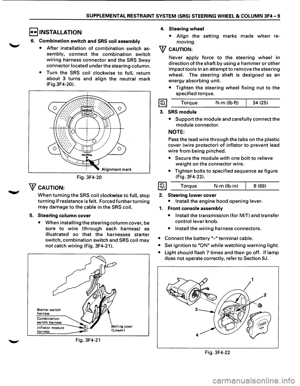
•
After installation of combination switch as
sembly, connect the combination switch
wiring harness connector and the SRS 3way
connector located under the steering column.
•
Turn the SRS coil clockwise to full, return
about 3
turns and align the neutral mark
(Fig.3F4-20).
Alignment mark
Fig. 3F4-20
WcAUTION:
When turning the SRS coil clockwise to full, stop
turning if resistance is felt. Forced further turning
may damage to the cable in the SRS coil.
5. Steering column cover
• When installing the steering column cover, be
sure
to wire (through each harness) as
illustrated so that the harnesses starter
switch,
combination switch and SRS coil may
not catch wiring (Fig. 3F4-21 ).
Starter switch
harness
Combination switch harness
Inflator module harness
Fig. 3F4-21
4. Steering wheel
• Align the setting marks made when re
moving.
W CAUTION:
Never apply force to the steering wheel in
direction
of the shaft by using a hammer or other
impact tools in an attempt to remove the steering
wheel. The steering shaft is designed as an
energy absorbing unit.
• Tighten the steering wheel fixing nut to the
specified torque.
Torque
N·m (lb-ft) 34 (25)
3. SRS module
• Support the module and carefully connect the
module connector.
NOTE:
Pass the lead wire through the tabs on the plastic
cover (wire protector) of inflator to prevent lead
wire from being pinched.
• Secure the module with one bolt to relieve
weight on the connector wire.
• Tighten bolts to specified sequence as figure
(Fig. 3F4-22).
Torque
N·m (lb·in) 8 (69)
2. Steering lower cover
• Install the engine hood opening lever.
1. Front console assembly
• Install
the transmission (for MfT) and transfer
control lever knob.
• Install the wiring harness connectors.
• Connect the battery "-"terminal cable.
• Set
ignition to ·oN" while watching warning light.
•
Light should flash 7 times and then go off. If lamp
does not operate correctly, refer to Section 9J.
Fig. 3F4-22
Page 222 of 1928
3F4 -12 SUPPLEMENTAL RESTRAINT SYSTEM (SRS) STEERING WHEEL & COLUMN
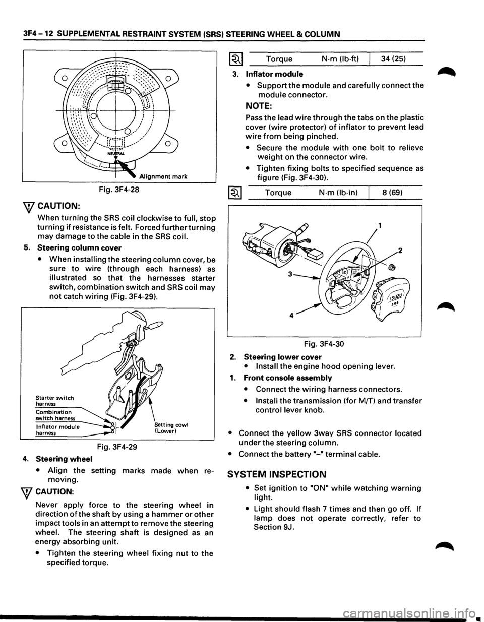
Alignment mark
Fig. 3F4-28
\fCAUTION:
When turning the SRS coil clockwise to full, stop
turning if resistance is felt. Forced further turning
may damage to the cable in the SRS coil.
5. Steering column cover
• When installing the steering column cover, be
sure
to wire (through each harness) as
illustrated so that the harnesses starter
switch,
combination switch and SRS coil may
not catch wiring (Fig. 3F4-29).
Starter switch
harness
Combination
switch harness
Inflator module
harness
4. Steering wheel
Fig. 3F4-29
• Align the setting marks made when re
moving.
\fCAUTION:
Never apply force to the steering wheel in
direction
of the shaft by using a hammer or other
impacttools in an attemptto remove the steering
wheel. The steering shaft is designed as an
energy absorbing unit.
• Tighten the steering wheel fixing nut to the
specified torque.
~~~ Torque N·m (lb-ft) 34 (25)
3. Inflator module
• Support the module and carefully connect the
module connector.
NOTE:
Pass the lead wire through the tabs on the plastic
cover (wire protector) of inflator to prevent lead
wire from being pinched.
• Secure the module with one bolt to relieve
weight on the connector wire.
• Tighten fixing bolts to specified sequence as
figure (Fig. 3F4-30).
1~1 Torque N·m (lb-in) 8 (69)
Fig.
3F4-30
2. Steering lower cover
• Install the engine hood opening lever.
1. Front console assembly
• Connect the wiring harness connectors.
• Install the transmission (for Mff) and transfer
control lever knob.
• Connect the yellow 3way SRS connector located
under the steering column.
• Connect the battery"-" terminal cable.
SYSTEM INSPECTION
• Set ignition to "ON" while watching warning
light.
•
Light should flash 7 times and then go off. If
lamp does not operate correctly, refer to
Section 9J.
Page 226 of 1928
3F4-16 SUPPLEMENTAL RESTRAINT SYSTEM (SRS) STEERING WHEEL & COLUMN
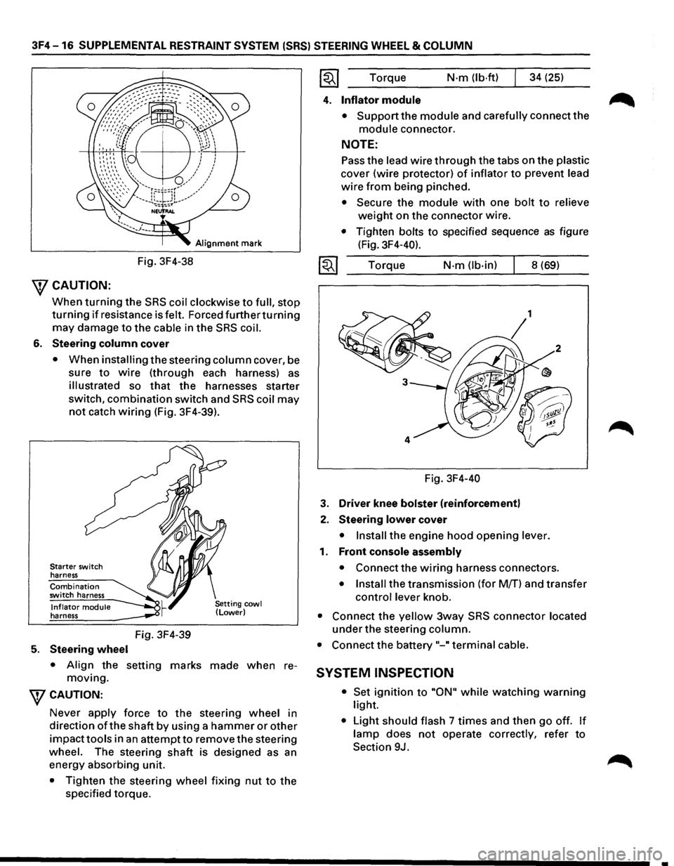
Alignment mark
Fig. 3F4-38
\fCAUTION:
When turning the SRS coil clockwise to full, stop
turning if resistance is felt. Forced furtherturning
may damage to the cable in the SRS coil.
6. Steering column cover
• When installing the steering column cover, be
sure
to wire (through each harness) as
illustrated so that the harnesses starter
switch,
combination switch and SRS coil may
not catch wiring (Fig. 3F4-39).
Starter switch
harness
Combination switch harness
Inflator module harness
5. Steering wheel
Fig. 3F4-39
• Align the setting marks made when re
moving.
WCAUTION:
Never apply force to the steering wheel in
direction
ofthe shaft by using a hammer or other
impacttools in an attempt to remove the steering
wheel. The steering
shaft is designed as an
energy absorbing unit.
• Tighten the steering wheel fixing nut to the
specified torque. Torque
N·m (lb·ftl 34
(25)
4. Inflator module
• Support the module and carefully connect the
module connector.
NOTE:
Pass the lead wire through the tabs on the plastic
cover (wire protector) of inflator to prevent lead
wire from being pinched.
• Secure the module with one bolt to relieve
weight on the connector wire.
• Tighten bolts to specified sequence as figure
(Fig. 3F4-40).
Torque
N·m (lb-in) 8 (69)
Fig. 3F4-40
3. Driver knee bolster (reinforcement)
2. Steering lower cover
• Install the engine hood opening lever.
1. Front console assembly
• Connect the wiring harness connectors.
• Install the transmission (for M/T) and transfer
control lever knob.
• Connect the yellow 3way SRS connector located
under the steering column.
• Connect the battery "-"terminal cable.
SYSTEM INSPECTION
• Set ignition to "ON" while watching warning
light.
• Light should flash 7 times and then go off. If
lamp does not operate correctly, refer to
Section 9J.
•
Page 281 of 1928
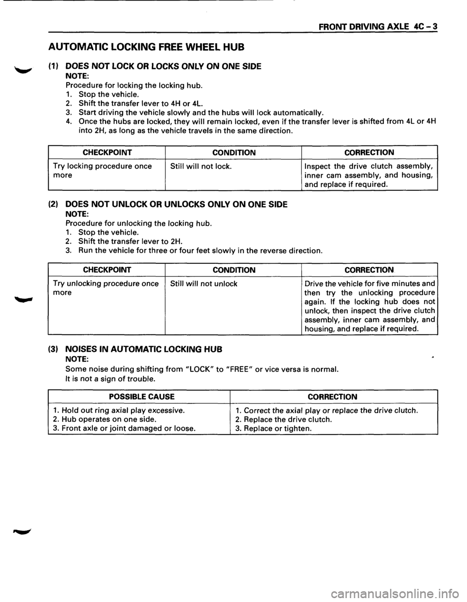
AUTOMATIC LOCKING FREE WHEEL HUB
(1) DOES NOT LOCK OR LOCKS ONLY ON ONE SIDE
NOTE:
Procedure for locking the locking hub.
1. Stop the vehicle.
2. Shift the transfer lever to 4H or 4L.
FRONT DRIVING AXLE 4C-3
3. Start driving the vehicle slowly and the hubs will lock automatically.
4. Once the hubs are locked, they will remain locked, even if the transfer lever is shifted from 4L or 4H
into 2H, as long as the vehicle travels in the same direction.
CHECKPOINT
CONDITION
Try locking procedure once Still will not lock.
more
(2) DOES NOT UNLOCK OR UNLOCKS ONLY ON ONE SIDE
NOTE:
Procedure for unlocking the locking hub.
1. Stop the vehicle.
2. Shift the transfer lever to 2H.
CORRECTION
Inspect the drive clutch assembly,
inner cam assembly, and housing,
and replace
if required.
3. Run the vehicle for three or four feet slowly in the reverse direction.
CHECKPOINT
CONDITION CORRECTION
Try unlocking procedure once Still will not unlock Drive the vehicle for five minutes and
more
(3) NOISES IN AUTOMATIC LOCKING HUB
NOTE:
then try the unlocking procedure
again.
If the locking hub does not
unlock, then inspect the drive clutch
assembly,
inner cam assembly, and
housing, and replace
if required.
Some noise during shifting from "LOCK" to "FREE" or vice versa is normal.
It
is not a sign of trouble.
POSSIBLE CAUSE CORRECTION
1. Hold out ring axial play excessive. 1. Correct the axial play or replace the drive clutch.
2. Hub operates on one side. 2. Replace the drive clutch.
3. Front axle or joint damaged or loose. 3. Replace or tighten.
Page 322 of 1928
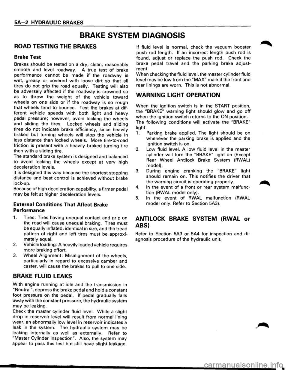
SA-2 HYDRAULIC BRAKES
BRAKE SYSTEM DIAGNOSIS
ROAD TESTING THE BRAKES
Brake Test
Brakes should be tested on a dry, clean, reasonably
smooth and
level roadway. A true test of brake
performance cannot be made
if the roadway is
wet, greasy
or covered with loose dirt so that all
tires do not grip the road equally. Testing will also
be adversely affected if the roadway is crowned so
as to throw the weight of the vehicle toward
wheels on one side or if the roadway is so rough
that wheels tend to bounce. Test the brakes at dif
ferent vehicle speeds with both light and heavy
pedal pressure; however, avoid locking the wheels
and sliding the tires. Locked wheels and sliding
tires do not indicate brake efficiency, since heavily
braked but turning wheels will stop the vehicle in
less distance than locked wheels. More tire-to-road
friction is present
with a heavily braked turning tire
then
with a sliding tire.
The standard brake system is designed and
balanced
to avoid locking the wheels except at very high
deceleration
levels.
It
is designed this way because the shortest stopping
distance and best
control is achieved without brake
lock-up.
Because of high deceleration capability, a firmer pedal
may be felt at higher deceleration levels.
External Conditions That Affect Brake
Performance
1.
2.
3.
Tires: Tires having unequal contact and grip on
the road
will cause unequal braking. Tires must
be equally inflated, identical in size, and the tread
pattern
of right and left tires must be approxi
mately equal.
Vehicle loading:
A heavily loaded vehicle requires
more braking effort.
Wheel Alignment: Misalignment of the wheels,
particularly
in regard to excessive camber and
caster,
will cause the brakes to pull to one side.
BRAKE FLUID LEAKS
With engine running at idle and the transmission in
"Neutral", depress the brake pedal and hold a constant
foot pressure on the pedal. If pedal gradually falls
away with the constant pressure, the hydraulic system
may be leaking.
Check the master cylinder fluid level. While a slight
drop in reservoir level will result from normal lining
wear, an abnormally low level in reservoir indicates a
leak in the system. The hydraulic system may be
leaking internally as well as externally. Refer to
"Master Cylinder Inspection". Also, the system may
appear
to pass this test but still have slight leakage. If
fluid level
is normal, check the vacuum booster
push rod
length. If an incorrect length push rod is
found, adjust
or replace the push rod. Check the
brake
pedal travel and the parking brake adjust
ment.
When checking the
fluid level, the master cylinder fluid
level
may be low from the "MAX" mark if the front and
rear
linings are worn. This is not abnormal.
WARNING LIGHT OPERATION
When the ignition switch is in the START position,
the
"BRAKE" warning light should glow and go off
when the ignition switch returns to the ON position.
The
following conditions will activate the "BRAKE"
light:
1. Parking brake applied. The light should be on
whenever the parking brake is applied and the
ignition switch is on.
2. Low fluid level. A low fluid level in the master
cylinder will turn the "BRAKE" light on (Except
Rear
Wheel Antilock Brake System (RWAL)
model).
3. During engine cranking the "BRAKE" light
should
remain on. This notifies the driver that
the warning circuit is operating properly.
4. In the event of a front or rear system malfunc
tion (RWAL model only).
5. In the event of RWAL malfunction (RWAL
model only. Refer to Section 5A3).
ANTILOCK BRAKE SYSTEM (RWAL or
ABS}
Refer to Section 5A3 or 5A4 for inspection and di
agnosis procedure of the hydraulic unit.
..